
INTERACTIVE WHITEBOARD FOR COLLABORATIVE WORK
A Multi-agent based Solution
Franck Gechter and St
´
ephane Galland
ICAP Team, Laboratoire Syst
`
emes et Transports (SeT)
Universit
´
e de Technologie de Belfort-Montb
´
eliard (UTBM), Belfort, France
Keywords:
Interactive white board, Software engineering, Multi-agent system, Collaborative Work.
Abstract:
An Interactive Whiteboard (IWB) is a device that is a giant tactile and projection screen. It can be considered
as one of the main elements for pedagogical innovation with information technology. IWB allows to transform
the classical classroom environment into a working and learning interactive environment. This pedagogical
tool is particularly pertinent in higher school especially in scientific teaching where it allows to better illustrate
scientific approach thanks to the ability to record annotations in association with a time line. If the use of
IWB seems to be natural in lecture, it can also be used in tutorial and practical class where collaborative
work is particularly important. The collaborative ability is closely tied to the softwares used. Few software
have functionalities aimed at facilitate collaborative work. This feature is the main issue of this article. To
develop this ability, a multi-agent approach has been chosen. Multi-agent systems approach is one of the
most interesting thanks to its intrinsic properties and features such as simplicity, flexibility, reliability, self-
organization/emergent phenomena, low cost agent design and adaptation skills,... This paper presents the
solution developed in order to make IWB able to communicate with each other.
1 INTRODUCTION
An Interactive Whiteboard (IWB) is a device that is
both a giant tactile screen and a projection screen. It
can be considered as one of the main elements for
pedagogical innovation with information technology
by many countries. Interactive whiteboards allow to
transform the classical classroom environment into a
working and learning interactive environment that fits
edutainment aims. To that way, IWB must work in
association with a standard computer or laptop and a
data projector. One single touch allows to modify a
document, to launch applications, to open web sites,
to write annotations in electronic ink on plans, etc.
Then, modifications and pedagogical progression can
be saved and replay as many time it is required. This
feature is one of the principal key points of IWB as
compared with classical blackboard.
Nowadays, IWB are mainly used in primary and sec-
ondary schools. For instance, in Great Britain nearly
100 percent of primary schools are equipped by a
IWB. By the same, in France, IWB equipment is sup-
ported by a national action called PrimTICE
1
. As for
1
http://primtice.education.fr
higher education, the use of IWB depends on schools
and universities policies. For the moment, especially
in France the equipment rate is very low. However,
this pedagogical tool is particularly pertinent and al-
lows to better illustrate and emphasize scientific ap-
proach thanks to the ability to record annotations in
association with a time line. If, the use of IWB seems
to be natural in lecture, it can also be used in tuto-
rial and practical class where the collaborative work
is particularly important. The collaborative ability is
closely tied to the softwares used. The main interest
of this feature is the possibility to save and annotate
every intervention while preserving the logic behind
the solving process of the course. This record allows
each student to individually analyze the course when
back at home.
IWBs propose a wide range of pedagogical perti-
nent properties. Thus, they seem to be a good way
of promoting the use of information technology in
classrooms and of developing new pedagogical ap-
proaches. Thanks to its multimedia abilities, IWB
must put in emphasize (distant) collaborative work.
By contrast, IWBs suffer from several drawbacks.
First, the cost of such a device is important espe-
cially for heavy IWB with huge tactile screen based
270
Gechter F. and Galland S..
INTERACTIVE WHITEBOARD FOR COLLABORATIVE WORK - A Multi-agent based Solution.
DOI: 10.5220/0003340402700278
In Proceedings of the 3rd International Conference on Computer Supported Education (CSEDU-2011), pages 270-278
ISBN: 978-989-8425-49-2
Copyright
c
2011 SCITEPRESS (Science and Technology Publications, Lda.)

on resistive or capacitive technologiesn which retail
at around $10,000. This implies a sharing of the de-
vices between professors with specifically equipped
rooms, reservation, etc. Some lightweight devices can
be cheaper (i.e. around ”hundreds of dollars”). These
are generally based on optical technologies such as
Microsoft Touch Wall
2
. At the extreme low cost level,
game joypad
3
based solutions can be used but they
suffer from an artisanal approach. Second, few IWB
softwares are available on alternative operating sys-
tems such as Apple MAC OS X and Linux/Unix dis-
tributions. Finally, IWB are exclusively used in di-
rect teaching (i.e. with students in the same classroom
as the teacher). There are few functionality aimed at
facilitate distant teaching and/or collaborative work.
This last feature is the one we choose to deal with in
this paper. To that end, a reactive multi-agent system
has been developed.
Multi-agent systems are an efficient approach for
problem solving and decision making applied to a
wide range of applications. Among the classical mod-
els, the reactive approach is one of the most inter-
esting thanks to their intrinsic properties and fea-
tures such as simplicity, flexibility, reliability, self-
organization/emergent phenomena, low cost agent de-
sign and adaptation skills, etc. Such systems rely on
reactive agents, which are simple entities that behave
based on their perceptions (Ferber, 1999). Accord-
ing to (Muller, 2004), the difference between a multi-
agent system (MAS) and a classical problem-solving
method, lies in the role and in the significance of the
interactions that prevail on the definition of the agents
themselves. Moreover, agents environment also plays
a preponderant role as shown in (Weyns et al., 2005)
and (Simonin and Gechter, 2006), since it is the main
place where the system computes, builds and com-
municates. Indeed, in the reactive MAS framework,
one single agent can neither handle a representation of
the problem nor compute the global solution. Instead,
this solution is obtained from numerous agent-agent
and/or agent-environment interactions.
It has been shown that Reactive Multi-Agent
System (RMAS) approach is efficient for tack-
ling complex problems such as life-systems sim-
ulation (Parunak, 1997), cooperation of situated
agents/robots (Drogoul and Ferber, 1993) and
problem/game-solving (Drogoul and Dubreuil, 1993).
As for the behavioral models, two main trends are
generally used. The first is biologically-inspired ap-
proach such as (DiMarzo-Serugendo et al., 2004),
(Bourjot et al., 2002) or (Brueckner, 2000). The sec-
2
http://www.officelabs.com/projects/touchwall/
Pages/default.aspx
3
http://johnnylee.net/projects/wii/
ond is the use of physics-inspired behavioral models
as in (Gechter et al., 2006)), (Reynolds, 1987), or
(Zeghal and Ferber, 1994).
The goal of this paper is to present a reactive agent
solution to the collaborative work issue using Interac-
tive Whiteboard. After a general overview of IWB
principles, a presentation of the IWB software devel-
oped in the UTBM
4
is made. Then, next section fo-
cuses on collaborative work feature, describing in de-
tail the reactive multi-agent system designed. Finally,
the paper concludes with a description of future work.
2 INTERACTIVE WHITEBOARD
PRINCIPLES
2.1 Principles
An interactive Whiteboard is generally associated
with a computer, a data-projector and a projection
screen. Depending on the solution used, one can use
classical whiteboard pens (standard use) and/or elec-
tronic pens in order to write with electronic ink. IWB
allows to make anything possible with a computer and
more. IWB principle is very simple: (cf. figure 1):
Figure 1: Classical IWB principles.
1. Commands performed on the surface of the pro-
jection screen, are sent from the IWB to the com-
puter. This link can be made thanks to wifi, infra-
red or bluetooth, or with a wired solution (USB,
serial, etc.).
2. Computer build the new image to be projected
taking into account actions performed. This im-
age is then sent to the data projector with a wired
connection (VGA cable, HDMI, cable, etc.)
3. The new computed image is sent by the data-
projector on the screen. User can then interact
with the new image returning on point 1. Some
devices are also based on retro-projection or on
4
Universit
´
e de Technologie de Belfort-Montb
´
eliard -
http://www.utbm.fr
INTERACTIVE WHITEBOARD FOR COLLABORATIVE WORK - A Multi-agent based Solution
271

LCD/Plasma screen. This avoids hot spot
5
and
shadow problems.
Distant and/or collaborative work feature is close
to the option available in the software used. This fea-
ture associated to visio-conference tools will bring the
possibility to make distant lessons more attractive, dy-
namic and interactive. Distant collaborative IWB fol-
lows the same principles as the standard IWB with
small adaptations (cf. figure 2):
Figure 2: IWB for collaborative work principles.
1. Master IWB sends user’s commands to its associ-
ated computer.
2. The master computer build the new image to be
projected taking into account actions performed.
This image is then sent to the data projector with
a wired connection (VGA cable, HDMI, cable,
etc.).
3. The new computed image is sent by the data-
projector on the screen. User can then interact
with the new image retuning on point 1.
4. The image computed in point 2 mixed up with the
speaker image is sent through the network to an-
other IWB’s computer.
5
Hot spot occurs when the projection screen is not dif-
fusing enough. In this case, the lamp of the data projector
is highly reflected on one specific position on the screen(i.e.
on the intersection between screen plan and data projector
optical axis). This is generally hardly supported by the lec-
turer bringing some eye tiredness.
5. Distant computer sends the image to its associated
data-projector.
6. Data-projector sends the image to the screen.
This structure is the most widespread. However,
we can also imagine that the distant device is also an
IWB. In this case, students or another colleague can
interact and modify what is sent by the master. In the
case of several interacting devices, the master/slave
relation is no longer useful. In the network, each IWB
has to have the same priority and the same role as
other. If one device decides to quit the network, it
must be able to do this without any influence on other
IWB. This propriety has been taken into account as a
priority in the design of the presented proposal.
2.2 User’s Modes
IWB exhibits several user’s mode depending on the
type and the nature of the lesson. Here are the main
employed modes:
• classical presentation,
• whiteboard/blackboard,
• interactive presentation,
• augmented presentation, and
• distant presentation.
2.2.1 Classical Presentation
The classical presentation mode is the minimum re-
quirement for a IWB software. On the software point
of view, it is easy to develop and to put into practice
except for the use of copyrighted format for save/load
functions. Generally, it relies on a simple substitution
of the mouse movement by the specific device (infra-
red pen, fingers, etc.) adapted to IWB used. In this
situation, multi-points detection is not necessary.
2.2.2 Blackboard/Whiteboard
This mode can be considered has the minimum fea-
ture for a IWB. In this situation, the user writes as
he does with a standard teaching board but the regu-
lar ink is replaced by a virtual one projected by the
data projector. Besides the classical features with
whiteboard, IWB brings some new interesting ones
such as : saving documents and pedagogical progres-
sions, recognizing hand written script and scheme,
building immediate course documents, etc. As for
the programing/software engineering points of view,
this mode is a little bit harder to develop. The user
interface needs to be structured as a series of trans-
parent layers. Consequently, this mode is really near
CSEDU 2011 - 3rd International Conference on Computer Supported Education
272
the user’s interface encountered with image process-
ing softwares.
2.2.3 Interactive Presentation
This mode corresponds to the classical presentation
mode with a possible interaction with objects and
components such as rotation, zoom, movie control,
etc. In this mode, the multitouch ability can be really
useful. Besides classical mode, one needs to be able
to design and to include to presentation interactive
components. Good examples of reference function-
alities of interactive presentation mode can be seen
through MIT (Sketch-Interpreting Software) and Mi-
crosoft (Touchwall project) shows.
2.2.4 Augmented Presentation
Augmented presentation is a mix between classical
and/or interactive presentation mode on one side and
whiteboard mode on the other. As compared to clas-
sical presentation, annotations and modification of
components are allowed. Everything can be save in
one single format file. In this case, it is interesting
to be able to load classical presentation file (such as
.ppt or .pdf) as background layer and add on above
transparent layers interactive components.
2.2.5 Distant Presentation and Collaborative
Work
This mode relies on the synchronization of two or
more IWB. The functionalities are the same as a stan-
dard chat software with the possibilities to work si-
multaneously on the same document. This mode is
perfect for distant working meeting or distant teach-
ing since classical intervention interactivity is pre-
served.
3 INTERACTIVE WHITEBOARD
APPLICATION
This section describes the overall architecture of the
IWB application. Several modules are explained and
the networking support is specifically detailled in sec-
tion 4.
3.1 General Architecture
IWB Application is designed according to the Model-
View-Controller (MVC) architecture (Reenskaug,
2003), which is currently considered to be a major ar-
chitectural pattern used in software engineering. The
pattern isolates “domain logic” (the application logic
for the user) from the user interface (input and presen-
tation), permitting independent development, testing
and maintenance of each (separation of concerns).
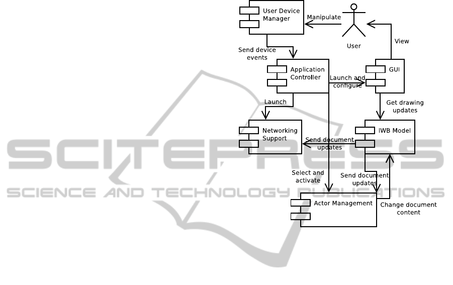
Figure 3: Component Diagram of the IWB Application.
Figure 3 illustrates the software components of
the IWB application. Application controller is the
core component. Its roles are to launch the other
components of the application and to control the data
and control flows between the components. Logic of
the IWB application is embedded in the IWB Model,
which is detailled in Section 3.2. Basically, this com-
ponent provides documents, layers and interactive ob-
jects of the application. GUI module listen to changes
in the IWB Model and give a graphical feedback to
the User (see Section 3.4). User is able to inter-
actively control the IWB application through physi-
cal devices (see Section 3.4). Corresponding device
events are translated into IWB events and forwarded
to the GUI and Actor Management components. This
last components is composed of a set of runnable
functions named actors. Actors should update the
IWB model according to their goals and constraints
(see Section 3.3). Finally to complete the overall ar-
chitecture, Networking support is providing through
an agent-based approach. This module is detailled in
Section 4.
3.2 IWB Model
IWB model includes the “domain logic” of the IWB
application. A generic logic model is provided by the
INTERACTIVE WHITEBOARD FOR COLLABORATIVE WORK - A Multi-agent based Solution
273
IWB model, and it should be extended and specialized
for domain-dependent applications (UML modelling,
physic simulation, etc.). This core model is based on
the concepts of document, layer and interactive com-
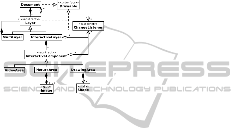
ponent. Figure 4 illustrates the UML class diagram of
this core model.
Figure 4: Class Diagram of the IWB Document Model.
More formally Equation 1 defines the core model
as the composition of a document D, a set of layers
P (L), a set of interactive components P (C), and three
functions h
1
, h
2
, and h
3
.
M ::= D × P (L) × P (C) × h
1
× h
2
× h
3
D ::= id
L ::= id
C ::= id × r
h
1
: L D
h
2
: L → L
h
3
: C L
(1)
Document and layers are defined by their identi-
fier id. Each interactive component has an identifier
id and an associated resource r (video, picture, col-
lection of shapes, etc.). Class diagram in Figure 4
contains hierarchical relations between the document,
layers and interactive components. This relationship
is formally defined by the surjective function h
1
, the
function h
2
, and the injective function h
3
. They map
an object o to the object which is containing o. h
1
,
h
2
, and h
3
denote respectively the layer-to-document,
layer-to-layer, and component-to-layer relationships.
IWB Model is designed to be independent from
any user interface library. In this way, it implements
several design patterns (Coplien and Schmidt, 1995):
• Composite: layers are composed of layers, which
are composed of layers in turn, etc.
• Bridge: IWB model is exhibiting a set of inter-
faces for high-level features and abstract roles:
Drawable, Actionable, Movable, Selectable, etc.
• Facade: IWBEnvironment is representing all the
IWB data model. It permits to manage actors, up-
date the data model, or retreive interactive actions.
• Observer: All the changes in the IWB data model
are sent to event listeners, which want to be noti-
fied on.
• Strategy: IWB data logic and interaction manipu-
lation logic are respectively embedded in the Doc-
ument and InteractiveActor classes.
3.3 Actor Management
Actor is a runnable function which is updating the
IWB model according to external events and their in-
ternal states. Each actor should define a a function
according to Equation 2.
a : S × M × P (E) → S × M (2)
Function a takes three parameters: (i) the internal
state of the actor S, (ii) the state of the IWB model M,
and (iii) a powerset of all the possible events E, which
may occur in the application. Function a updates the
internal state of the actor in one hand; and it replies a
new state for the IWB model in the other.
Internal state of an actor depends on its goal. Ac-
tors are basically defined by statecharts in which tran-
sitions are traversable according to device events such
as mouse button release or mouse motion. When a
statechart’s state of the actor is reached, an action on
the GUI or on the IWB model is run. Let take the
“Mover” actor. Its goal is to move an interactive com-
ponent when the user clicked on it and then moved it
(see Figure 5).
Actor management is modular and independent
from the implementation from the other IWB appli-
cation modules, except for IWB model. Create new
actors for IWB application is simple and fast to tackle.
For example, animation of graphical components ac-
cording to simulation rules is done by a dedicated ac-
tor which takes only time progression events as pa-
rameters.
Figure 5 illustrates two standard actors in the IWB
architecture: the selector and the mover.
Selector actor is an interactive process which is
permitting to put an interactive component in a list of
selected objects. This actor reacts when the user has
pressed a mouse button. Mover actor has the role to
move an interactive component at an other location
on the IWB screen. It reacts when the user is pressing
a mouse button and retreive the component under the
CSEDU 2011 - 3rd International Conference on Computer Supported Education
274
class Selector extends InteractiveActor {
void mousePressed(MouseEvent e) {
InteractiveComponent c = getComponentAt(e.getPoint());
getSelectionManager().select(c);
}
}
class Mover extends InteractiveActor {
Vector v;
InteractiveComponent catched;
void mousePressed(MouseEvent e) {
catched = getComponentAt(e.getPoint());
if (catched!=null) {
v.sub( catched.getPosition(), e.getPoint());
}
}
void mouseRelease(MouseEvent e) {
if (catched!=null) {
p.add( e.getPoint(), v );
catched.setPosition( p );
catched = null;
}
}
}
Figure 5: Example of Implementation of Selector and
Mover actors — using Java-like Syntax.
mouse location. Then, when the user is releasing the
mouse button, the actor is moving the component at
the new position.
3.4 User Interface and Advanced
Interaction Devices
User interface module provides a graphical feedback
to the User. As illustrated by Figure 4, elements of
the IWB model fire events when their content or their
properties have changed. GUI is listening these events
and update the graphical context. But even if this ap-
proach is very closed to MVC principles, it is not
directly applicable to many rendering engine (Java
Swing and Java 3D for example). Indeed these en-
gines run an infinite loop on the screen rendering.
Each time this loop is run, all the graphical screen
must be drawn. To improve graphical performances
of the IWB applications, GUI is not listening on IWB
model events but invoke painting functions of Draw-
bable objects, and all the IWB model elements are
Drawable (see Figure 4).
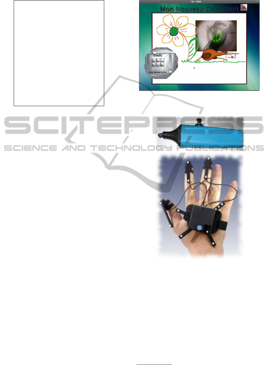
Design principles of the user interface permits to
use any graphic interface library. For example, Fig-
ure 6 illustrates the use of Java3D to render the com-
ponents inside a 3D virtual whiteboard. Only the
menus and the toolbars must be implemented on this
3D library. The IWB model is simply a 2D picture put
on a 3D plane. Of course, the choice of the graphical
library is also related to its ability to provide a support
for advanced devices.
In addition to the standard keyboard and mouse, it
is possible to use advanced devices to interact with
the IWB application. These advanced devices are
mainly used in lecture context: Wiimote
R
, LED pen,
Figure 6: IWB Application Screenshot with Java3D User
Interface.
Figure 7: LED Pen and Dtrack
R
Devices.
Dtrack
R
, etc.
Wiimote
R
uses of infrared light to locate the po-
sition of the device in space. LED pen, illustrated
by Figure 7, is used with a webcam at the top of the
screen to locate the position of the user. Dtrack
R
6
is virtual reality tracking system successfully used by
the IWB application.
tr
d
: D → P (E) (3)
All the device drivers are defined by a function tr
d
in Equation 3. Function tr
d
takes as parameter the
state of the physical device. This state depends on the
6
http://www.ar-tracking.com
INTERACTIVE WHITEBOARD FOR COLLABORATIVE WORK - A Multi-agent based Solution
275

type of device but should contains at least a position
(on the plane or in the space), and several indicators
about the button’s states. Function tr
d
transforms the
device’s state d into a set of events P (E), which are
comprehensible by the IWB actors. These events are
directly forwarded to the actor under execution. In
case of 3D devices, Function tr
d
should project the
3D position on the plane of the IWB screen.
4 USING REACTIVE AGENTS TO
MAKE WHITEBOARDS
COLLABORATE
4.1 Problem Overview
The common idea that first come out when it is de-
cided to make several processes collaborate through
a network is the use of a classical client/server ar-
chitecture. In this education paradigm, one server,
somewhere on the network, plays teacher’s role.
Clients connected to this server play student’s role.
Server/Teacher brings new document on the board,
share them, draw comments. If they want to mod-
ify the whiteboard, clients/students must ask to the
server/teacher to take the control of the board. This
architecture works like the reality in teaching room,
but with more flexibility and modularity thanks to the
use of information technology concepts. Another ap-
proach is the classical blackboard collaborative struc-
ture. Most of the classical collaborative proposals
found in literature are based on one of these meth-
ods (Tewissen et al., 2000; Komis et al., 2002; Aiken
et al., 2005). By contrast to this, we decided to
design a totally different architecture for collabora-
tive work. This is based on a decentralized solution
that stems from classical multi-agent system applica-
tions. In this case, each IWB is considered to be an
agent able to modify the work of any other linked en-
tity. There is no longer a leader/server and follow-
ers/clients, since every whiteboard play the same role
on the network. Each agent has a copy of the collec-
tive work. This copy is updated thanks to its personal
modifications and to other connected IWB modifica-
tions. Indeed, each time one IWB changes something
locally, modifications, i.e. events, are transmitted to
its nearest neighbors
7
, and then from one agent to the
other all the connected IWB received the modifica-
tions. Besides, this architecture allows agent to con-
nect/disconnect the IWB network in run time with-
out involving perturbations in the system. When, one
7
This notion will be detail in the next paragraph.
connects to the IWB network, it receives all the past
modifications and update its own copy of the board.
When this agent disconnects, it keeps its own copy
that can be locally saved and stop all interaction with
other IWB agents.
4.2 Agents’ Behaviors
Previous section presents a global overview of the
problem. This paper will now focus on the details of
this proposal. As already said, let now consider one
IWB to be an agent. Each agent has its own board on
which it is working. When connected, the behaviors
of this agent are the following:
• Manage the list of nearest neighbors.
• Transmit each modification (i.e. action on interac-
tive component) of its own board copy to its near-
est neighbors.
• When one remote modification is received from
one of its neighbor, update its own copy if neces-
sary.
In addition to these behaviors, we can also add two
transitional behaviors aimed at connecting the agent
to the IWB network and quitting it. All these behavior
are summarized in figure 8. We will now detail them.
Board local copy update
M
o
d
i
f
i
c
a
t
i
o
n
e
v
e
n
t
Neighborhood update
Figure 8: IWB Agent behaviors.
CSEDU 2011 - 3rd International Conference on Computer Supported Education
276

4.2.1 Connecting the Network
First of all, each IWB must be configured to be
able to share information. The first IWB starts its
server thread which is waiting for external connec-
tion. When a new IWB is coming, it has to know
one IP address of one member of the IWB network.
When only one IWB is already on the network its ad-
dress must be known, but when there are more than
one IWB, any IP address is sufficient. When con-
nected, the newcomer receives all the modification
event required to obtain the same working document
as any other IWB on the network. This includes the
background, interactive components state, relations
between components, etc. Not all the information
since the beginning of the network are sent. Indeed,
only the last informative modification are memorized.
For instance, when one component is moved once and
then moved again at another place, only the last place
is memorized and then sent to newcomers. From now
on, the connected IWB is able to collaborate.
4.2.2 Neighborhood Management
When connected, each IWB agent starts to search for
its nearest neighbors. For this, after a successful con-
nection to the agents network, the newcomer ask the
neighbor list of its access point (i.e. the agent, the IP
of which has served to the connection). One neigh-
bor is considered to be near one IWB when its time
response is lower than others’. Thus, each agent will
build incrementally a list of their nearest neighbors.
This list is managed by a thread that updates neigh-
borhood taking into account the time stamp of each
received modification event. Using this strategy, each
IWB is able to maintain up to date a list of the more
efficient neighbors. This list changes in run time de-
pending on the arrival/departure of IWB and on phys-
ical network traffic. In some cases, one agent can de-
cide to remove one of its neighbor, especially because
this has a response time below all other agents in the
neighborhood. It this case, a message is sent to the
slower agent to retrieve its acknowledge. If this is
positive, the agent is removed from the list, if nega-
tive it is kept. This is required to maintain links to
every agent, especially when one of them is isolated.
If the only link an agent had with the network is cut
without asking, we risk to loose some agents in run
time.
4.2.3 Modification Transmission
Each time one IWB agent modify one interactive
component, one event is generated. This event is
composed by a series of values which corresponds to
the modification performed on the considered compo-
nent. Three different types of main remove event has
been defined:
• New Layer Event : Creation of a new layer in the
document.
• New Component Event: Creation of a new interac-
tive component such as hand writing area, picture,
etc.
• Component Modification Event: Modification of
the shape, size, position, etc. of one specific com-
ponent.
Moreover, each event includes also a time stamp cor-
responding on the time/date of the modification. If
the modification is the creation of a new component
a special new component event is generated includ-
ing all the necessary characteristics. For instance, if
this new component is a picture, the picture and its
characteristics (size, position, color depth, etc.) are
integrated in a new component event. Each picture,
independent to it initial file format is transformed into
jpeg image when loaded on one IWB. Then each so
build event is propagated, after serialization, to the
agent neighbors. This transmission is made through
classical TCP/IP sockets in order to ensure that all
messages are received.
4.2.4 Updating with Remove Modifications
When one event is received, each agent rebuild the
component and/or the list of the modifications per-
formed by deserialization. Then, each modifica-
tion/creation is performed on the local copy of the
shared board. In parallel, the received event is also
propagated to the receiver agent neighbors in order to
ensure that all connected IWB received each event.
If one event has already been received, it is directly
trashed without propagation to neighbors. Indeed,
there is no need to build a safety mechanism in the
IWB network protocol since the data transmission is
performed by the TCP protocol. We only have to en-
sure that each agent is able to receive each message
wherever they are connected to the IWB network.
4.2.5 Quitting the Network
When one agent decides to quit the network, it sends
to its neighbors a specific message which includes the
list of all of its neighbors. Then, when this message
is received, each receiver updates its neighbors list
by removing the quitting agent and considering new
neighbors to fill the gap remained.
INTERACTIVE WHITEBOARD FOR COLLABORATIVE WORK - A Multi-agent based Solution
277

5 CONCLUSIONS
The Interactive whiteboard software exposed in this
paper is currently passing tests in real classroom
teaching conditions. It works on most existing com-
puter platform such as Linux-PC, Windows-PC, Mac-
OSX computer. It has also already been tested in
collaborative research meeting with distant collabo-
rators. The multi-agent system developed seems to be
robust and to be able to manage several IWB without
perturbation. We now wait for the return of the first
experiments to improve the system, correct bugs and
modify the ergonomic interface taking into account
users advices. Despite its successful test, the applica-
tion is still work in progress. We will soon change the
interface to use the graphical libraries and 3D engine
from the SeT
8
Laboratory. Besides, we decided to
translate the application on mobile platforms includ-
ing android based tactile devices and/or IPad. This
will allow distant work between collaborators directly
with their mobile devices (PDA, phones, tablet, com-
puter etc.) even if they are in train or in other public
transportation network. Finally, we also study the use
of the Microsoft Kinect interface to improve the IWB
user interface, in particular to avoid to use active in-
frared pen.
ACKNOWLEDGEMENTS
The IWB platform is supported by the Voxelia SAS
9
company, France. The authors would like to thank
Nicolas Gaud, Mikael Goncalves, Olivier Lamotte
and Renan Zeo for their support and contributions.
REFERENCES
Aiken, R. M., Bessagnet, M.-N., and Israel, J. (2005). In-
teraction and Collaboration Using an Intelligent Col-
laborative Learning Environment. Education and In-
formation Technologies, pages 67–82.
Bourjot, C., Chevrier, V., and Thomas, V. (2002). How so-
cial spiders inspired an approach to region detection.
In proceedings of AAMAS 2002, pages 426–433.
Brueckner, S. (2000). Return from the ant : Synthetic eco-
systems for manufacturing control. Thesis at Hum-
boldt University Berlin, Department of Computer Sci-
ence, 2000.
Coplien, J. O. and Schmidt, D. C. (1995). Pattern Lan-
guages of Program Design. Addison-Wesley Educa-
tional Publishers Inc.
8
Laboratoire Syst
`
emes et Transports, Multiagent Team -
http://www.multiagent.fr
9
http://www.voxelia.com
DiMarzo-Serugendo, G., Karageorgos, A., Rana, O., and
Zambonelli, F. (2004). Engineering Self-Organising
Systems: Nature-Inspired Approaches to Software En-
gineering. Lecture notes in Atificial intelligence, n
2977 ISBN-3540212019.
Drogoul, A. and Dubreuil, C. (1993). A distributed
approach to n-puzzle solving. proceedings of the
Distributed Artificial Intelligence Workshop, Seattle
(United-States).
Drogoul, A. and Ferber, J. (1993). From tom-thumb to the
dockers: Some experiments with foraging robots. pro-
ceedings of From Animals to Animats II, pages 451–
459.
Ferber, J. (1999). Multi-Agent Systems, an introduction to
Distributed Artificial Intelligence. Addison-Wesley.
Gechter, F., Chevrier, V., and Charpillet, F. (2006). A reac-
tive agent-based problem-solving model: Application
to localization and tracking. TAAS, 1(2):189–222.
Komis, V., Avouris, N., and Fidas, C. (2002). Computer-
Supported Collaborative Concept Mapping: Study of
Synchronous Peer Interaction. Education and Infor-
mation Technologies, pages 169–188.
Muller, J.-P. (2004). Emergence of collective behavior and
problem solving. In Proceedings of Engineering So-
cieties in the Agents World, ESAW 03, LNAI 3071.,
pages 1–21. Springer Verlag.
Parunak, H. (1997). Go to the ant: Engineering principles
from natural agent systems. In Annals of Operations
Research.
Reenskaug, T. (2003). The Model-View-Controller - Its
Past and Present. In Int. Software Development Con-
ference (JAOO/GOTO), Aarhus, Denmark.
Reynolds, C. (1987). Flocks, herds, and schools: A dis-
tributed behavioral model, in computer graphics. SIG-
GRAPH Conference Proceedings, pages 25–34.
Simonin, O. and Gechter, F. (2006). An environment-based
principle to design reactive multi-agent systems for
problem solving. In Environments for Multiagent Sys-
tems II, extended and selected paper from E4MAS’05
workshop.LNAI 3830, pages 32–49. Springer Verlag.
Tewissen, F., Baloian, N. A., Hoppe, H. U., and Reim-
berg, E. (2000). ”MatchMaker”: Synchronising Ob-
jects in Replicated Software-Architectures. In Pro-
ceedings of the 6th International Workshop on Group-
ware (CRIWG ’00), pages 60–67, Washington, DC,
USA. IEEE Computer Society.
Weyns, D., Parunak, V., Michel, F., Holvoet, T., and Ferber,
J. (2005). Environments for multiagent systems, state
of the art and research challenges. In Post-proceedings
of the first International Workshop on Environments
for Multiagent Systems, LNAI vol 3374. Springer Ver-
lag.
Zeghal, K. and Ferber, J. (1994). A reactive approach
for distributed air traffic control. proceedings of Avi-
gnon94, pages 381–390.
CSEDU 2011 - 3rd International Conference on Computer Supported Education
278
