
VIEWPOINT SELECTION BY PAINTING
T
akashi Michikawa, Hiromasa Suzuki
RCAST, The University of Tokyo, Meguro, Tokyo, Japan
Ken-ichi Anjyo
OLM Digital, Setagaya, Tokyo, Japan
Keywords:
Viewpoint selection, Painting, Depth buffer.
Abstract:
Complex 3D models are very time-consuming to render, and it is difficult to achieve the desired viewpoint
for them using interactive methods such as virtual trackballs. This paper presents an intuitive method for
computing good camera positions through a simple painting interface. Given a 3D scene, the user simply
paints the region of interest (ROI) on the 2D screen, and the camera is repositioned to pan in on it. Since the
computation uses depth buffers, it is independent of the complexity of the model; this makes it efficient for
viewing complicated 3D models. Here, we also demonstrate several applications in 3D painting, sketching
and light placement.
1 INTRODUCTION
Manipulating 3D models to the desired position is
a fundamental task in computer graphics, computer-
aided design and other related fields. However, it is
hard to apply direct 3D operations such as painting
and sketching to models in their initial position. Ac-
cordingly, the user controls the camera position using
a virtual trackball (VT) (Chen et al., 1988; Shoemake,
1992) to pan in on the desired region. In this study, we
focus on view navigation techniques for massive 3D
models.
Our motivation comes from the visualization and
manipulation of massive scanned models. Recent
progress in scanning technology enables us to obtain
point sets with high resolution, and various commu-
nities now utilize scanned data for the preservation of
cultural assets and in digital engineering. In these ap-
plications, massive point sets are obtained from sur-
face scanners and converted to polygonal models by
surface reconstruction algorithms. The size of such
polygonalmodels easily exceeds ten million triangles.
A number of issues related to virtual trackballs
come to light when we combine them with massive
models. Suppose ten million triangles are examined
using a virtual trackball; there are gaps between the
user’s action and the display results because this is an
interactive process and the object must be rendered
for each frame. Massive models cannot maintain an
efficient FPS rate even if a high-end GPU is used.
Although this problem is preventable by using low-
resolution models, the user needs to perform many
operations to reach the desired point, because a vir-
tual trackball provides only rotation operation, and is
independent of translation and scaling.
We present a geometry-driven camera placement
technique that uses a painting interface. The method
simply involvesthe user painting the region of interest
(ROI). An algorithm then reconstructs the camera po-
sition based on this region to pan in on it. Technically
speaking, the technique estimates ray direction as a
normal vector of the ROI and reconstructs the camera
position so that the view volume covers the region.
One of the key points of our method is computa-
tion using depth buffers of 2D images. The technique
requires mask images of the ROI and the depth buffer
of the scene. This provides various benefits as fol-
lows:
• It is independent of model complexity.
• Various geometric types are handled.
• The power of graphics APIs can be leveraged.
A painting-based interface also provides a more
global and precise way to specify the ROI than con-
ventional GUIs. If an area is specified by picking in-
dividual elements, too many faces or vertices must be
296
Michikawa T., Suzuki H. and Anjyo K..
VIEWPOINT SELECTION BY PAINTING.
DOI: 10.5220/0003360802960301
In Proceedings of the International Conference on Computer Graphics Theory and Applications (GRAPP-2011), pages 296-301
ISBN: 978-989-8425-45-4
Copyright
c
2011 SCITEPRESS (Science and Technology Publications, Lda.)
selected to define the ROI. On the other hand, if it
is specified by drawing a rectangle, unnecessary re-
gions are also selected, which affects the results. A
painting interface resolves these problems; by paint-
ing, the user can select many elements at once and
choose only the desired region.
Moreover, our method can be used not only for
camera placement but also for other purposes. In
this work, we additionally present a number of appli-
cations to 3D painting/sketching and decal and light
placement.
2 RELATED WORK
2.1 Viewpoint Selection
Ways of achieving the desired camera position have
been studied for model recognition and creating
thumbnails. Most such methods are based on solv-
ing minimization or maximization problems. (Ka-
mada and Kawai, 1988) first studied this issue by min-
imizing the number of degenerated faces under or-
thogonal projections. (Lee et al., 2005) maximizes
view saliency, or feature points, while (Podolak et al.,
2006) maximizes as many symmetry features as pos-
sible. (Fu et al., 2008) proposed a method for find-
ing a stable from symmetry and supporting planes by
convex hull. (Bordoloi and Shen, 2005; Takahashi
et al., 2005) proposed methods for finding viewpoints
for volumetric models. These methods involve auto-
matic operations, but only compute viewpoints so that
the whole object is fitted into the window; they cannot
focus on parts of objects without user interaction.
2.2 Directable Viewpoint Selection
The use of haptic devices provides an intuitive way
to manipulate objects. For instance, the ArtNova sys-
tem(Foskey et al., 2002) introduces a viewpoint navi-
gation system similar to that of our approach, in that
it allows the user to select the desired point. However,
this method allows only a single point to be chosen;
our system is more general, and does not require spe-
cial devices.
The HoverCam(Khan et al., 2005) provides a
method for interactive navigation with proxy(simple)
objects so that surfaces come to the front of the view-
point. In addition, multiscale navigation is also en-
abled by managing proxies by hierarchical data struc-
ture. However, this assumes original or proxy sur-
faces are relatively smooth or it is weak with noisy
models. More recently, (McCrae et al., 2009) ex-
tended this to image-based methods which enable not
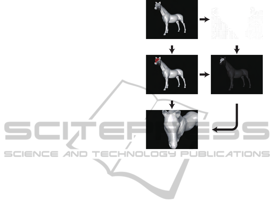
(a) 3D view (b) Depth buffer
(c) Paint (red) (d) Region of Interest
(e) Updated 3D view
Figure 1: An overview of our algorithm.
only view navigation but also collision detection on
GPUs and achieved multi-scale navigation of very
large scenes. These methods are also close to ours,
however their purpose is different. Our method is
designed for viewing and manipulating unstructured
massive scanned models with low FPS.
(Hachet et al., 2008) proposed an excellent in-
terface to select viewpoints. Given a point or circle
strokes as a region by the users, it gives a 3D widget
in the region to control an optimal view. However,
this is difficult to find an optimal viewpoint from cur-
rent view. Although they provide a preview window
to help it, they need to render scenes and it may take
time for massive models.
3 ALGORITHM
The our method interface is quite simple; users simply
paint the region they want to see. Fig. 1 shows an
overview of the algorithm used.
Given a 3D scene (a), the depth buffer (b) is first
captured from the scene. The results of the painting
are stored as a mask image (c), and the depth buffer is
then clipped using this image (d). The region of inter-
est or point set P = {p
i
} is computed by the clipped
depth buffer. Our algorithm computes camera infor-
mation C from P and the current camera information
ˆ
C(e). According to (Blinn, 1988), C includes follow-
VIEWPOINT SELECTION BY PAINTING
297
ing components (Fig. 2):
• e : eye position
• c : center of interest
• u : up vector
• θ : the perspective angle of the camera. In this
paper, we assume that remains unchanged.
Here, we introduce the method of computation.
c
θ
n
u
R
e
ROI
Figure 2: Camera information.
The center of interest is given by taking the
weighted center of mass of P as shown in Eq.1,
c =
1
∑
w
i
∑
p
i
∈P
w
i
p
i
, (1)
where w
i
denotes the area around p
i
. The reason for
introducing w
i
is that corresponding points in 3D are
sampled non-uniformly.
Next, we ascertain the ray vector n for computing
e. It is natural that n is the normal vector of a tangent
plane of P. Here, we use a method for estimating the
normal vector of a point set (Hoppe et al., 1992). We
construct a co-variance matrix M of P in Eq. 2,
M =
∑
p
i
∈P
w
i
(p
i
− c)
T
(p
i
− c). (
2)
We use n as the eigenvectorcorresponding to the min-
imum eigenvalue of M. Then, the direction of n satis-
fies (n,
ˆ
n) > 0, where
ˆ
n denotes the normal vector of
the current scene.
The eye point e can then be reconstructed from c
and n using Eq. 3,
e = c+
R
sinθ
n, (3)
where R and θ denote the radius of bounding sphere of
P and the field of view angle in the current perspective
view, respectively (Fig. 2).
By using n and
ˆ
n, we can obtain a rotation matrix
R such that n = R
ˆ
n. The up vector u is computed by
R using Eq. 4,
u = R
ˆ
u. (4)
Finally, the camera position is updated by the
graphics API (e.g., gluLookAt()).
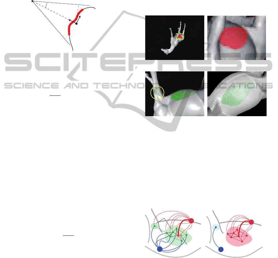
3.1 Outlier Removal
Our algorithm is weak with irregular points (outliers)
(shown in the yellow circle in Fig. 3(c)) caused by
mispainting (Fig. 3(a) and (b)) or scanning noises
because they affect the covariance matrix in Eq. 2,
and invalid ray vectors are computed (Fig. 3(c)). Of
course, such points can be removed by erasing the
paint, but we introduce an automatic removal method
using global optimization solutions such as graph-cut
(Boykov and Kolmogorov, 2004).
(a) Over-painting (b) Close-up view of (a)
(c) Result w/o graph-cut (d) Result with graph-cut
Figure 3: Outlier removal by graph-cut segmentation. The
green spheres are 3D points unprojected from depth buffers.
The graph-cut algorithm is a minimum-cut algo-
rithm for graphs (Fig. 4), and is widely used in im-
age processing problems. We use it to automatically
remove outliers caused by mispainting (Fig.3 (c)).
However, cost assignment is a difficult task. Here,
we discuss a strategy to assign costs between nodes
for graph-cut application.
8
1
α
v
i
v
j
S
T
Sink node
Source node
U
F
(a) Cost setting
Outlier
Correct ROI
(b) Minimum cut
Figure 4: Graph cut segmentation in outlier removal.
From observation of Fig. 3 , we can draw the follow-
ing assumptions:
1. The mispainted region is relatively small, and cre-
ates small clusters (Fig. 4(a)).
GRAPP 2011 - International Conference on Computer Graphics Theory and Applications
298
2. The depth value of the mispainted region is sig-
nificantly different from that of the correct region.
From assumption 1, we can extract a point set F =
{f
i
} that must belong to the correct ROI (Fig. 4
(a)). These can be obtained by taking the k-th nearest
points from the median of the depth buffers in P. The
other points U = {u
i
} are considered as unknown.
Now we assign a weight to each edge between v
i
and
source/sink nodes as shown in Eq. 5,
w(v
i
, S) =
∞ v
i
∈ F
1 v
i
∈ U
,
w(v
i
, T) =
0 v
i
∈ F
α v
i
∈ U
, (5)
where S and T are the roots of the source and sink
nodes respectively. α is a parameter to control the
results.
Next, we assign a weight to each edge between
neighboring nodes v
i
and v
j
based on assumption 2.
If two nodes are close to each other, they are hard to
cut and their cost must be low and vice versa. The
cost function between nodes is given by Eq. 6.
E(v
i
, v
j
) =
β
||v
i
− v
j
||
, (6)
where β is a user-given parameter.
Fig. 3 shows an example. Here, the user intends
to paint the body of the horse model. We apply graph-
cut in the preprocessing phase to remove such noise
before the viewpoint computation phase. It is seen
that the expected results can be computed as a result
of outlier removal from Figure 3(d). In this case, α =
10 and β = diag(P) : diagonal length of the bounding
box of P used.
4 RESULTS AND DISCUSSION
4.1 Implementation
We implemented a prototype system with OpenGL
and GLUT. Note that this algorithm can be imple-
mented without any special functions. For instance,
glReadPixels() is used to capture depth buffers, and
gluUnproject() is used to compute 3D points from
depth values. This means the algorithm does not re-
quire expensive GPUs.
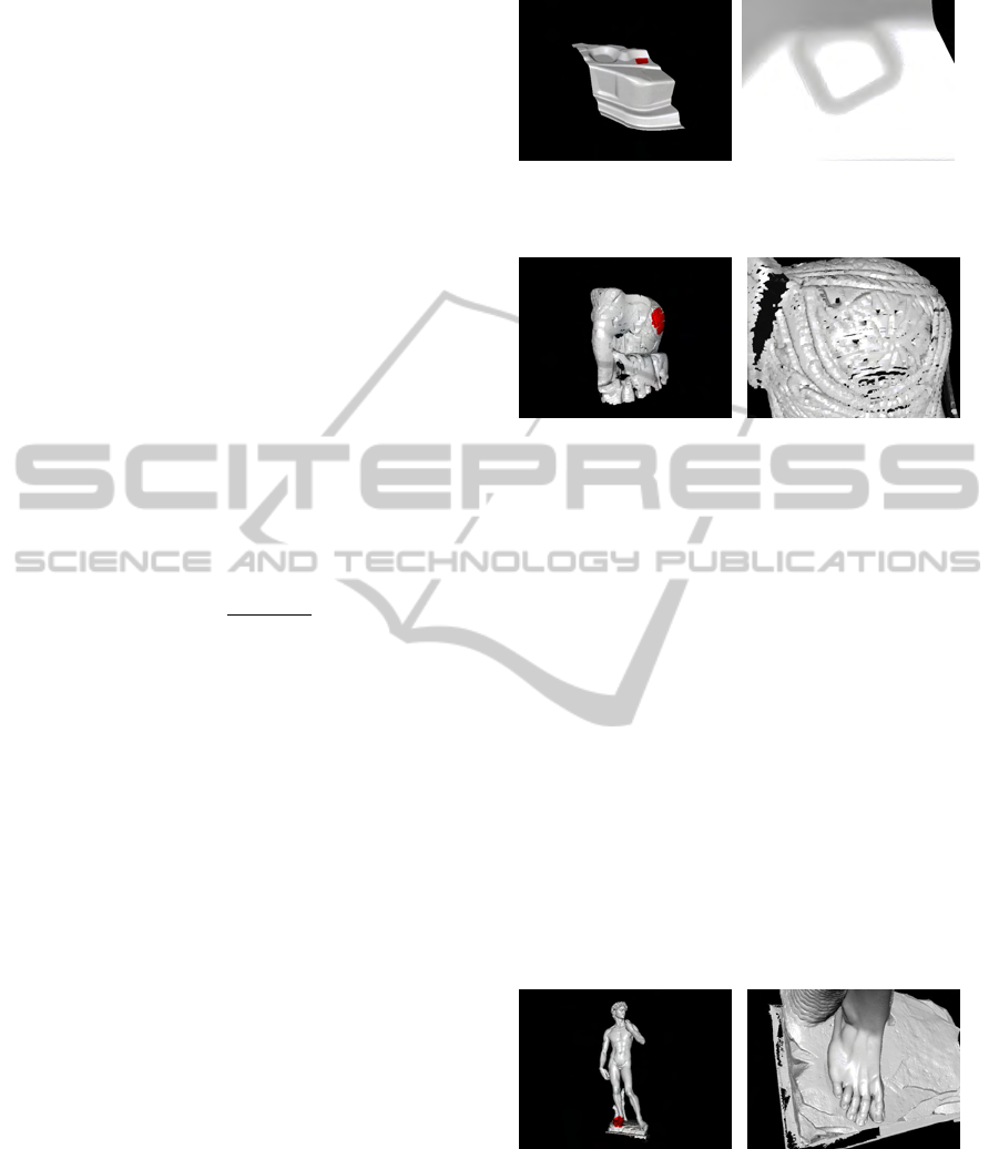
4.2 Results
Figs. 1, 5, 6 and 7 show several results obtained using
our method. In each figure, (a) shows the input cam-
era position with the ROI drawn in red, and (b) shows
the reconstruction resulting from this technique.
(a) (b)
Figure 5: Results for scanned objects(120,303 triangles).
(a) (b)
Figure 6: Results for a scanned point set (1,282,225 points).
4.3 Discussion
Figs. 1, 5, 6 and 7 demonstrate results for point sets
and polygons. These figures show that our method
can be applied to various types of geometric mod-
els. This is because geometry is captured from depth
buffers, and intersections between rays and objects
are not considered.
Our method retrieves geometry from depth
buffers, and does not render during the navigation
phase. This means that there are not gaps between
user action and display results even with massive
models. Fig. 7 shows a model of David with over ten
million triangles. With such complex models, it usu-
ally takes a long time to reach the desired position.
However, our method achieves appropriate position
with a single user action.
(a) (b)
Figure 7: Results for complex models(11,169,874 trian-
gles).
Fig. 8 shows computational statistics for finding
viewpoint described in Section 3. All examples are
measured in the following environments :
• 32 bit : Intel Core 2 Duo 2.13GHz + GeForce
7300GS (521MB)
VIEWPOINT SELECTION BY PAINTING
299
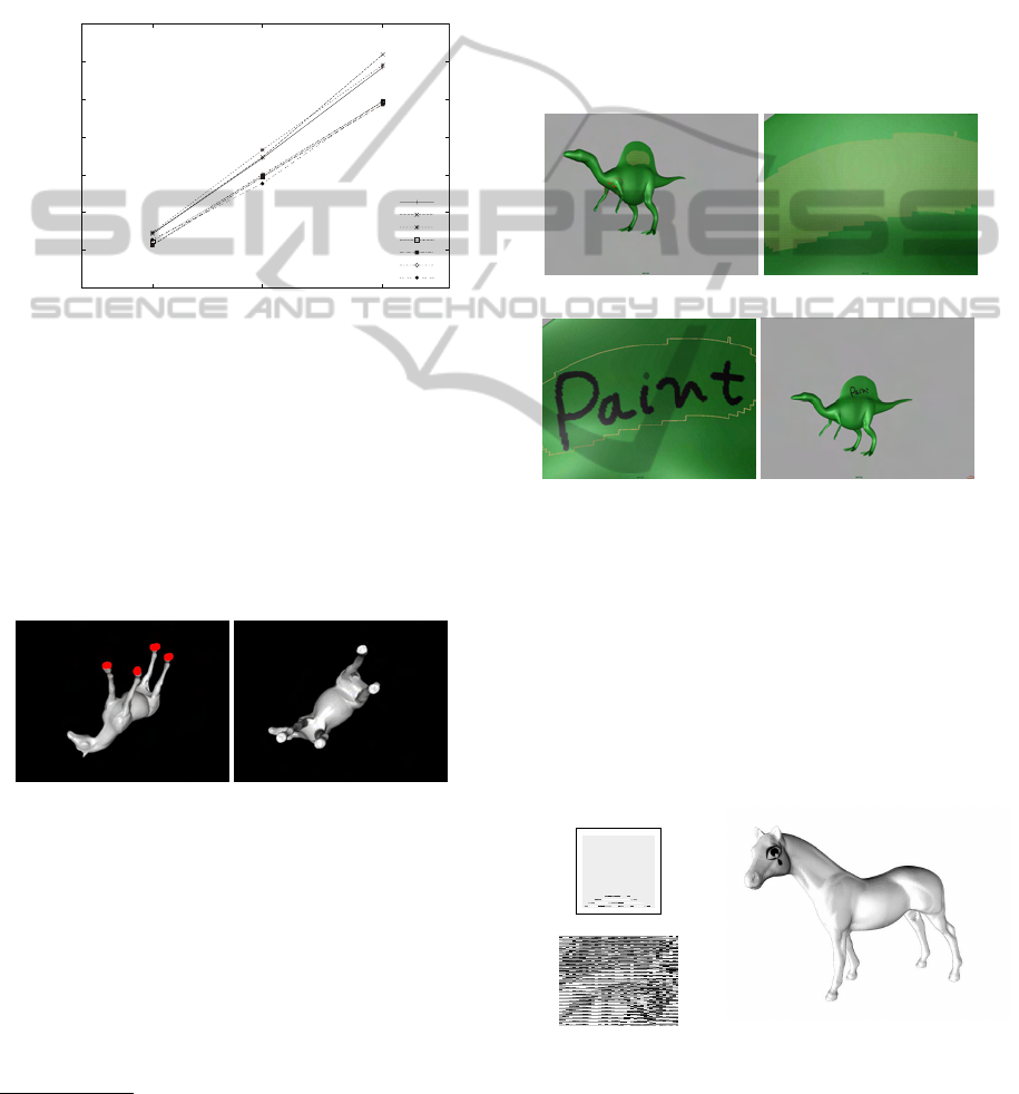
• 64 bit : Intel Xeon 3.16GHz + QuadroFX 1700
(512MB)
Note that the David model cannot be rendered on a
32-bit OS due to memory allocation error. We can see
computation time for each example is almost same,
although the number of elements is different. On the
other hand, the size of the frame buffer affects per-
formance because it takes much time to retrieve the
depth buffer.
0
0.5
1
1.5
2
2.5
3
3.5
640x480 1024x768 1280x1024
Computation time (sec.)
Resolution of frame buer
Elephant
CAD mesh
Horse
Elephant(x64)
CAD mesh(x64)
Horse(x64)
David(x64)
Figure 8: Statistics.
One of advantages of paint-based interface is to
specify complex ROIs as shown in Fig. 9. In this ex-
ample, we paint four soles of the horse model(a), and
our method computes the viewpoint so that we can see
them at once(b). Note that other methods(rectangle
and cursor) cannot work well. This is because they
capture unnecessary region, and invalid viewpoint
will then be computed.
(a) Paint (b) Result
Figure 9: Focus on multiple ROIs.
The quality of C depends on that of the depth
buffer. If the near and far clipping planes are far from
each other, the precision of the depth value is worse
when the surface is close to the far clipping plane
1
.
Accordingly, we need to consider clipping plane man-
agement to ensure a tight fit to the model. This can be
resolved by finding min/max depth values and using
them as clipping planes.
1
http://www.opengl.org/resources/faq/technical/
depthbuffer.htm
5 APPLICATIONS
5.1 3D Painting and Sketching
Direct painting and sketching onto 3D surfaces is an
intuitive method for the modeling process. Accord-
ingly, it is better for capturing and focusing on sur-
faces on which users paint or sketch. Fig. 10 shows a
framework of 3D painting with our method interface
implemented in Autodesk Maya. A good viewpoint
for 3D painting can be obtained through this method
with a single user action, thus accelerating the paint-
ing process.
(a) Painting (b) Updated viewpoint
(c) Painting on the surface (d) Result. Back to (a)
Figure 10: Framework of 3D painting with our method.
This technique can be used not only for painting
and sketching but also for decal arrangement. Since
decal placement uses projection mapping, it is diffi-
cult to achieve the desired direction when mapping
decals onto curved or bumpy surfaces. Fig. 11 shows
an example of decal arrangement in Maya. Here, we
map a decal texture (a) onto the left eye of a horse
model (b). our method is used to compute the projec-
tion plane.
(a) Decal (512x512)
(b) Mapping (c) Result
Figure 11: Example of decal arrangement with our method.
GRAPP 2011 - International Conference on Computer Graphics Theory and Applications
300

5.2 Light Placement
Our algorithm can also position lights appropriately
(Fig. 12). The interface is almost the same as that for
camera placement. The user paints the region where
the light is needed, and the algorithm creates a spot-
light to illuminate the area specified. The light posi-
tion, the direction and cut-off ratio for the spot light
correspond to the e, n and θ in Section 3 respectively.
This is efficient for CG animations. In CG production,
there is often a need to place lights in an eccentric po-
sition to obtain plausible shading.
(a) Painting ROI (b) Lighting result
Figure 12: Light placement by painting.
6 CONCLUSIONS
We have presented a painting interface for camera
placement. Our algorithm requires only specification
of the region of interest by painting, and the cam-
era is then repositioned based on the ROI. We remark
that our method is not the alternative of other existing
methods, and we suppose to use the proposed method
with them. For instance, we use our method for find-
ing intial viewpoint and we adjust the viewpoint by
other methods(e.g. zoom out).
We also have plans for related future work. First,
the good up vector need to be computed. Second, we
would like to extend this method to volumetric mod-
els or we would like to find a viewpoint by direct
painting on volume rendering display.
ACKNOWLEDGEMENTS
Models are cortesy of Georgia Tech(Fig.1),
AIM@shape(Fig. 6) and Stanford Digital Michelan-
gelo Project (Fig. 7). This work is partially suppoted
by KAKENHI (No. 22246018, No. 22700091).
REFERENCES
Blinn, J. (1988). Where Am I? What Am I Looking At?
IEEE CG&A, 8(4):76–81.
Bordoloi, U. D. and Shen, H.-W. (2005). View selection for
volume rendering. IEEE Visualization, 0:487–494.
Boykov, Y. and Kolmogorov, V. (2004). An experimental
comparison of min-cut/max-flow algorithms for en-
ergy minimization in vision. IEEE PAMI, 26(9):1124–
1137.
Chen, M., Mountford, S. J., and Sellen, A. (1988). A study
in interactive 3-d rotation using 2-d control devices.
In SIGGRAPH ’88, pages 121–129.
Foskey, M., Otaduy, M. A., and Lin, M. C. (2002). Artnova:
Touch-enabled 3d model design. In IEEE Virtual Re-
ality, page 119.
Fu, H., Cohen-Or, D., Dror, G., and Sheffer, A. (2008). Up-
right orientation of man-made objects. ACM Transac-
tions on Graphics, 27:42:1–42:7.
Hachet, M., Decle, F., Kn¨odel, S., and Guitton, P. (2008).
Navidget for easy 3d camera positioning from 2d in-
puts. In Proceedings of IEEE 3DUI, pages 83–88.
Hoppe, H., DeRose, T., Duchamp, T., McDonald, J., and
Stuetzle, W. (1992). Surface reconstruction from un-
organized points. In SIGGRAPH ’92, pages 71–78.
Kamada, T. and Kawai, S. (1988). A simple method
for computing general position in displaying three-
dimensional objects. Comput. Vision Graph. Image
Process., 41(1):43–56.
Khan, A., Komalo, B., Stam, J., Fitzmaurice, G., and
Kurtenbach, G. (2005). Hovercam: interactive 3d nav-
igation for proximal object inspection. In I3D ’05,
pages 73–80, New York, NY, USA. ACM.
Lee, C. H., Varshney, A., and Jacobs, D. W. (2005). Mesh
saliency. In ACM SIGGRAPH 2005 Papers, pages
659–666.
McCrae, J., Mordatch, I., Glueck, M., and Khan, A. (2009).
Multiscale 3d navigation. In I3D ’09, pages 7–14,
New York, NY, USA. ACM.
Podolak, J., Shilane, P., Golovinskiy, A., Rusinkiewicz, S.,
and Funkhouser, T. (2006). A planar-reflective sym-
metry transform for 3d shapes. In ACM SIGGRAPH
2006 Papers, pages 549–559.
Shoemake, K. (1992). Arcball: a user interface for speci-
fying three-dimensional orientation using a mouse. In
Graphics interface ’92, pages 151–156.
Takahashi, S., Fujishiro, I., Takeshima, Y., and Nishita, T.
(2005). A feature-driven approach to locating optimal
viewpoints for volume visualization. IEEE Visualiza-
tion, 0:495–502.
VIEWPOINT SELECTION BY PAINTING
301
