
DYNAMIC AND ADAPTIVE TESSELLATION
OF B
´
EZIER SURFACES
R. Concheiro, M. Amor
University of A Coru
˜
na, A Corua, Spain
M. B
´
oo
University of Santiago de Compostela, Santiago de Compostela, Spain
montserrat.boo@usc.es
M. Doggett
Lund University, Lund, Sweden
Keywords:
Adaptive tessellation, GPU, B
´
ezier surfaces.
Abstract:
B
´
ezier surfaces offer powerful mechanisms to describe high quality models in computer graphics. In this
paper we present a methodology for the implementation of the adaptive tessellation of B
´
ezier models on the
GPU. Tessellation is performed with variable resolution inside the patch to permit the use of meshes with a
lower number of triangles but preserving a high visualization quality. Primitives are dynamically generated
according to the results of local subdivision tests. The locality of the decisions assures that contiguous triangles
are coherently subdivided.The resulting procedure is efficient, simple and generates the tessellation pattern of
each B
´
ezier surface dynamically. This enables tessellation of complex models to be performed in real time.
1 INTRODUCTION
B
´
ezier representations have been widely employed as
a standard way of designing complex scenes with very
good quality results. In many applications involving
CAD/CAM, virtual reality, animation and visualiza-
tion, object models are described in terms of B
´
ezier
surfaces. The excellent mathematical and algorithmic
properties (Piegl and Tiller, 1997), combined with
successful industrial applications, have contributed to
the popularity of this representation.
Traditionally, for the rendering process the B
´
ezier
models are tessellated on the CPU (Central Process-
ing Unit) and the set of generated triangles is sent to
the GPU (Graphic Processing Unit). The CPU-GPU
bus can become a bottleneck in this approach due to
the large number of triangles generated for high qual-
ity models. Nowadays, there are some approaches
to perform the tessellation of the parametric models
directly on the GPU. In these proposals the tessella-
tion level is selected per patch (Guthe et al., 2005;
Concheiro et al., 2010) or per set of patches (Dyken
et al., 2009). Another tessellation approach is presen-
ted in (Eisenacher et al., 2009; Schwarz and Stam-
minger, 2009) where the tessellation is performed fol-
lowing a GPGPU strategy (General-Purpose Compu-
tation on GPU). In a similar way, all these proposals
are adaptive at the patch level, that is, once the resolu-
tion for a patch is determined, the patch is subdivided
in a uniform way (with specific modifications in the
border of the patch to assure no holes or cracks be-
tween neighbor patches).
Until recently, the programmable vertex and pixel
shaders found in GPUs could only operate on existing
data. The scene changed a few years ago with the in-
troduction of a new programmable unit, the geometry
shader and the introduction of new tessellation stages
(hull shader, tessellator and domain shader) (Ni and
Casta
˜
no, 2009). Some adaptive tessellation proposals
for triangles meshes exploiting geometry shader have
been developed (B
´
oo et al., 2011; Lorenz and D
¨
ollner,
2008) and no one, as far as we know, is focused on the
adaptive tessellation of parametric models at the trian-
gle level. The scene did not change with the introduc-
tion of the new tessellator unit because it applied a
fixed and semi-regular pattern also at the patch level.
100
Concheiro R., Amor M., Bóo M. and Doggett M..
DYNAMIC AND ADAPTIVE TESSELLATION OF BÉZIER SURFACES.
DOI: 10.5220/0003361001000105
In Proceedings of the International Conference on Computer Graphics Theory and Applications (GRAPP-2011), pages 100-105
ISBN: 978-989-8425-45-4
Copyright
c
2011 SCITEPRESS (Science and Technology Publications, Lda.)

Tessellation
Pattern
Test
Unit
Mesh
Unit
Initial
triangle
Sampling
points
Inserted
vertices
Final
triangles
L=3
Figure 1: Scheme of the DABT algorithm.
In this paper we present a new method to adaptively
tessellate B
´
ezier surfaces on the GPU. Our Dynamic
and Adaptive B
´
ezier Tessellation (DABT) proposal
permits the minimization of the number of triangles
to be processed without reducing the quality of the fi-
nal images. To increase the adaptive properties of pre-
vious proposals, neighbor triangles can be tessellated
with a different resolution without cracks. Therefore,
our method tessellates B
´
ezier surfaces in an adaptive
way, so real-time rendering of complex models can be
achieved.
2 DYNAMIC AND ADAPTIVE
B
´
EZIER TESSELLATION
In this section we present our Dynamic and Adap-
tive B
´
ezier Tessellation (DABT) proposal. Our strat-
egy performs the adaptive tessellation of the B
´
ezier
surface by computing the tessellation pattern on-the-
fly without employing a set of pre-computed patterns.
The objective is a freely adaptive tessellation inside
each patch where the resolution and number of tri-
angles generated can be selected as a trade off be-
tween quality and computational requirements. The
methodology we propose is based on local tests, the
resulting model has no cracks or holes, neither inside
each patch nor between neighbor patches.
Specifically, our DABT method is based on three
different key proposals: the utilization of a fixed tes-
sellation pattern that guides the adaptive tessellation,
the application of local tests and an efficient meshing
procedure to reconstruct the resulting mesh once the
tests are applied. Figure 1 schematically shows these
three key cores of the algorithm.
2.1 Utilization of a Fixed Pattern to
Guide the Adaptive Tessellation
Procedure
The objective of the proposal is to exploit the large
number of cores available in current GPUs. With this
objective in mind the patches of the model are initially
tessellated and the coarse triangles employed as input
primitives for the application.
Tessellation algorithms with a recursive nature
have different disadvantages. For this reason the
V1
V3
V2
E1,2
E1,3
E2,3
Figure 2: Example of triangle with three different resolution
areas.
DABT method employs a non recursive strategy
based on the utilization of a non adaptive tessella-
tion pattern as a basis for the adaptive case. Once
the tessellation level of the pattern is selected only the
positions in this tessellation pattern are evaluated for
conditional insertion at each position.
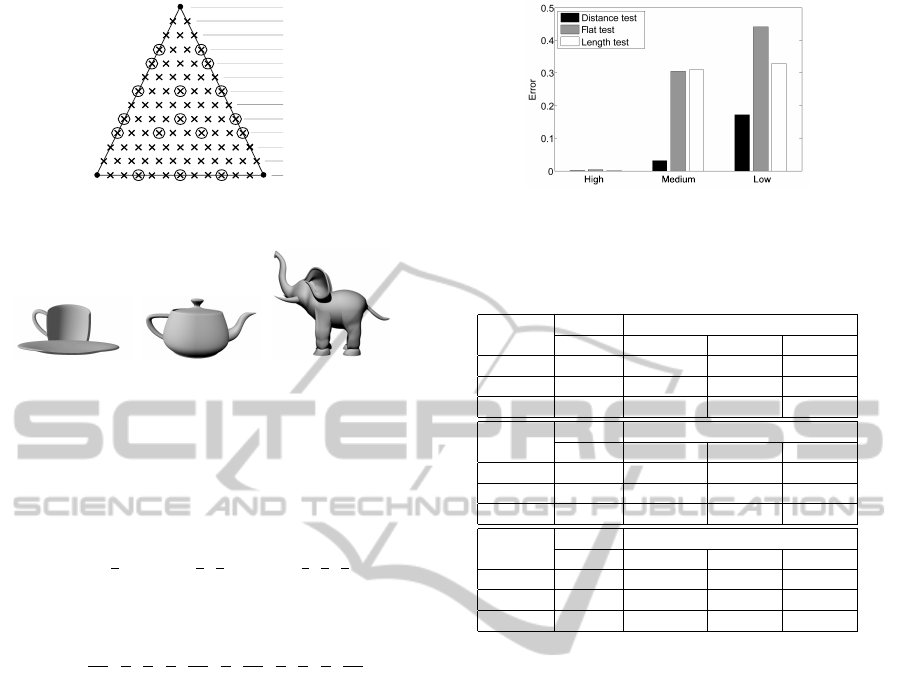
Figure 1 shows the tessellation patterns we em-
ploy for a level of resolution L = 3. The origi-
nal coarse triangle is depicted with bold lines and
the sampling points corresponding to the candidate
vertices with a cross. The parametric coordinates
(u
B
, v
B
) of the sampling point associated with a can-
didate vertex V
B
that lies on the B
´
ezier surface are
computed through its barycentric coordinates with:
V
B
(w
i
, w
j
, w
k
) = w
i
× (u
1
, v
1
) + w
j
× (u
2
, v
2
+ w
k
×
(u
3
, v
3
)), where (u
1
, v
1
), (u
2
, v
2
) and (u
3
, v
3
) are the
parametric coordinates of the vertices of the initial
coarse triangle and (w
i
, w
j
, w
k
) are the barycentric co-
ordinates of the candidate vertex. The barycentric val-
ues are in the interval [0, 1] and verify w
i
= i · δw,
w
j
= j · δw and w
k
= k · δw with i, j, k = 0, ...L + 1
and δw =
1
L+1
.The tessellation is performed in the
parametric domain, for the specific case of a bi-cubic
B
´
ezier surface the following equation is evaluated:
Q(u, v) = [u
3
u
2
u 1]
−1 3 −3 1
3 −6 3 0
−3 3 0 0
1 0 0 0
B
0,0
B
0,1
B
0,2
B
0,3
B
1,0
B
1,1
B
1,2
B
1,3
B
2,0
B
2,1
B
2,2
B
2,3
B
3,0
B
3,1
B
3,2
B
3,3
−1 3 −3 1
3 −6 3 0
−3 3 0 0
1 0 0 0
v
3
v
2
v
1
(1)
In order to enrich the adaptive tessellation possibil-
ities, we have developed a method for the assigna-
tion of different resolution levels to neighbor trian-
gles. With this non uniform approach, the resolution
level can be dynamically selected and modified along
the patch. Specifically a resolution level is selected
per triangle edge so one triangle could have three res-
olution levels. In order to apply three levels per tri-
angle, each one would be applied to one third of the
triangle. Figure 2 shows a triangle where three differ-
ent resolution levels coexist. In this example the area
DYNAMIC AND ADAPTIVE TESSELLATION OF BÉZIER SURFACES
101

E
1,2
follows a tessellation pattern L = 3 that means
that three rows of candidate vertices have to be ana-
lyzed. Area E
1,3
is subdivided according to a tessella-
tion pattern L = 2, that is, two rows of candidate ver-
tices have to be considered. Finally, E
2,3
is tessellated
with a resolution level L = 1.
2.2 Tests Employed to Guide the
Adaptive Tessellation
The candidate vertices are conditionally inserted ac-
cording to the result of specific tessellation tests
(see Figure 1). We have evaluated different tests to
guide the tessellation procedure. These tests measure,
through the utilization of different quality thresholds,
the increment of quality of the mesh if a given vertex
is inserted.
2.2.1 Distance Test
This test analyzes the distance between the triangle
mesh and the B
´
ezier surface. Specifically the distance
between a sampling point on the triangle mesh and the
corresponding point on the B
´
ezier surface is analyzed.
If the distance is small enough, the triangle mesh is
considered a good approximation of the surface so no
vertex is inserted. On the contrary, if the distance is
large the vertex is introduced as this will increase the
quality of the final image. The test is given by:
distance = [|V
S
−V
B
| > t
distance
]
where t
distance
is a quality threshold that is selected
in function of the quality/timing requirements of the
application, V
S
is the corresponding sampling point
on the coarse triangle by interpolating the position of
the original vertices and V
B
is the coordinates of the
candidate vertex on the B
´
ezier surfaces obtained by
using Equation 1.
2.2.2 Vector Deviation Flat Test
The objective of this test is employing the curvature
of the surface as a parameter to guide the tessellation
procedure. With this test candidate vertices on flat
areas are not considered for insertion as the quality of
the surface would not be incremented. To check the
curvature of the surface a simple vector deviation flat
test (Espino et al., 2007) can be employed.
In order to reduce the costly computation of all
candidate vertices our flatness test follows a per edge
philosophy. In our proposal each candidate position
associated with the coarse edges is analyzed and the
decision performed is applied to all candidate posi-
tions of the same row and resolution area.Then, with
this technique the curvature of the surface is estimated
only for the sampling points on the edges of the coarse
triangle and the result are employed in the interior of
the projection. Specifically the test consists of the fol-
lowing steps:
1. Calculation and normalization of vectors A =
|V
1
−V
2
|, B = |V
B
−V
1
| and C = |V
B
−V
2
|, where
V
1
and V
2
are the extreme points of each edge.
2. Computation of the unsigned dot products |BA|
and |CA|
3. Comparison between the dot products and a
threshold, t
f lat
. If one of them is smaller than the
threshold, the new vertex is inserted:
f lat = (|BA| < t
f lat
) OR (|CA| < t
f lat
)
2.2.3 Length Test
In geometric design applications rather than using a
very high degree surface to approximate a very com-
plex surface, it is more common to break the surface
up into several simple surfaces. Specifically, the test
is based on the utilization of the length of the coarse
triangle edges as a measure of the curvature of the
B
´
ezier surface in the corresponding area.
Due to low degree of each B
´
ezier surface and as
the vertices of the coarse triangle mesh lie on the sur-
face, if the coarse triangle is small then it can be con-
sidered a good approximation to the surface. Specifi-
cally, if the two vertices of one edge are close enough,
the inclusion of additional vertices on that edge will
not increase the quality of the final mesh.
This test works on the edge basis as it is only
applied for the sampling points on the edges of the
coarse triangle. In case a vertex corresponding to the
the edge is inserted, the vertices on the same row are
directly inserted. Note that the test is based on the
analysis of the original vertices of the triangle and
does not require the computation of the candidate ver-
tices. The computational requirements of this new test
are very low.
To test if a candidate vertex V
B
has to be inserted in
the edge with vertices V
1
and V
2
the following analysis
is performed:
length = (|V
1
−V
S
| > t
length
) AND (|V
2
−V
S
| > t
length
)
that means that the point V
B
is inserted only when the
distance of the corresponding sampling point on the
triangle V
S
to both extreme vertices V
1
and V
2
is larger
than a threshold t
length
.
2.3 Tessellation Procedure
In this section, we describe the tessellation proce-
dure employed to generate the final triangles once the
GRAPP 2011 - International Conference on Computer Graphics Theory and Applications
102

inserted vertices have been determined (see Figure
1). A similar strategy was employed in (B
´
oo et al.,
2011) for the adaptive tessellation of generic triangle
meshes. This tessellation procedure is based on the
classification of the inserted vertices in strips and the
efficient management of the resulting list of vertices.
The objective in mind is generating the triangle struc-
ture in a direct way from the irregular pattern obtained
with the evaluation of the subdivision tests.
As the non adaptive tessellation patterns are char-
acterized by a row structure, our algorithm inher-
its this characteristic and classifies the resulting in-
serted vertices in rows. A tuple of L + 2 lists Sv =
(Sv
1
, ··· , Sv
L+2
) corresponding to the L + 2 strips of
vertices used. Each list includes the vertices inserted
in each strip and positions of non-inserted vertices are
empty. An example of adaptive tessellation is de-
picted in Figure 3(a) where the candidate positions
are labeled with numbers and the vertices finally in-
serted are indicated with dots. In this case, the final
tessellation pattern can be represented with the fol-
lowing lists: Sv
1
= {1}, Sv
2
= {}, Sv
3
= {4, 5, 6},
Sv
4
= {9, 10}, Sv
5
= {11, 13, 15}
The objective is generating the final triangles by
connecting the vertices in two consecutive lists. How-
ever the direct application of this technique would
lead to the generation of undesired overlapping tri-
angles. To avoid this problem, two modifications are
introduced to the representation: reuse of limit ver-
tices and incorporation of new extreme vertices. A
limit vertex is a vertex located in the original edge of
the triangle. If such a vertex does not exist, an ex-
treme vertex is the first/last vertex in the list. With
respect to the modification related with the limit ver-
tices, if there is no limit vertex in a row a limit vertex
from a previous row has to be included. As an exam-
ple for the list of vertices corresponding to Figure 3(a)
this modification implies that the Sv
4
list has to be ex-
tended as Sv
4
={
ˆ
4, 9, 10} where the reused limit vertex
is indicated with a hat. The reuse of limit vertices per-
mits the generation of triangles connecting vertices in
non consecutive rows. As a consequence and in or-
der to avoid an overlap of these large triangles with
other local structures, the incorporation of new ex-
treme vertices are required. A detailed explanation
can be found in (B
´
oo et al., 2011).
The tessellation procedure works by processing
pairs of consecutive strips of vertices. In this method
the triangles are generated by joining the vertices
between consecutive strips (parent-children relation)
taking into account the following rules:
• Two consecutive vertices in the same strip are al-
ways connected (sibling relation).
• Two identical vertices are not considered for con-
1
2 3
4 5 6
7 8 10
11
12 13 14 15
9
(a)
1
4 5 6
10
11
13
14
15
9
(b)
Figure 3: Example of mesh reconstruction: (a) Vertices in-
serted. (b) Tessellation generated.
nection.
• A reused opening/closing limit vertex has a lim-
ited connection with the following non empty
strip. Specifically, it can only be connected with a
non-copied opening/closing limit vertex.
• Each non reused vertex of each strip, considered
as parent, is connected with consecutive children
in the following strip. The following parent is
connected with another group of consecutive chil-
dren. There is an overlap of one common child
between two consecutive parents.
The application of these rules to each pair of extended
vertex lists generates the final tessellation.
3 IMPLEMENTATION ON THE
GEOMETRY SHADER
Our implementation processes bi-cubic B
´
ezier sur-
faces and exploits the capabilities of the geometry
shaders that permit a fully adaptive tessellation. How-
ever, the main drawback of the geometry shader is the
limitation of the number of output primitives per in-
vocation, as currently only 1024 32-bit values can be
output.
The patches of the model are initially tessellated
and the resulting coarse triangles are employed as in-
put primitives for the application. To do this, the para-
metric domain (u, v) is partitioned in N
u
× N
v
cells of
size
1
N
u
×
1
N
v
where two adjoining triangles are gener-
ated per cell.
Once the coarse mesh is extracted, the adaptive
tessellation algorithm is applied to each coarse tri-
angle. As was previously indicated, the tessellation
procedure is based on the utilization of a non adap-
tive pattern to guide the tessellation. Our implemen-
tation is based on the row structure of the tessel-
lation pattern so some modifications had to be per-
formed to permit the processing of three resolution
areas per triangle. A unified resolution is selected
and employed. For a system with resolution levels L=
(0, ··· , L
max
), the unified resolution level corresponds
with the least common multiple of (0, ··· , L
max
+ 1)
DYNAMIC AND ADAPTIVE TESSELLATION OF BÉZIER SURFACES
103
s1
s2
s3
s4
s5
s6
s7
s8
s9
s10
s11
s12
s13
Figure 4: Unified resolution L
uni f ied
=11 for a system with
L=0,1,2,3.
(a) (b) (c)
Figure 5: Models employed: (a) Teacup, (b) Teapot and (c)
Elephant.
minus 1. As an example let us consider a system with
resolutions L=(0, 1, 2, 3), in this case the unified reso-
lution level is L
uni f ied
= 11. The barycentric weights
employed for the candidate vertices for each resolu-
tion are:w
1
=
1
2
w
2
=
1
3
,
2
3
w
3
=
1
4
,
1
2
,
3
4
being
w
L
the weights employed for level L. The unified sys-
tem of weights is:
w
11
=
1
12
,
1
6
,
1
4
,
1
3
,
5
12
,
1
2
,
7
12
,
2
3
,
3
4
,
5
6
,
11
12
where w
1
0
= w
3
1
= w
12
5
, w
2
0
= w
12
3
, w
2
1
= w
12
7
, w
3
0
= w
12
2
and w
3
2
= w
12
8
. As result, a unified system of weights
and rows can be employed for any resolution level.
Figure 4 shows the tessellation pattern for L
uni f ied
=
11. In fact, the test unit processes only the points asso-
ciated with the resolution level selected. In the figure
the points corresponding to L=1 (lines s7 and s13),
L=2 (lines s5, s9 and s13) and L=3 (lines s4, s7, s10
and s13) are indicated with circles.
4 RESULTS
In this section we present the results of the evaluation
of our proposal in terms of the quality of the final im-
age and frames per second (fps). We have evaluated
our proposal on an Intel Core 2 2.4 GHz with 2 GB of
RAM and an ATI Radeon 5870.
The models employed in the tests presented in this
section are shown in Figure 5: Teacup in Figure 5 (a),
Teapot in Figure 5 (b) and Elephant in Figure 5 (c).
The scenes we have employed for our tests contain
replicated and scaled versions of these models.
Low
High
Medium
Figure 6: Error obtained with the teacup model for L
max
= 3
and three different quality levels.
Table 1: Number of triangles generated with the different
tests presented and L
max
= 3.
High Quality
Scene\Test # surfaces Distance test Flat test Length test
Teacups 260 (10) 72.96 k 70.94 k 71.22 k
Teapots 960 (30) 267.63 k 217.24 k 266.28 k
Elephants 8110 (10) 2034.082 k 1918.933 k 2266.391 k
Medium Quality
Scene\Test # surfaces Distance test Flat test Length test
Teacups 260 (10) 57.49 k 57.69 k 43.15 k
Teapots 960 (30) 257.9 k 195.34 k 208.10 k
Elephants 8110 (10) 1986.02 k 1635.84 k 1781.87 k
Low Quality
Scene\Test # surfaces Distance test Flat test Length test
Teacups 260 (10) 15.1 k 14.49 k 15.44 k
Teapots 960 (30) 135.79 k 126.40 k 142.83 k
Elephants 8110 (10) 742.64 k 497.44 k 559.94 k
Table 1 summarizes the results obtained in terms
of number of primitives. For the tests summarized in
this table, L
max
= 3 and three quality sets of thresholds
were employed: High, Medium and Low.The second
column includes the number of B
´
ezier surfaces per
scene and the number of models replicated. The third,
fourth and fifth columns include the average number
of generated triangles with each test presented in Sec-
tion 2.2.
The tests we have performed indicate that the tes-
sellation method produces high quality meshes with
no visual artifacts. Additionally the multiresolution
method employed and the utilization of multiple res-
olution areas per triangle have produced the expected
good results. Figure 6 shows the mesh errors for
a resulting scene (teacup), with a resolution level
L
max
= 3 for three different quality levels. As it can
be observed and as expected the best results are ob-
tained with the Distance test. This is due to the fact
that it is the unique test performed per candidate posi-
tion instead of per edge and, as a result, higher quality
is obtained. Very close results are obtained with the
Length test while worse results are obtained with the
Flat test. Both tests are performed per edge and the re-
sults indicate that for low degree surfaces the Length
test gives a good estimation of the surface curvature.
GRAPP 2011 - International Conference on Computer Graphics Theory and Applications
104

The main objective of the proposal is the real-
time rendering of complex models without reducing
the quality of the final image. With the objective
of testing the timing requirements of the application
we have analyzed a walk-through animation with the
same movement of the camera for all tests. The fi-
nal images have a screen resolution of 1280 × 1024
pixels. Figure 7 shows the results in fps using a res-
olution level L
max
= 3 for a high quality threshold.
The results indicate very good performances in terms
of fps, allowing real-time adaptive tessellation, even
for a high number of triangles. For example, for
the Length Test 284.94 K triangles were rendered at
148.97 fps. Using this card and for a large number of
triangles the Distance test has similar timing require-
ments than the other proposals. This is due to the ex-
ploitation of VLIW with the utilization of short vector
data types (like f loat4) and vector computations.
5 CONCLUSIONS
In this paper we present a new method, Dynamic
and Adaptive B
´
ezier Tessellation (DABT), for the real
time adaptive tessellation of B
´
ezier surfaces on the
GPU. The method is based on the generation of an ini-
tial coarse triangle mesh that approximates the B
´
ezier
surface and the adaptive tessellation of each resulting
triangle in the GPU. The methodology employed per-
mits applying multiple resolutions to the same B
´
ezier
surface. This means that neighbor triangles can be
processed with different resolutions and no visual ar-
tifacts are visible.
The proposal is based on three main strategies: the
utilization of a fixed tessellation pattern to guide the
procedure, the utilization of local tests for the adap-
tive tessellation decisions and an efficient meshing
procedure to reconstruct the resulting meshes. With
respect to the tests employed, we have included in this
work three tests that analyze different surface features
to guide the tessellation.
To test our algorithm and to evaluate the capabili-
ties of current GPUs we have implemented our DABT
algorithm by exploiting the geometry shader unit. The
good results obtained in terms of quality and frames
per second, makes our proposal an interesting candi-
date for its real hardware implementation on future
GPUs.
ACKNOWLEDGEMENTS
This work was supported by the Xunta de Gali-
cia under projects INCITE08PXIB105161PR and
0 10 20 30 40 50
0
200
400
600
800
Number of original triangles (K)
FPS
Distance test
Lenght test
Flat test
Figure 7: FPS with tessellation level L
max
= 3 for a high
quality threshold.
08TIC001206PR, the Ministry of Science and Inno-
vation, cofunded by the FEDER funds of the Euro-
pean Union under the grant TIN2010-16735, and the
Consolidation of Competitive Research Groups ref.
2010/06.
REFERENCES
B
´
oo, M., Amor, M., Concheiro, R., and Dogget, M. (2011).
Dynamic and Adaptive Mesh Refinement on the GPU.
Internal Report.
Concheiro, R., Amor, M., and B
´
oo, M. (2010). Synthesis of
b
´
ezier surfaces. In GRAPP’10: International Confer-
ence on Computer Graphics Theory and Applications,
pages 110–115.
Dyken, C., M., R., and Seland, J. (2009). Semi-uniform
Adaptive Patch Tessellation. Computer Graphics Fo-
rum, 28(8):2255–2263.
Eisenacher, C., Meyer, Q., and Loop, C. (2009). Real-time
View-dependent Rendering of Parametric Surfaces. In
Proceedings of the 2009 Symposium on Interactive 3D
Graphics and Games, pages 137–143.
Espino, F. J., B
´
oo, M., Amor, M., and Bruguera, J. D.
(2007). Hardware Support for Adaptive Tessellation
of B
´
ezier Surfaces Based on Local Tests. Journal of
Systems Architecture, 53(4):233–250.
Guthe, M., Bal
´
azs, A., and Klein, R. (2005). GPU-Based
Trimming and Tessellation of NURBS and T-Spline
Surfaces. ACM Trans. Graph., 24(3):1016–1023.
Lorenz, H. and D
¨
ollner, J. (2008). Dynamic Mesh Refine-
ment on GPU using Geometry Shaders. In Proceed-
ings of the 16-th International Conference in Cen-
tral Europe on Computer Graphics, Visualization and
Computer Vision 2008.
Ni, T. and Casta
˜
no, I. (2009). Efficient Substitues for Sub-
division Surfaces. Exhibition Tech. SIGGRAPH’09
Course Notes, 2009.
Piegl, L. and Tiller, W. (1997). The NURBS Book. Springer.
Schwarz, M. and Stamminger, M. (2009). Fast GPU-based
Adaptive Tessellation with CUDA. Computer Graph-
ics Forum, 28(2):365–374.
DYNAMIC AND ADAPTIVE TESSELLATION OF BÉZIER SURFACES
105
