
AUTOMATIC CONTACTLESS MOBILE FINGERPRINTING
SYSTEM
M. Baier, S. Foret, V. Oliyil Kunnil, M. Paradis, P. Bustos and S. Mil’shtein
Advanced Electronic Technology Center, Department of Electrical and Computer Engineering
University of Massachusetts Lowell, MA 01854, U.S.A.
Keywords: Fingerprinting, Electro-mechanics, Electro-optics, Mobile embedded system, Wireless.
Abstract: Increased security requirements relevant to the worldwide war against terrorism and cyber crime recently
prompted the development of biometric systems for use in identifying individuals at commercial facilities,
border crossings, airports, and government building access points. Fingerprinting is one of the oldest means
of biometric identification; however, the current methods of fingerprint capture carry inherent limitations on
image quality. The current study describes the development of a novel, mobile, and contactless
fingerprinting system. This system combines the advantages of contactless fingerprinting with the ability to
create a digital map of the blood vessels within a finger for use as a second data set for use in biometric
identification. The distinguishing feature of the system is the use of line scanning technology which allows
for the acquisition of nearly distortion-less 180
o
or “nail-to-nail” fingerprints. The study describes a fully
automatic system and assesses the technical aspects of this novel device. We describe the design of the
subsystems: adaptive lighting, optical image formation, power management methods, wireless data transfer,
and subsystem synchronization techniques. We will also discuss the system’s embedded software, which
synchronizes the operation of all subsystems and allows for fingerprint visualization on an onboard touch
screen display.
1 INTRODUCTION
Fingerprint image acquisition is considered the most
critical step of an automated fingerprint
authentication system as it determines the final
fingerprint image quality and therefore the rate of
success of fingerprint recognition. Not long ago, the
rolled-ink technique was widely used to obtain
fingerprint images (Xia, 2003). This involves
coating a finger in ink and then pressing the fingers
surface against a piece of paper. This method has
been slowly replaced by digital fingerprint readers
which can be grouped into two major families: solid-
state and optical (Xia, 2003). The basic idea behind
each capture approach is to generate an image which
will allow for the extraction of accurate fingerprint
ridge data. When capturing a fingerprint using a
solid-state reader, a finger must come in direct
contact with the sensor; however, because the skin
tissue which comprises a fingerprint is elastic, this
“contact based” method can lead to fingerprint
distortion. In (Mil’shtein, 2004) and (Parziale, 2006)
it was demonstrated using contact based methods
that under the pressure of a finger’s own weight,
fingerprint ridge spacing can be distorted by about
20% in the captured image. Forceful contact of the
finger against the scanner produces even more
distortion as can be seen in (Mil’shtein, 2004). The
pressures magnitude and direction is directly
correlated with the degree of distortion captured in
the resulting image, causing an image of the same
fingerprint to change every time it is printed.
Because of this contact distortion, contactless
techniques are the method of choice in any
fingerprinting technology.
There are a number of contactless scanners on
the market today. Most of these systems are
comprised of a standard area-scan camera that takes
a picture of a fingerprint from a known distance.
This method is capable of imaging the flat portion of
the finger without any distortion; however, close
observation of the physical finger’s edges will reveal
that they are somewhat round in shape. These edge
portions of the finger are not perpendicular to the
camera’s CCD, which causes their projection onto
the flat surface of the sensing element to be a
445
Baier M., Foret S., Oliyil Kunnil V., Paradis M., Bustos P. and Mil’shtein S..
AUTOMATIC CONTACTLESS MOBILE FINGERPRINTING SYSTEM.
DOI: 10.5220/0003362004450450
In Proceedings of the 1st International Conference on Pervasive and Embedded Computing and Communication Systems (PECCS-2011), pages
445-450
ISBN: 978-989-8425-48-5
Copyright
c
2011 SCITEPRESS (Science and Technology Publications, Lda.)
distorted representation of the actual finger
(Parziale, 2006). As a result, current research has
been directed to obtain rolled fingerprint equivalents
in a contactless fashion. These fingerprints have
been shown to be fully compatible with current law
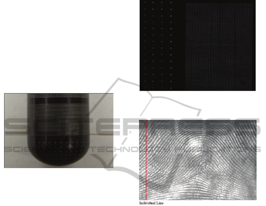
enforcement databases (Yi Chen1, 2006). Figure 1
displays an image of a test finger taken with a
traditional CCD. The test finger has a pattern of dots
arranged in a grid with regular spacing. As expected,
it can be seen that the pattern appears to be
compressed towards the edge of the image due the
fact that the edges of the test finger are “falling
away” from the CCD.
Figure 1: Image of the standard finger emulator with a
traditional CCD. Distortion in the form of compression of
the grid towards the left and right hands of the image can
be seen.
In the current study, the advantages of
contactless imaging techniques are combined with
the very attractive attributes of line-scanning
technology. A two dimensional image of a finger is
recorded in one pixel-thick lines by scanning a line-
scan camera around the finger, completing a 180
o
arc. The image captured represents an uncoiled view
of the finger equivalent to a “rolled ink” print. The
line-scanner views each portion of the finger
perpendicularly, therefore removing the projection
errors inherent in conventional aerial-scanning
techniques. Figure 2 displays an image of the same
test finger shown in figure 1 taken using the line
scanning technique. It can be seen that the
irregularities present in figure 1 are nonexistent, and
the regular spacing’s of the grid pattern have been
preserved.
In such a setup we are able to produce fingerprint
images that are greater than 1000 ppi resolution and
tests of the optical system suggest that the resulting
image is virtually distortion free. Such high
precision allows seeing fingerprint ridges and even
pores in great detail. Figure 3 shows a sample image
taken by our system.
Figure 2: Image of the standard finger emulator taken with
the rotational line scanning approach. Spacing between
the lines is 0.44 mm.
Figure 3: Fingerprint generated by line scan. The solid
line denotes a single line taken by the line scanner.
2 DESCRIPTION
OF MOBILE SYSTEM
2.1 Image Formation
The first step in a fingerprint authentication system
is image capture. In the current study, a nail-to-nail
fingerprint image is captured using the optical setup
shown in figure 4.
The lens system used in this machine is designed
with an overall object-to-image distance of 368mm.
The working distance, which is the distance between
the surface of the finger and the objective lens of the
lens system, is established using the three first-
surface mirrors as seen in Figure 4. First-surface
mirrors are used instead of traditional secondary
surface mirrors to minimize dimming and blurring of
the image that occur as a direct result of light
passing through the glass of a traditional mirror.
PECCS 2011 - International Conference on Pervasive and Embedded Computing and Communication Systems
446
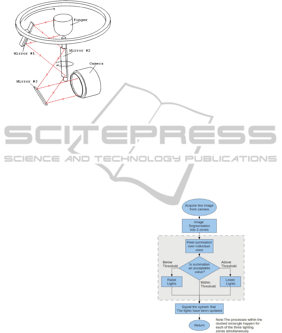
Figure 4: Optical system - arrangement of the mirrors,
camera and finger.
These mirrors direct the image onto the
stationery line-scan camera. Mirror #1 as shown in
figure 4 is mounted onto a rotating turntable. This
turntable allows the mirror to revolve 180
o
concentrically around the finger being imaged.
While rotating, this Mirror (#1) directs the light rays
which are reflected from the fingers surface onto
Mirror #2. Mirror #2 is located directly below and
on axis with the center of the finger. During a scan,
Mirror #2 rotates through a 90
o
sweep within the
same time Mirror #1 completes a 180
o
sweep,
allowing light rays reflected from the finger to
always be focused onto the stationery Mirror #3
which then directs these rays into the camera lens.
The entire scanning procedure takes approximately
¾ of a second. This mirror system greatly reduces
the overall size of the unit to 6”x7”x10” and
minimizes the number of moving parts needed.
The lens system consist of two major parts, the
first is a series of lenses with an effective focal
length of 80mm and the second is a focusing mount
which allows for fine focusing adjustments to the
lens system. This system allows high-resolution
imaging of the fingerprint at resolutions greater than
1000ppi.
The optics, mechanical drive train, and other
components within the scanner are rigidly mounted
within a 6061-T6 aluminum superstructure. The
scanner chassis has been optimized to reduce the
overall weight of the machine, as well as the size of
its construction.
2.2 Lighting Systems
In a typical fingerprint lighting system, illuminators
are aimed at the fingerprint at the start of the scan
and then shut off once a scan is complete (Palma,
2006). This method offers no feedback from the
camera on whether the lighting conditions are
optimal. This can result in washed-out or over
saturated images and the loss of useable information.
For this reason, this scanner utilizes a novel lighting
servo system.
This servo system uses real-time feedback from
the line-scan camera to adjust the lighting intensity
over three separate zones in the fingerprint: top,
middle, and bottom. Every time the scanner’s
processor receives a new line from the line-scan
camera (this happens approximately 1300 times for a
scan at 1000ppi resolution) the line is broken into
three segments: top, middle and bottom. The average
value of the light intensity within each of the three
sections is then computed (pixels in each segment
(numbering N) are summed and the resulting
number is divided by N) and the lighting zone
associated with each of the respective segments (top,
middle, and bottom) is adjusted up or down as
needed. This process is continued until all of the
lines which comprise the fingerprint image have
been taken. This method allows for 3900 different
lighting intensities to be implemented throughout
one scan of 1300 lines, and is visually described
below in figure 5.
Figure 5: Logical flow chart of the contactless
fingerprinter’s lighting servo system. This process is
repeated every time the system receives a new line from
the camera.
2.3 Blood Vessel Mapping
There are well known systems made by Mitsubishi
AUTOMATIC CONTACTLESS MOBILE FINGERPRINTING SYSTEM
447
and Hitachi that use blood vessel mapping as a
primary method of finger identification (Mitsubishi,
2006). In contrast, our system uses blood vessel
mapping as a secondary finger recognition method,
as well as to check the “liveliness” of a finger, or
whether there is blood actively being circulated
within the fingers veins.
IR LEDs are positioned directly behind the
finger and opposite the first imaging mirror. These
provide light that is transmitted through the finger
then recorded via the same line-scan camera used in
fingerprinting. This feature allows for a second basis
of comparison for an individual, and increases the
overall reliability of identification (Nixon, 2005).
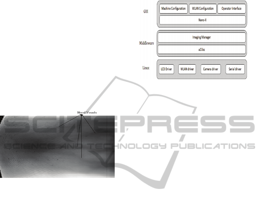
Figure 6 presents an example of an unprocessed
view of blood vessels in a finger.
Figure 6: Image of blood vessels produced by IR light
transmitted through the finger. The image was recorded by
a line-scan camera.
2.4 Processor
The current system uses an OMAP35X processor
running Linux kernel version 2.6.31. This processor
is ideally suited for handheld, high level computing
applications. It has a DSP core and an ARM cortex
A8 core, which enables the device to interface with
advanced peripherals such as WiFi modules, a touch
screen, and a large image sensor. This processor
runs at 600 MHz, and is accompanied by 256MB of
DDR RAM and 256Mb of flash memory.
Stepper motor control pulses are driven by PIC
microcontroller which communicates with the
OMAP35X processor via a serial connection.
2.5 Software Architecture
Figure 7 describes the different relevant software
components running on the OMAP35X. The
software is roughly split into three components
namely, the Linux Kernel, Middleware, and
Graphical User Interface.
Figure 7: Software Architecture of the mobile unit.
The uppermost software layer consists of the
user interface applications that interact with the end
user, allowing for configuration of the machine’s
parameters, network configurations, and control.
These applications are based on a windowing API
provided by Nano-X.
The processor runs Linux kernel 2.6.31, along
with device drivers for the LCD and touch screen,
WLAN, Serial port, and camera. The middleware is
a user-mode application called Imaging Manager.
The Imaging Manager controls the camera, and
coalesces the line-scan pixel-thick images into a
single image. It is also responsible for calculating
the lighting values for the adaptive lighting system.
These values are used as feedback by the adaptive
lighting system to moderate incident ambient light
on the finger. The imaging manager also securely
transfers fingerprints to any remote image database
over a WLAN connection.
A PC-based image database application receives
the images read by the fingerprinting device. This
facilitates registration of new images to a local
database as well as comparison of fingerprint
images. This application may also be used to
connect to any larger or remote database to store the
fingerprint image or for fingerprint image via an
internet connection. This connection can be provided
by LAN, WLAN, or 3G/4G cellular networks. This
feature allows for the full system to be fully utilized
and remain in communication with existing
fingerprint databases anywhere there is available
cellular service. The flow of image data can be seen
in Figure 8.
2.6 Battery and Power Management
Systems
The unit’s power management system is designed to
supply power to all of the onboard electrical
systems. It is supplied by three Li-ion polymer cells.
PECCS 2011 - International Conference on Pervasive and Embedded Computing and Communication Systems
448
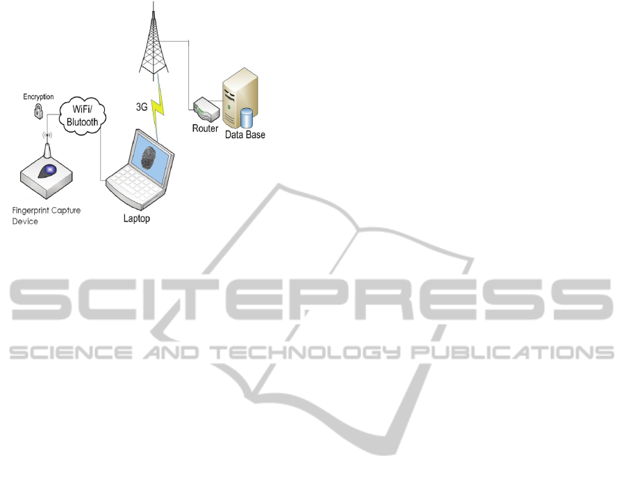
Figure 8: System diagram displaying the flow of data from
the mobile unit to a nearby supporting PC and then to a
remote database via a 3G cellular connection.
Li-ion polymer cells were chosen due to their high
energy density and low internal resistance. A robust
set of features protect and maintain these battery
cells. These include the use of high efficiency
switching regulators, selective power delivery, and
clock frequency switching on all onboard
processors. Individual battery cells are different due
to variances in manufacturing processes. In a multi-
cell battery pack each cell may have minor
differences in their discharge and charge profiles
resulting in each cell charging to slightly different
voltages. Cell balancing is used to keep the cells in
the battery system balanced and to maximize battery
longevity and capacity. This is done in the current
system in real-time and is controlled through
software on the PIC microcontroller. This system
also features low voltage, over voltage, over
discharge, and over charge protection. Idle power
consumption has been minimized to obtain longer
battery life. When in idol mode, both of the systems
processors clock frequencies are reduced in an effort
to minimize unnecessary power consumption.
Selective power management techniques, which
intelligently deliver power to each module in the
system as needed, are also utilized. In the current
design, each subsystem is severed from its power
source programmatically when it is not needed. For
instance, when the unit is idle, all of the circuitry
controlling the adaptive lighting, the motor, and the
camera systems are disconnected from system
power. This eliminates most of the idle power
consumed by devices while not in use. Through the
use of selective power delivery, the current system is
able to achieve over 150 hours of standby operation,
or over 1000 scans per charge.
3 CONCLUSIONS
The line-scan contactless fingerprinting system
described is compatible with AFIS and APIS. This
novel fingerprinting technology meets the
requirements of federal law enforcement regulations.
Our study has shown that a line-scan technique is a
suitable and high-resolution technique for
contactless and low-distortion acquisition of
fingerprints. In contrast to the contactless system
that uses six separate area cameras as described in
(Parziale, 2006), line-scanning allows for the
creation of high-resolution fingerprint capture
systems that are cheap, small, and portable
(Mil’shtein, 2008). The system described is expected
to be used in police patrol cars, border patrols,
access control environments, and in fingerprint data
processing centers. For mobile applications, the
system is equipped with a battery system that allows
for over 150 hours of standby operation, or over
1000 scans per charge. The system also contains a
WIFI module to facilitate wireless connectivity and
fingerprint transfers between the fingerprint reader
and a host computer. This system also acquires a
blood vessel map for use as a second method for
biometric identification. The automatic operation of
our fingerprint capture system is supported by
embedded software released under GPL, which will
allow any potential customer to purchase the system
without a need to license any external software
package. In the near future, we will be testing the
novel system with the police departments and the
police officers.
REFERENCES
Xia X., O’Gorman L., 2003. “Innovations in Fingerprint
Capture Devices” Pattern Recognition, 36, 2, pp: 361-
369.
Mil’shtein S., Doshi U., 2004. “Scanning of the pressure-
induced distortion of fingerprints” Scanning, 26, 4, pp:
323-327.
Palma J., Liessner C., and Mil’shtein S., 2006.
“Contactless Optical Scanning of Fingerprints with
180º View”, Scanning, 28, 2, 90.
Parziale G. and Diaz-Santana E., 2006. “The Surround
Imager: A Multi-Camera Touchless Device to Acquire
3D Rolled-Equivalent Fingerprints,” Prec. of Conf.
Int’l Conf. Biometrics, pp. 244-250.
S. Mil’shtein, J. Palma, C. Liessner, M. Baier, A. Pillai,
and A.Shendye, 2008. "Line Scanner for Biometric
Applications" IEEE Intern. Conf. on Technologies for
Homeland Security, ISBN 978-1-4244-1978-4 P 205-
208.
AUTOMATIC CONTACTLESS MOBILE FINGERPRINTING SYSTEM
449

S. Mil’shtein, M. Baier, C. Granz and P.Bustos, 2009.
"Mobile System for Fingerprinting and Mapping of
Blood -Vessels across a Finger", ISBN 978-1-4244-
4179-2, p.30-34.
Parziale G., Diaz-Santana E., 2006 “3D Touchless
Fingerprints: Compatibility with Legacy Rolled
Images” Proc. Int’l Conf. Biometrics, pp: 244-250.
Yi Chen, Geppy Parziale, Eva Diaz-Santana, and Anil K.
Jain, 2006. ‘3D Touchless Fingerprints: Compatibility
with Legacy Rolled Images’ 1 Michigan State
University, Department of Computer Science and
Engineering, East Lansing, Michigan, 48824, 2 TBS
Holding AG, Schindellegistrasse 19 CH-8808,
Pfaeffikon, Switzerland
Nixon K. A., Rowe R. K., 2005. “Multispectral
Fingerprint Imaging for Spoof Detection,” Proc. SPIE
Conf. Biometric Technology for Human Identification,
pp: 214-225.
Mitsubishi, 2006. “Mitsubishi Touchless Fingerprint
Sensor,” http://global.mitsubishielectric.com.
PECCS 2011 - International Conference on Pervasive and Embedded Computing and Communication Systems
450
