
REAL-TIME LOCALIZATION OF AN UNMANNED GROUND
VEHICLE USING A 360 DEGREE RANGE SENSOR
Soon-Yong Park and Sung-In Choi
School of Computer Science and Engineering, Kyungpook National University
1370 Sankyuk-dong, Puk-gu, Daegu, 702-701 Korea
Keywords:
Localization, 3D Sensor, Registration, Unmanned vehicle.
Abstract:
A computer vision technique for the localization of an unmanned ground vihicle (UGV) is presented. The pro-
posed technique is based on 3D registration of a sequence of 360 degree range data and a digital surface model
(DSM). 3D registration of a sequence of dense range data requires a large computation time. For real time
localization, we propose projection-based registration and uniform arc length sampling (UALS) techniques.
UALS reduces the number of 3D sample points while maintaining their uniformity over range data in terms
of ground sample distance. The projection-based registration technique reduces the time of 3D correspon-
dence search. Experimental results from two real navigation paths are shown to verify the performance of the
proposed method.
1 INTRODUCTION
Three dimensional (3D) registration is a computer vi-
sion technique to align multi-view range data with re-
spect to a common coordinate system. Many inves-
tigations have been introduced for 3D model recon-
struction, 3D robot vision, etc. Recently in robotics
community, 3D registration is applied to localization
of unmanned robots or vehicles from range data ac-
quired from 3D sensors.
A 3D sensor mounted on an unmanned vehicle
captures the 3D shape around the vehicle, which is
a local 3D map represented with respect to the sensor
coordinate system. If there is a global and reference
3D map which contains the 3D shape information of
navigation environment, the vehicle location can be
determined by matching the local map with respect to
the global map. By the way, an initial position of the
vehicle can be coarsely estimated by a GPS or INS
sensor. Therefore, it only needs to refine the initial
position to correctly match local and global 3D maps.
A common approach of 3D registration is using
the ICP algorithm (Besl and McKay., 1992). R. Mad-
havan et. al. (Madhavan et al., 2005) register a se-
quence of 3D range data in a pair-wise manner to de-
termine a robot pose. A modified ICP algorithm is
employed to cope with matching outliers. Triebel et.
al. (Triebel et al., 2006) introduce multi-level surface
maps to classify surface patches to several object cat-
egories. Levinson et. al. (Levinson et al., 2007) use a
digital map of urban environment. A particle filter is
used to match local range data to the map.
In a few investigations, 360 degree range sensors
are used to capture omnidirectional range data. Him-
melsbach et. al. (Himmelsbach et al., 2008) segment,
classify, and track 3D objects using a 360 degree laser
sensor. They generate occupancy grids from range
data to identify obstacles. K¨ummerle et. al. (Kum-
merle et al., 2009) present an autonomous driving
technique of an unmanned vehicle which is equipped
with multiple navigation sensors including a 360 de-
gree range sensor. In our previous work, a 3D reg-
istration technique is introduced to align 360 degree
range data and a digital surface model (DSM)(Park
and Choi, 2009).
Matching 3D maps obtained from different coor-
dinate systems requires a reasonable number of cor-
respondences between the maps (Hartley and Zisser-
man, 2000). Since a 360 degree range sensor cap-
tures a huge number of 3D points, it requires a sig-
nificant time for 3D registration. For real-time lo-
calization of an unmanned ground vehicle (UGV),
we introduce projection-based registration and uni-
form ground distance sampling techniques to reduce
the number of correspondence. Experimental results
show that the proposed method can find robot position
in about 15Hz rate.
610
Park S. and Choi S..
REAL-TIME LOCALIZATION OF AN UNMANNED GROUND VEHICLE USING A 360 DEGREE RANGE SENSOR.
DOI: 10.5220/0003362406100613
In Proceedings of the International Conference on Computer Vision Theory and Applications (VISAPP-2011), pages 610-613
ISBN: 978-989-8425-47-8
Copyright
c
2011 SCITEPRESS (Science and Technology Publications, Lda.)

2 RANGE FORMAT & SAMPLING
2.1 Range Data Format
The range sensor used in this paper is a Velodyne
HDL-64ES2 LADAR sensor mounted on the top of
an UGV. The sensor captures 360 degree range data
by rotating 64 lasers and detectors at 10Hz revolution
rate. The sensor is mounted at 2.081m height from
the ground. The vertical field of view of the sensor
is 26.8 degree, 2 degree above and 24.2 degree below
the horizontal plane.
Each laser detector captures maximum 2048 3D
points in a single revolution. Total 64 laser detectors
then capture 3D point clouds which are represented
with respect to the sensor coordinate system as shown
in Figure 1. To rasterize the 3-D data, we convert
the point clouds to a 2.5D depth map called “range
frame”. The size of the map is 64× 1800 in row and
column, where the row index L and the column index
φ correspond to the laser number and the horizontal
angle, respectively. As the column index, 360 degree
range data is quantized with 0.2 degree angular reso-
lution.
Figure 1: Format of 360 degree range frame.
2.2 Uniform Arc Length Sampling
In this section, we propose a new sampling method
called a uniform arc length sampling (UALS) tech-
nique. In contrast to conventional uniform point sam-
pling (UPS) techniques, our approach uniformly sam-
ples 3D points in terms of ground distance along the
scan circles. Let α(L) be the circumference of a scan-
ning circle of a line L, and θ(L) be a vertical an-
gle between the horizontal plane and a ray from the
sensor to line L. Then α(L) is proportional to the
tan(90− θ(L)).
If θ(L) is larger than 1.0 degree, α(L) is com-
puted as shown in Equation 1. In this equation, h is
the height of the sensor from the ground, d
max
is the
maximum sensing distance, and α
max
is the maximum
circumference. The sampling interval φ
s
(L) along the
rotation angle is then computed by dividing the max-
imum sensing circumference by α(L) as in Equation
2.
α(L) =
α
max
= 2πd
max
if θ > 1.0,
2πh× tan(90− θ(L)) otherwise.
(1)
φ
s
(L) = ⌊
kα
max
α(L)
+ 0.5⌋ (2)
In each scanning line of a range frame, we sam-
ple 3D points from the first point P(0, L) to the i-th
sample point such that
P
i
(L) = P(i× φ
s
(L), L). (3)
As shown in the right of Figure 2, sampling is done
with uniform arc length kα
max
regardless of scanning
distance of each line. Here, k is a constant to con-
trol the density of sampled points. However, in con-
ventional UPS method, φ
s
(L) is constant. Depending
on the value of φ
s
(L), the sampling density could be
too dense or sparse in UPS method. On the contrary,
UALS method samples 3D points uniformly over all
scanning lines in terms of ground sample distance.
Figure 2: Comparison of two sampling methods, UPS and
UALS.
3 AUTOMATIC LOCALIZATION
3.1 Localization Scheme
Localization of an UGV is done by two separate regis-
tration steps as shown in Figure 3. A pairwise (local)
registration step is followed by a (global) registration
step. The local registration aligns two consecutive
range frames and computes the transformation of the
current range frame with respect to an initial position.
However, accumulation errors due to the registration
of a long sequence of range data could yield erroneous
localization. To overcome this problem, a global reg-
istration is done next (Park and Choi, 2009).
Figure 3: Flow of autonomous localization.
3.2 Projection-based ICP
In pair-wise registration, it is required to find corre-
REAL-TIME LOCALIZATION OF AN UNMANNED GROUND VEHICLE USING A 360 DEGREE RANGE SENSOR
611
spondences between two 3D range frames, source and
destination as shown in Figure 4. Suppose there is a
3D point P in the source frame. Then, we need to find
a matching point Q
′
in the destination. A projection-
based registration is introduced for fast correspon-
dence search.
Suppose the source is the current frame (n) and
the destination is the previous frame (n-1). The pre-
vious frame is considered to be aligned already with
respect to a reference coordinate sytem. Let the cur-
rent position of the source frame be the same with that
of the destination, which is T
n−1,0
. To find the corre-
spondence, we first transform the source point P to
the initial position such that P
′
= T
−1
n−1,0
P. Second,
P
′
is projected to a 2D point q(φ, L) in the destina-
tion frame by calculating φ and L. Then, we search Q
which is the closest to P. Since two range frames are
reasonably close enough, we can restrict the search
range as shown in the figure. In real experiments, we
fix the angle search range to ±15
◦
and the line range
to ±3 from q(φ, L).
The corresponding point Q
′
is now derived as the
intersection of the normal vector of P with the tangent
plane at Q. After a sufficient number of correspon-
dences are defined, a transformation matrix T
pair
=
[R
pair
|t
pair
] can be derived to minimizes the registra-
tion error ε
pair
as in Equation 4.
ε
pair
=
K
∑
k=1
kQ
′
k
− (R
pair
P
k
+ t
pair
)k
2
. (4)
After the pair-wise registration is finished, the posi-
tion of the current frame is refined using a digital sur-
face model. An ICP-based method is used in the sec-
ond step. However, the DSM is divided into multi-
ple elevation layers to speed up the global registration
(Park and Choi, 2009).
Figure 4: Projection-based pairwise registration scheme.
4 EXPERIMENTAL RESULTS
To analyze the localization error of the proposed
method, two different navigation paths are used.
Along each navigation path, we drive an outdoor
UGV and acquire a sequence of 3D range data. At the
same time, we record the ground truth positions of the
path in every revolution of the 360 degree range sen-
sor. The sensor is rotated in 10Hz revolution speed.
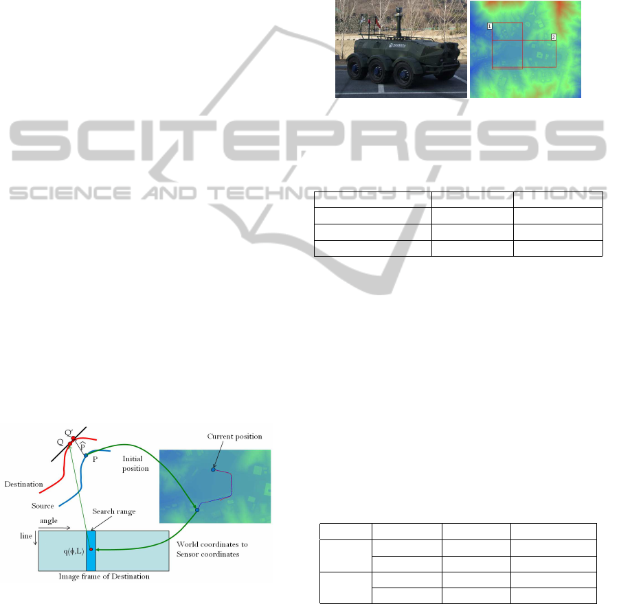
The UGV used in this experiment is shown in Figure
5(a). A DSM with two navigation regions is shown
in Figure 5(b). Table 1 shows some properties of two
navigation paths.
(a) (b)
Figure 5: (a) An UGV with 360 degree range sensor (b)
DSM.
Table 1: Properties of navigation paths.
Path Path-1 Path-2
# of frames 650 970
DSM size(pixel) 969×2713 1677×1441
DSM accuracy (m) 0.5 0.5
We compare our localization method with an ICP
algorithm. In this ICP algorithm, source points are
sampled by UPS and the k-d tree search algorithm is
also combined when searching the closest points. In
each navigation path, average registration error and
processing time are recorded. For fair comparison,
the number of sampled points of two methods are set
as same as possible.
Table 2 shows the results of two paths. In both
paths, localization time of our method is less than
0.1sec, which means more than 10Hz speed. Local-
ization speed is about three times faster than the ICP
method. Localization error is also smaller than the
ICP.
Table 2: Average localization error and time.
Path Method Error (m) Time (msec)
Path-1 ICP+UPS 6.5 273.9
Proposed 4.63 92.4
Path-2 ICP+UPS 7.27 365.3
Proposed 4.46 97.3
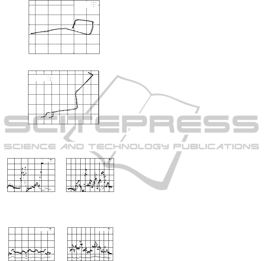
Figure 6 plots the vehicle positions of two experi-
ments with respect to the ground truth. In each figure,
our method is compared with the ICP method. Plots
of our method are closer to the ground truth. Figure
7 shows localization error in each frame of the test
sequences. Compare to the ICP method, our method
VISAPP 2011 - International Conference on Computer Vision Theory and Applications
612
3930900
3931000
3931100
3931200
3931300
3931400
449300 449400 449500 449600 449700 449800
Y (m)
X (m)
Groundtruth
ICP_UPS
Proposed
(a)
3931000
3931100
3931200
3931300
3931400
3931500
449150 449200 449250 449300 449350 449400 449450 449500 449550 449600
Y (m)
X (m)
Groundtruth
ICP_UPS
Proposed
(b)
Figure 6: Localization path comparison (a)Path-1 (b)Path-
2.
0
5
10
15
20
25
30
0 100 200 300 400 500 600 700
Position error (m)
Frames
ICP+UPS
Proposed
(a)
0
5
10
15
20
25
30
0 100 200 300 400 500 600 700 800 900 1000
Position error (m)
Frames
ICP+UPS
Proposed
(b)
Figure 7: Localization error in the test sequences (a)Path-1
(b)Path-2.
0
200
400
600
800
1000
0 100 200 300 400 500 600 700
Registration time (msec)
Frames
ICP+UPS
Proposed
(a)
0
200
400
600
800
1000
0 100 200 300 400 500 600 700 800 900 1000
Registration time (msec)
Frames
ICP+UPS
Proposed
(b)
Figure 8: Localization time in the test sequences (a)path-1
(b)path-2.
yields smaller localization error through all frames.
Figure 8 compares localization time of two methods.
There shows high variance in the ICP method, which
means unstable localization. On the contrary, local-
ization of our method is very fast and stable.
5 CONCLUSIONS
Real time localization of an unmanned ground vehi-
cle is introduced. A pairwise registration of 360 de-
gree range data is implemented through a projection-
based iterative alignment. Without searching match-
ing points in 3-D space, the projection-based method
can find correspondences in very fast time. To reduce
the number of matching pairs as small as possible,
a uniform arc length sampling method is also pro-
posed. Using the proposed sampling method, match-
ing pairs are uniformly distributed in terms of ground
distance between samples. Experiments are done us-
ing sequences of 3D range data obtained from two
navigation paths. In terms of speed and accuracy, the
proposed method yield better performancethan a con-
ventional method.
ACKNOWLEDGEMENTS
The Authors gratefully acknowledge the supports
in part from UTRC(Unmanned technology Research
Center) at KAIST, originally funded by DAPA, ADD
and MKE under the Core Technology Development
for Breakthrough of Robot Vision Research support
programsupervised by the NIPA (NIPA-2010-C7000-
1001-0006).
REFERENCES
Besl, P. J. and McKay., N. D. (1992). A method for regis-
tration of 3-d shapes. IEEE Trans. on Pattern Recog-
nition and Machine Intelligence, 14(2):239–256.
Hartley, R. I. and Zisserman, A. (2000). Multiple View Ge-
ometry in Computer Vision. Cambridge University
Press.
Himmelsbach, M., Muller, A., Luttel, T., and Wunsche, H.
(2008). Lidar- based 3d object perception. In Proc.
of the 1st Int’l Workshop on Cognition for Technical
Systems.
Kummerle, R., Hahnel, D., Dolgov, D., Thrun, S., and Bur-
gard, W. (2009). Autonomous driving in a multi-level
parking structure. In Proc. of the IEEE Int’l Conf. on
Robotics and Automation.
Levinson, J., Montemerlo, M., and Thrun, S. (2007). Map-
based precision vehicle localization in urban environ-
ments. In Proc. of Robotics: Science and Systems.
Madhavan, R., Hong, T., and Messina, E. (2005). Tempo-
ral range registration for unmanned ground and aerial
vehicles. Journal of Intelligent and Robotic Systems,
44(1):47–69.
Park, S. and Choi, S. I. (2009). Localization of an un-
manned ground vehicle using 3d registration of laser
range data and dsm. In Workshop of Applications of
Computer Vision.
Triebel, R., Pfaff, P., and Burgard, W. (2006). Multi-level
surface maps for outdoor terrain mapping and loop
closing. In Int’l Conf. on Intelligence Robotics and
Systems(IROS), pages 2276–2282.
REAL-TIME LOCALIZATION OF AN UNMANNED GROUND VEHICLE USING A 360 DEGREE RANGE SENSOR
613
