
FLEXIBLE CLIPMAPS FOR MANAGING GROWING TEXTURES
Dirk Feldmann, Frank Steinicke and Klaus H. Hinrichs
Visualization and Computer Graphics Research Group, University of M
¨
unster, Einsteinstr. 62, 48149 M
¨
unster, Germany
Keywords:
Computer graphics, Real-time rendering, Texture generation, Texturing, clipmap, Growing texture.
Abstract:
Previous work on large image data sets has evolved techniques for handling representations of these data
that cache textures of arbitrary, but fixed, size in a limited amount of physical memory for rendering in real-
time. In these approaches the texture data is usually pre-processed and arranged, for instance in a geometry-
independent texture clipmap. New technologies in the area of remote sensing generate aerial images in real-
time at a high rate in a patchwork-like pattern, and new images may replace previously captured image data.
These patchwork-like image data can be used to create a growing texture which is dynamic in the sense that
it may be updated in parts and grow in extension in the course of time. For such growing textures, current
clipmap techniques are not appropriate.
In this paper we introduce the Flexible Clipmap, a technique for incrementally generating a clipmap from a
large virtual texture of dynamically changing content and extent. Our technique makes use of a tile-based
clipmap approach and a common spatial indexing data structure to provide access to very large growing tex-
tures. We present an evaluation of our technique in the context of a remote sensing application which demands
real-time rendering of growing texture data.
1 INTRODUCTION
With the widespread use of applications like Google
Earth/Maps or GIS, textures depicting large surface
areas or even entire planets have become rather pop-
ular. The texture data in these applications may
have sizes in the gigabyte range and thus often ex-
ceed the available physical video memory. For this
reason different techniques for handling very large
textures have been developed. However, in many
of these applications textures are frequently treated
as resources having fixed extent and static or rarely
changing content. While these constraints have ap-
plied until recently, advances in image acquisition
techniques makes it now possible to update such im-
age data more frequently and at lower costs. The
acquired images need to be processed to generate a
single virtual texture which can be used for render-
ings of a digital model of the captured environment.
Although the covered areas may be vast and the im-
ages may have high resolution, it is desirable to up-
date the content of such a very large virtual texture
in real time. Furthermore, any newly acquired im-
age may not only update existing content, but also
extend the area covered so far. In this case, the vir-
tual texture may extend in size, hence we refer to
such a kind of texture as a growing texture. Appli-
cations can be found in monitoring in-process image
acquisition, as it is done, for example, in microscopy,
robotics or aerial photography for purposes of survey-
ing and mapping. For instance, miniature unmanned
aerial vehicles (MUAVs) equipped with cameras can
capture image data about arbitrary areas and transfer
these images using advanced network technology to
ground control stations where the data can be dis-
played immediately (AVIGLE, 2010). Current tech-
niques for handling large textures, like clipmap im-
plementations, are not able to handle such growing
textures.
In this paper we present the Flexible Clipmap
(FCM) to incrementally generate a large, virtual tex-
ture of dynamically changing content and growing ex-
tent. Our technique makes use of a tile-based clipmap
approach, a common spatial indexing data structure
and commodity GPUs, and is independent of the un-
derlying geometry data.
2 RELATED WORK
If the size of textures to be displayed exceeds the
hardware limits, a common and obvious solution is
to divide them into smaller, manageable textures. For
173
Feldmann D., Steinicke F. and H. Hinrichs K..
FLEXIBLE CLIPMAPS FOR MANAGING GROWING TEXTURES.
DOI: 10.5220/0003363701730180
In Proceedings of the International Conference on Computer Graphics Theory and Applications (GRAPP-2011), pages 173-180
ISBN: 978-989-8425-45-4
Copyright
c
2011 SCITEPRESS (Science and Technology Publications, Lda.)

instance, Cline and Egbert proposed a simple divi-
sion of the texture data, but their approach was lim-
ited by a strict dependency on texture coordinates and
underlying geometry (Cline and Egbert, 1998). A
clipmap, as introduced in (Tanner et al., 1998), is
based on mipmaps (Williams, 1983) and keeps only
portions of the entire texture mipmap in video mem-
ory. Like mipmaps, the clipmap provides a level of
detail (LOD) concept and thus avoids texture alias-
ing. It uses a roaming window in video memory to
copy only those texels which are visible to the viewer
by logically centering the window around the cur-
rent eye point (clip center). As the eye point moves,
the window is updated by copying new texels using
toroidal addressing (Tanner et al., 1998). This is done
for each clipmap level corresponding to a texture of
a size greater than a certain clip size. Lower levels
are treated as an ordinary mipmap. No subdivision
of a large texture into so-called tiles is required, but
special hardware was employed for loading the texels
into video memory. Modern GPU features have elim-
inated the need for special hardware, and the clipmap
concept has been implemented on the GPU in vertex
and fragment shaders on commodity hardware mak-
ing it even more attractive for handling large textures.
The virtual texture in (Ephanov and Coleman, 2006)
also makes use of texture tiles and can employ shaders
for texture mapping. It supports multi-texturing, but
does not use toroidal addressing for loading tiles, the
texture coordinates are still coupled to the geome-
try and it requires multiple texturing units, even if
only a single texture is mapped. In (Seoane et al.,
2007) a roaming tile cache for each level is used,
which is updated using toroidal addressing and tex-
ture stacks. Geometry and texture data are kept in-
dependent from each other by computing the texture
coordinates within a shader. Both approaches as well
as the solution presented in (Li et al., 2009) generate
complete mipmaps for each tile at each LOD. Craw-
fis et al. (Crawfis et al., 2007) also employ roaming
tile caches for each level, toroidal addressing, texture
compression and fragment programs, but they do not
generate mipmaps for the tiles. They investigate dif-
ferent methods for clipping and level determination
by utilizing fragment programs and arrays of textures
to hold the relevant portions of the logical mipmap.
Furthermore, they make use of a tile map to indicate
the highest available texture resolution for each pixel
to the shader for selecting the optimal clip level by
binding the tile map as an additional texture. In addi-
tion, they propose the usage of more efficient texture
arrays, which became available in DirectX 10 hard-
ware. Recently, also (Barrett, 2008) and (Mittring
and Crytek GmbH, 2008) have used virtual textures
on modern GPUs.
Although the previously mentioned works on tex-
ture clipmaps deal with large textures of fixed extent,
they do not seem to be capable to update the texture
content at a frequent rate. Recently, in (Taibo et al.,
2009) a method to handle large fixed-size textures
of frequently changing content has been presented.
However, to our knowledge none of the current tech-
niques is able to handle growing textures.
3 THE FLEXIBLE CLIPMAP
The FCM allows to derive from a growing set of
images at different locations a single virtual texture
which can be rendered immediately on any geometric
model. This is only possible if along with the im-
ages the information about their location in the real
world is provided. Before images can contribute to
the virtual texture, georeferencing and registration of
the images have to be performed, and, if necessary,
perspective distortions need to be reduced. In aerial
imaging applications, georeferencing of the images is
realized based on position and orientation data which
may be provided by GPS and inertial measurement
units. After this preprocessing the area covered by an
image does not need to be rectangular any more, but
is an arbitrary convex quadrilateral. However, a min-
imal enclosing axis-aligned rectangle (bounding box)
can be computed efficiently. The undistorted image
together with its bounding box and some meta infor-
mation like position data, time stamp, image contrast,
etc. is called a patch.
3.1 Requirements and Contributions
In order to handle a growing texture, the FCM can-
not be confined in advance to a fixed area. Also it
may easily become too large to fit entirely into video
memory or even main memory and therefore it has to
be partitioned, stored in secondary memory and pro-
vided with a LOD concept to avoid texture aliasing.
Furthermore, for a frequently changing set of images
overlapping the same area, there are lots of possibil-
ities to decide which of the images (or parts of the
images) are the “best” to contribute to the resulting
virtual texture. A rating can be based, for instance, on
image properties such as timestamp, contrast, bright-
ness, signal-to-noise ratio, degree of perspective dis-
tortion, or even content. In any case, whenever “bet-
ter” images are available, the affected region within
the virtual texture has to be updated. To summarize,
the FCM must satisfy the following requirements to
address the challenges stated above:
GRAPP 2011 - International Conference on Computer Graphics Theory and Applications
174
1. Partitioning and LOD concepts have to be sup-
ported, since the virtual texture may have physical
extent which exceeds hardware limits.
2. Efficient updates of the virtual texture must be
possible, because updates of the underlying set of
images will occur frequently.
3. The virtual texture must be capable of growing,
i. e., it cannot be limited to a fixed extent.
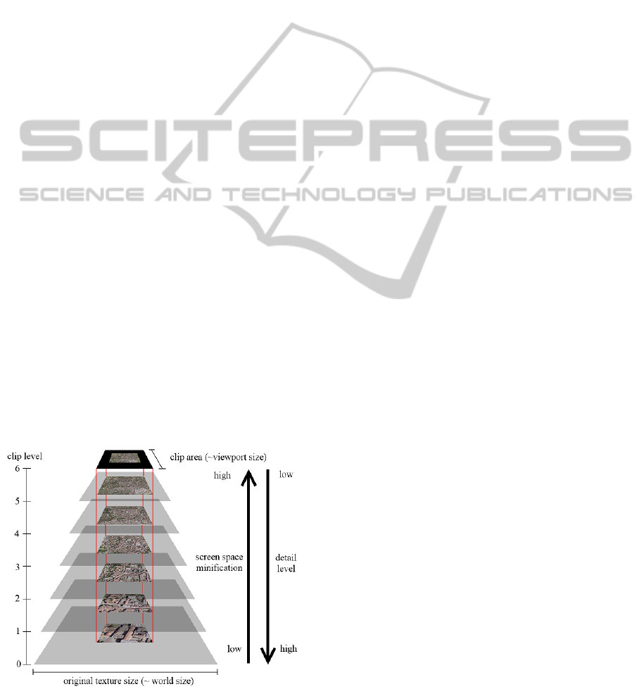
3.2 Clipmap
The first requirement given in Section 3.1 can be
achieved with texture clipmaps, since they allow to
control memory consumption and provide LOD con-
cepts. The principle of a clipmap is illustrated in
Figure 1. At the lowest clip level l = 0 the clipmap
(cf. (Tanner et al., 1998)) contains a portion of the
texture at the highest available resolution. Like with
mipmaps, going from clip level l to clip level l + 1
the resolution of the texture decreases by a factor of
2 along each dimension. At the highest clip level
L − 1, the clipmap contains a down-sampled version
of the entire texture, which is managed like a standard
mipmap. During texture mapping the minification of
a texel in screen space determines the clip level to be
used. We implemented a variation of the clipmap sim-
ilar to the one in (Crawfis et al., 2007) which makes
use of fragment shaders and texture tiles without re-
quiring any special hardware. We employ a tile map
as well and make use of the explicit index-based clip-
ping (Crawfis et al., 2007), but in contrast, we use a
special approach for indexing and generating the re-
quired texture tiles. Because of the tiling approach,
updates of the virtual texture are confined to few tiles
only, which is helpful for achieving the second re-
quirement stated in Section 3.1.
Figure 1: Scheme of a clipmap with L = 7 clip levels.
3.3 Patch Organization
In our application, the texel source for each tile is
the set of patches the tile overlaps. To satisfy the
second requirement from Section 3.1, we need to
be able to efficiently retrieve the patches contribut-
ing to a certain tile. For this reason, the patches
are stored in a spatial indexing data structure accord-
ing to their bounding boxes in real-world coordinates
(RWC). Since the spatial index has to support point
and especially window queries, we employ the R
∗
-
tree (Beckmann et al., 1990), a variation of the R-tree
(Guttman, 1984). Compared to other spatial index-
ing structures, the R
∗
-tree has the advantage that it
can be used as a secondary storage index, and that
it is well suited for incremental construction by suc-
cessive insertions as it does not require any periodic
re-organizations (Samet, 2006).
Since the R
∗
-tree stores in each node a bounding
box of all elements assigned to the corresponding sub-
tree, the bounding box for all patches is located and
maintained at the root node. This bounding box given
in RWC together with a given image resolution in pix-
els per RWC unit determine the current size of the
FCM. Therefore the extent of the FCM will change
when patches are inserted which do not lie completely
within its current boundaries (cf. Section 3.5).
Given the bounding box of a certain tile in RWC,
in order to update that tile the spatial index is queried
using the bounding box, and the retrieved patches are
blended into the texture tile (see Section 3.6).
3.4 Flexible Tiles Construction
In order to satisfy the third requirement from Sec-
tion 3.1, the key is to provide the FCM with additional
tiles whenever the underlying virtual texture becomes
larger. We start numbering the L clip levels of the
FCM from the most detailed level l = 0 to the least
detailed level l = L − 1, which contains a downsam-
pled version of the entire texture (see Figure 1). Con-
ceptually, we consider the virtual texture as the entire
R
2
. We denote the space covered by the bounding
box of the R
∗
-tree by A, its left lower and right upper
corners by ll and ru, respectively, and we mark the
region R
2
\A as empty.
We take an arbitrary but fixed origin o = (o
x
,o
y
)
in RWC, e. g., the starting location of the exploration
or any GPS position, to span a Cartesian grid with
spacing (g
x
,g
y
) = (t
x
/ppu
x
,t
y
/ppu
y
) in x- respec-
tively y-direction, where t
x
and t
y
denote the width
respectively height of one tile in texels, and ppu
x
and
ppu
y
denote the resolution in the respective direction
in pixels per units. Each grid cell is identified with
FLEXIBLE CLIPMAPS FOR MANAGING GROWING TEXTURES
175
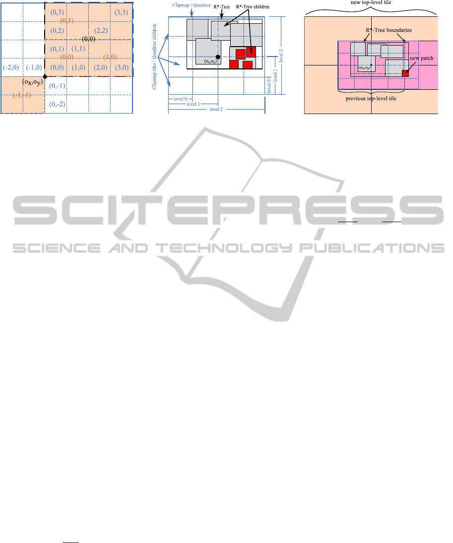
(a) indexing tiles within the FCM (b) relation of R
∗
-tree and quadtree (c) expansion of the FCM
Figure 2: Overview of the most important concepts used for constructing the Flexible Clipmap.
exactly one texture tile at level l = 0 and indexed as
shown in Figure 2(a). Starting with l = 0 at the ori-
gin, 2 ×2 neighbored grid cells at level l are grouped
to a cell of size 2
l+1
· g
x
× 2
l+1
· g
y
, and thus concep-
tually a quadtree is specified. This process is repeated
until A is covered in x- or y-direction by at most two
grid cells each, but by at least two in one of the direc-
tions. The tiles from higher levels 0 < l < (L −1) are
obtained by identifying each tile either with the corre-
sponding quadtree node at the same level or with the
area covered by the equivalent grid cell in RWC. Like
with mipmaps, the content of each tile is determined
by the content of its children, but the position of each
tile in RWC is fixed.
The top-most tile at level L −1 requires some spe-
cial attention, because as a constraint for the FCM,
this level must cover A entirely while consisting of
exactly 2 × 2 subordinated tiles (children). In cases
of having only 1 × 2 or 2 × 1 children, the miss-
ing ones are replaced by the nearest, even empty,
neighbors in the corresponding direction. If the top-
level tile would be constructed from the quadtree as
well, the quadtree root might be located at a level
≥ L and many empty children would have to be in-
cluded to satisfy this constraint. Besides, the top-level
tile is indexed (0,0), because its quadtree node may
not necessarily be the parent node of all of its chil-
dren any longer, e. g., if it was formed by the nodes
((1,−1),(2,−1),(1,0),(2,0)) at L − 1.
Given a certain level, we can determine the tile
index n(l, r) = (n
x
,n
y
) to which a location r = (r
x
,r
y
)
in RWC belongs by the following relation:
n(l,r)
d
=
(
j
r
d
2
l
·g
d
k
0 ≤ l < (L −1)
0 l = (L − 1)
, d ∈
{
x,y
}
Since L depends on the position of ll and ru at the top
level L − 1, the total number of clip levels L cannot be
determined by the following quantity:
ˆ
L = max
d∈
{
x,y
}
(
d
log
2
(ru
d
− ll
d
)
e
−
d
log
2
(g
d
)
e
)
According to the description above, L − 2 is the level
l
0
where at least one of the two components of the dif-
ference of the tile indices n(l
0
,ru) and n(l
0
,ll) equals
one. This is expressed in the following equation:
n(l
0
,ru)
d
− n(l
0
,ll)
d
=
ru
d
2
l
0
g
d
−
ll
d
2
l
0
g
d
!
= 1 (1)
We actually determine the required number of clip
levels L by checking if l
0
=
ˆ
L satisfies Equation 1. If
it does not, l
0
is incremented and checked again, until
a suitable l
0
is found.
Most important about this indexing is that n(l,r)
does not directly depend on A. This facilitates adding
new tiles to the FCM, because each tile at each level
has a unique index and conceptually already exists,
though it may not contain image information. The re-
lation of the R
∗
-tree, A and the quadtree is illustrated
in Figure 2(b).
3.5 Expanding Textures
An expansion of A into any direction is triggered by
the insertion of new patches which are not completely
covered by A. This leads to the addition of at least
one new clip level if A then exceeds the boundaries
of the current top-most tile at L − 1 as illustrated in
Figure 2(c). The total number of new clip levels de-
pends on the extension of A. In that case, the former
tile at level L − 1 does no longer satisfy the constraint
of covering at most 2 × 2 tiles from the next lower
level, and the maximum clip level has to be increased
by the number of new levels k, so we denote the for-
mer number of clip levels by L
0
and set L = L
0
+ k.
All other tiles remain unchanged with respect to their
indices, with the exception of the former top-level tile
at L
0
− 1, because its index (0,0) does not necessar-
ily reflect the indices of subordinated tiles any longer.
The entire tile is therefore discarded and then recre-
ated from its 2 × 2 children, which will have been up-
dated by then (see Section 3.6).
GRAPP 2011 - International Conference on Computer Graphics Theory and Applications
176
3.6 Updating Tiles
In principle, tiles need to be updated as soon as they
are covered by a new patch, but depending on the
application, it may be sufficient to start updating af-
fected tiles only if a certain threshold for the number
of new patches has been reached or after a certain pe-
riod of time. The spatial index supports easy access
to all patches that contribute to a certain tile (see Sec-
tion 3.3). The number of contributing patches may
increase over time as well as the costs for updating
one tile. Therefore, different selection criteria can be
applied to discard patches which are not to contribute
to the final texture, e. g., if the contrast of the image is
below a certain threshold or if it is outdated. Depend-
ing on the desired quality of the resulting virtual tex-
ture and the application, it may be sufficient to update
existing tiles incrementally by processing only the lat-
est patches and blend them with the previously gen-
erated tiles. Independent of whether tiles are updated
incrementally or extensively, we only update the tiles
at level l = 0 from patches. The patches themselves
are moved to secondary memory afterwards in order
to free main memory. Tiles at l > 0 (parents) will be
updated in increasing level order by recursively copy-
ing and scaling the respective regions covered by the
tiles at l −1. Therefore we keep the most recently up-
dated children from the current level in main memory
until their parents have been updated. Afterwards, the
parents take the role of their children, and the process
is repeated until the top-most tile has been updated.
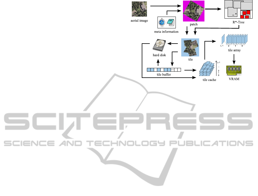
3.7 Architecture
One characteristic of clipmaps is the employment of
caching and secondary storage. In the FCM, we also
use a tile cache for caching an amount of c
x
(l) × c
y
(l)
texture tiles at each clip level l in main memory. As
described in (Tanner et al., 1998), the set is chosen
based on the current clip center with the c
x
(l) × c
y
(l)
neighbored tiles centered around it, and the set is
identical to the clip stack. Its content is updated as
the eye point moves by a distance greater than some
threshold, and the cache is accessed using toroidal
indexing on the tile indices. A smaller subset of
a
x
(l) × a
y
(l) tiles with a
d
(l) ≤ c
d
(l) and d ∈ {x, y},
which are also centered around the clip center and
visible to the viewer (active area), is copied to the tile
array in VRAM, which is realized as a texture array,
accessible by GPU shaders. The quantities c
d
(l) and
a
d
(l) depend on the clip level, but are limited by some
constants C
d
and A
d
defined by the user or the applica-
tion. However, A
d
must be chosen so that a
d
(0) times
the width respectively height of one tile in texels is at
Figure 3: Overview of the architecture of the FCM.
least as large as the width respectively height of the
application’s viewport in pixels in order to avoid visi-
ble borders of lower resolution during rendering.
Following the idea in (Crawfis et al., 2007), we
use an extra texture, the tile map, which is a down-
scaled version of the entire virtual texture and con-
tains at every texel the highest currently available clip
level of a tile in the tile array. The position of a tile
map texel is determined by the position (i. e., index) of
the corresponding tile and its level. The lateral dimen-
sions of the tile map tm
x
, tm
y
must satisfy Equation 2,
so that each tile at level 0 is represented by at least
one texel in the tile map, with L denoting the number
of clip levels.
log
2
min
d∈
{
x,y
}
{
tm
d
}
≥ (L − 1) (2)
To reduce storing and reloading tiles from sec-
ondary memory, we additionally keep a certain
amount b of the tiles which were not already cached
but have been loaded during updating in a tile buffer
in main memory. This is done because the viewer is
frequently tracking the regions which were recently
updated, and the affected tiles will likely be needed to
update the tile array in VRAM as well. Figure 3 con-
tains a sketch of the components and entities involved
in the FCM.
Whenever possible, reading from and writing to
secondary memory is done in a separate thread in or-
der to not stall the rendering and updating processes.
3.8 Rendering
Texture mapping using the FCM is implemented by
GPU fragment programs. The tile array and tile map
have to be bound to one texturing unit each and are
accessed by the shader. The texture coordinates (u,v)
are assumed to be in [0.0,1.0]
2
and have to map the
FLEXIBLE CLIPMAPS FOR MANAGING GROWING TEXTURES
177
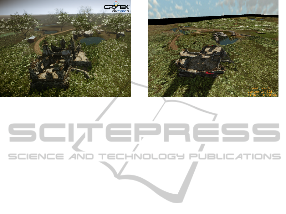
(a) simulated environment using CryEngine 3 (b) captured environment using FCM
Figure 4: Screenshots from the simulated environment and the captured environment. Black areas near the horizon in (b) have
not been captured so far.
entire R
2
, but the fragment shader transforms the co-
ordinates so that only the area covered by A is affected
by texture mapping from the FCM. For each fragment
the fragment program performs a look-up in the tile
map to determine the tile with the highest LOD l
max
available in the tile array and calculates an ideal level
l
ideal
(analog to (Crawfis et al., 2007)). The calcula-
tion of the ideal level is based on the texel minification
in screen space and uses a simplified anisotropic filter-
ing method by Ewins et al. (Ewins et al., 1998). The
final LOD l
f
is determined as l
f
= max (l
max
,l
ideal
).
If a tile could not be uploaded on time, the tile map
would contain the level of the next coarser LOD avail-
able; in the worst case, at least the top-level at L − 1
would be present.
4 PERFORMANCE ANALYSIS
The proposed FCM has been developed and analyzed
in the context of the AVIGLE project. One goal of
this project is to capture low-altitude aerial images
by a swarm of MUAVs, transfer these images to a
ground mission control station, and display them im-
mediately. The realization of this project requires
the development of a novel type of MUAV, advanced
swarm algorithms, network technology, and in par-
ticular fast and accurate image processing and visu-
alization strategies. For that reason, we have devel-
oped a simulation framework (Strothoff et al., 2010),
which allows to generate virtual aerial images at cus-
tom locations, orientations, resolutions and frequen-
cies from renderings of digital 3D models using any
visualization library or computer game engine like
the CryEngine (Crytek GmbH, 2010). The images
with added meta information are sent by a separate
thread over a network via TCP to a client application
where they are processed by the employed FCM. Fig-
ure 4 shows a screenshot of the simulated 3D envi-
ronment (left) and a screenshot of the client applica-
tion, depicting the corresponding area textured with
the content from the FCM which has been derived
from the virtual aerial images captured by a virtual
MUAV (right).
4.1 Evaluation Setup
The run-time performance of the rendering and the vi-
sual quality of the resulting texture map in the FCM
depend on the following quantities: the resolution of
the incoming patches in texels (p
x
, p
y
), the number of
patches per second (patch rate), the number of tile
updates per second (update rate), the resolution of
the final texture in pixels per unit (ppu), the resolu-
tion of tiles in texels (t
x
,t
y
) and the sizes of the tile
cache (c
x
(l),c
y
(l)), the tile buffer b and the active
area (a
x
(l),a
y
(l)) in number of tiles at each level l.
We analyzed the performance of the FCM in terms of
the number of updated tiles per second during con-
tinuous insertion of patches, because high rates of tile
updates are essential for growing and dynamically ad-
justing the content of the virtual texture.
In our evaluation setup, we always used a view-
port/screen size of (s
x
,s
y
) = (1024, 768) pixels,
ppu = 20, A
d
= ds
d
/t
d
e, C
d
= 2 · A
d
with d ∈
{
x,y
}
and b = C
x
·C
y
. For each tested configuration of tile
sizes, patch sizes and average patch rates, we sim-
ulated a single virtual MUAV equipped with a non-
metric camera and following exactly the same path
at a constant altitude of 50 m above sea level, and
we performed 10 runs each to obtain means. Means
are necessary, because the patches received by the
GRAPP 2011 - International Conference on Computer Graphics Theory and Applications
178
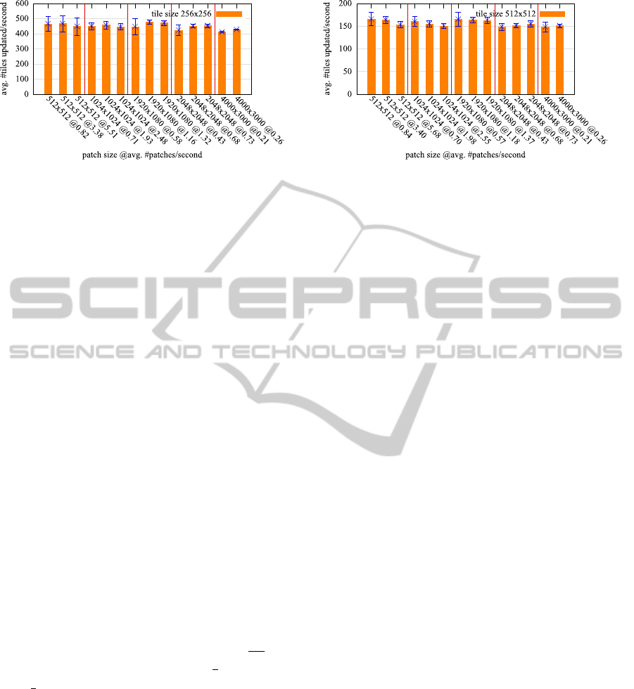
(a) tile size 256 × 256 texels (b) tile size 512 × 512 texels
Figure 5: FCM performance in terms of tile updates/second in our evaluation setup.
client are located at random positions along the path
of the virtual MUAV during different runs, as there
is no synchronization between the applications. In
addition, the simulator cannot guarantee to provide
a certain patch rate, which also strongly depends on
the resolution of the patches and the network. Tile
updates were performed in every frame whenever at
least one new patch was received. The simulator and
the client applications were executed in parallel on
a single desktop computer with an Intel i7 CPU at
2.8 GHz, a NVidia GeForce 470 GTX with 1280 MB
VRAM, 6 GB RAM and 64-bit Windows 7 OS.
4.2 Results
The results of the FCM performance in terms of up-
dated tiles per second from the setup described above
for tile sizes of 256
2
and 512
2
texels and for different
patch sizes at different averaged patch rates are shown
in Figure 5. Error bars indicate the standard devia-
tions. During the evaluation the FCM had at most
L = 8 clip levels in case of 256
2
tiles and L = 7 in case
of the 512
2
tiles after the area of A covered the entire
DSM. This corresponds to a 32-bit RGBA texture of
2
15
×2
15
texels with a memory size of 4 GB. The most
demanding configuration (4000 × 3000 texels@0.26)
corresponds to an average data rate of 11.9
MB
s
but
still achieved tile update rates of 427.59
1
s
respectively
150.57
1
s
whereas the total number of tiles in the tile
array was only 85 respectively 25. This implies that
the average update rates are sufficient to update the
entire tile array multiple times per second and still
permit interactive rendering frame rates.
5 DISCUSSION
Our evaluation has shown that the most important lim-
iting factors in our setup were the simulation of image
sources providing high resolution images at high fre-
quency, and the transmission over the network. This
prevented us from performing further measurements
and determining the limits of the FCM in the given
scenario. A problem arises if the patches cover the
entire area of the FCM or even more, e. g., when the
images are taken from high altitudes: the updates then
would not be confined to few tiles and would affect
the entire FCM. However, this issue can be avoided
by limiting the amount of tiles updated in each frame,
which is advisable anyway, because performing many
tile updates between two frames would stall the ren-
dering and reduce interactivity.
Another severe issue is caused by the 32-bit float-
ing point precision of the texture coordinates (u, v),
because they need to cover in principle the entire R
2
(see Section 3.8). This also arises in other GPU based
clipmap implementations (cf. (Ephanov and Cole-
man, 2006), (Taibo et al., 2009)). By deriving the
geometry from the FCM as well, we could drop that
constraint and map the range of [0.0,1.0] only to the
visible portion of the geometry.
We used the FCM only for color mapping and sin-
gle texturing, but it can be extended easily for multi-
texturing during single-pass rendering by adding tile
arrays for every additional texture and binding them
to additional texture units. Additional texture maps
could also be derived from additional spatial indexes
in order to immediately create large textures from dif-
ferent modalities like RGB and thermal images.
Furthermore, the size of the tile map can exceed
the hardware limits as the number of clip levels in-
creases (cf. Section 3.7). This can be countered
by virtualizing the clip stack, as already introduced
in (Tanner et al., 1998), by processing only a subset
[l
min
,l
max
] ⊂ [0,L − 1] of clip levels which are relevant
for the viewer at her current eye point. Though the tile
map requires an additional texture unit, it provides a
very easy LOD selection and avoids invalidating en-
tire detail levels, if a single tile is missing(cf. (Crawfis
et al., 2007)).
FLEXIBLE CLIPMAPS FOR MANAGING GROWING TEXTURES
179

6 CONCLUSIONS AND FUTURE
WORK
In this article we have presented the Flexible Clipmap
to dynamically generate on-the-fly a very large grow-
ing virtual texture of frequently changing content at
several levels-of-detail, and we used it for instantly
rendering the captured area at interactive frame rates.
This permits to monitor the capturing process and to
interact with the capturing devices using commodity
hardware.
However, the images and the resulting texture map
itself are all located in the same image plane. To de-
rive highly detailed and therefore very large texture
maps of entire 3D objects or even 3D sceneries in the
same way, we must be able to handle images located
in multiple image planes. In addition, the environ-
ments we are planning to capture are highly dynamic
as well, and we will have to deal with ambiguous and
missing image information. We will also extend the
FCM to a kind of growing geometry clipmap (Losasso
and Hoppe, 2004), and then create a 3D mesh of the
underlying geometry in the same way we already cre-
ate the texture map and thus enable completely dy-
namic renderings of the captured environment in real
time.
ACKNOWLEDGEMENTS
Our work has been conducted within the project
AVIGLE, which is part of the Hightech.NRW initia-
tive funded by the Ministry of Innovation, Science
and Research of the German State of North Rhine-
Westphalia. AVIGLE is a cooperation of several aca-
demic and industrial partners, and we thank all part-
ners for their work and contributions to the project.
REFERENCES
AVIGLE (2010). AVIGLE Project - Avionic Digital Service
Platform. http://www.avigle.de.
Barrett, S. (2008). Sparse virtual textures.
http://silverspaceship.com/src/svt/.
Beckmann, N., Kriegel, H.-P., Schneider, R., and Seeger, B.
(1990). The R*-tree: An efficient and robust access
method for points and rectangles. In SIGMOD ’90:
Proceedings of the ACM SIGMOD International Con-
ference on Management of Data, volume 19(2), pages
322–331. ACM.
Cline, D. and Egbert, P. K. (1998). Interactive display of
very large textures. In VIS ’98: Proceedings of the
Conference on Visualization ’98, pages 343–350, Los
Alamitos, CA, USA. IEEE Computer Society Press.
Crawfis, R., Noble, E., Ford, M., Kuck, F., and Wagner, E.
(2007). Clipmapping on the gpu. Technical report,
Ohio State University, Columbus, OH, USA.
Crytek GmbH (2010). Crytek CryEngine.
http://mycryengine.com/.
Ephanov, A. and Coleman, C. (2006). Virtual texture:
A large area raster resource for the gpu. In Inter-
service/Industry Training, Simulation, and Education
Conference (I/ITSEC) 2006, pages 645–656.
Ewins, J. P., Waller, M. D., White, M., and Lister, P. F.
(1998). Mip-map level selection for texture map-
ping. IEEE Transactions on Visualization and Com-
puter Graphics, 4(4):317–329.
Guttman, A. (1984). R-trees: A dynamic index structure for
spatial searching. In SIGMOD ’84: Proceedings of the
ACM SIGMOD International Conference on Manage-
ment of Data, pages 47–57. ACM.
Li, Z., Li, H., Zeng, A., Wang, L., and Wang, Y. (2009).
Real-time visualization of virtual huge texture. In
ICDIP ’09: Proceedings of the International Con-
ference on Digital Image Processing, pages 132–136,
Washington, DC, USA. IEEE Computer Society.
Losasso, F. and Hoppe, H. (2004). Geometry clipmaps: Ter-
rain rendering using nested regular grids. ACM Trans-
actions on Graphics (TOG).
Mittring, M. and Crytek GmbH (2008). Advanced virtual
texture topics. In SIGGRAPH ’08: ACM SIGGRAPH
2008 Classes, pages 23–51. ACM.
Samet, H. (2006). Foundatations of Multidimensional and
Metric Data Structures. Morgan Kaufmann.
Seoane, A., Taibo, J., and Hern
´
andez, L. (2007). Hardware-
independent clipmapping. In Journal of WSCG 2007,
pages 177 – 183.
Strothoff, S., Steinicke, F., Feldmann, D., Roters, J., Hin-
richs, K., Vierjahn, T., Dunkel, M., and Mostafawy, S.
(2010). A virtual reality-based simulator for avionic
digital service platforms. In Proceedings of Joint Vir-
tual Reality Conference (Additional Material).
Taibo, J., Seoane, A., and Hern
´
andez, L. (2009). Dynamic
virtual textures. In Journal of WSCG 2009, pages 25
– 32. Eurographics Association.
Tanner, C. C., Migdal, C. J., and Jones, M. T. (1998). The
clipmap: a virtual mipmap. In SIGGRAPH ’98: Pro-
ceedings of the 25th Annual Conference on Computer
Graphics and Interactive Techniques, pages 151–158.
ACM.
Williams, L. (1983). Pyramidal parametrics. In SIGGRAPH
’83: Proceedings of the 10th Annual Conference on
Computer Graphics and Interactive Techniques, pages
1–11.
GRAPP 2011 - International Conference on Computer Graphics Theory and Applications
180
