TESTING A SOFTWARE-BASED PID CONTROLLER USING
METAMORPHIC TESTING
T. Y. Chen, F.-C Kuo, W. K. Tam
Centre for Software Analysis and Testing, Swinburne University of Technology, Melbourne, Australia
R. Merkel
Faculty of Information Technology, Monash University, Melbourne, Australia
Keywords: Software testing, Metamorphic testing, PID controller, Control engineering, Embedded system, Embedded
software.
Abstract: The Proportional-Integral-Derivative (PID) controller is ubiquitous in industrial and military systems.
Almost all PID controllers are now implemented as software in a microcontroller. Control systems are
required to have very high reliability, particularly as they are regularly used in safety-critical systems. An
effective testing technique is essential to achieve reliable PID controller software. Unlike simple control
algorithms, PID controllers are capable of manipulating the process inputs based on the history and rate of
change of the signal. It is very difficult to know whether the computation of the software is correct from the
computed outputs. Previous research in other areas has shown that metamorphic testing is an effective
technique for this kind of problem. In this paper, we examine metamorphic testing in the context of testing
an embedded software PID controller based on the free sample code from ATMEL Corporation. We show
that metamorphic testing killed all mutants inserted into the controller software, demonstrating the utility of
the technique in testing control systems.
1 INTRODUCTION
Control engineering, the application of control theory
to engineering, is widely applied in many industrial
and military systems. The main purpose of control is
to aid the product or process to do its job efficiently
to a required specification. A controller is a device
which receives monitoring signals and outputs
control signals that affect the operational conditions
of a given dynamical system. The operational
conditions are the output variables of the system
which can be affected by adjusting certain input
variables.
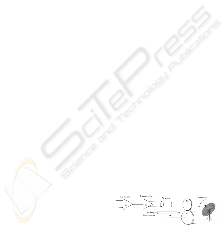
For example, consider a radar tracking antenna
(as described in Nise (2008)), in which the antenna
dish is driven through a step down gearbox by an
armature controlled D.C. motor as shown in Fig. 1.
The antenna azimuth position is monitored by a
precision potentiometer, the output of which is then
compared with demand signal provided by the radar
system. The error signal – the difference between the
desired position and the measured antenna azimuth
position - is amplified to drive the motor so that the
antenna follows the target motion. In this example,
the amplifiers act as the controller, directing the
activities of the D.C. motor. The D.C. motor is the
processor that affects the antenna position to follow
the target position (also known as the set point). The
antenna azimuth position information from the
potentiometer is the feedback. The antenna position
is the operational condition.
Control systems are ubiquitous, and many control
systems are applied in safety-critical systems and
thus face very high reliability requirements. Control
systems are broadly classified as open-loop and
Figure 1: Radar tracking antenna.
closed-loop control system. An open-loop control
system is controlled directly, and only, by an input
387
Y. Chen T., Kuo F., K. Tam W. and Merkel R. (2011).
TESTING A SOFTWARE-BASED PID CONTROLLER USING METAMORPHIC TESTING.
In Proceedings of the 1st International Conference on Pervasive and Embedded Computing and Communication Systems, pages 387-396
DOI: 10.5220/0003365003870396
Copyright
c
SciTePress
signal, without any feedback from outputs. The
systems that utilize feedback are called closed-loop
control systems. The feedback is used to make
decision about changes to the control signal that
drives the plant (in the case of our example, the
antenna). It is well known that the deliberate use of
feedback can be used to stabilize an otherwise
unstable system, to reduce errors due to input
disturbance and to reduce the sensitivity of the
system performance to changes in parameter values
caused by temperature, aging of hardware, etc. Hence,
most control systems are of the closed-loop type.
Many different control algorithms have historically
been used in control systems, but Proportional-
Integral-Derivative (PID) control (Kuo, 1982) is the
most common control algorithm used in industry and
has been universally accepted in industrial control.
The popularity of PID controllers can be attributed
partly to their robust performance in a wide range of
operating conditions and partly to their functional
simplicity, which allows engineers to configure them
in a simple, straightforward manner. With the
ubiquity of microcontroller technology, PID
controllers are typically implemented by the
embedded software in a microcontroller.
As PID controllers are used in most control
systems, it is important to ensure the reliability of
PID software. Software testing is the primary way in
which the reliability of software is assessed and
improved, and, therefore, effective testing of PID
software is the critical step for a reliable control
system. Testing PID software is a challenging task.
Unlike simple control algorithms, the PID controller
is capable of manipulating the process inputs based
on the history and rate of change of the error signal.
This gives a more accurate and stable control method
but complicates the testing process. As the output can
vary because of the history and the rate of change of
the error signal, it is very difficult to check the
correctness of PID implementation from its outputs.
This is known as the oracle problem in software
testing. Recently, the technique of metamorphic
testing has been proposed for testing software
without the need of an oracle (Chan, Chen, Lu, Tse &
Yao (2006); Chen, Cheung & Yu (1998); Chen, Tse
& Zhou (2002); Zhou, Huang, Tse, Yang, Huang &
Chen (2004)). This technique identifies some
necessary properties of the application domain as
metamorphic relations (MRs), that (as discussed in
Section 2) express relationships between multiple
executions, with different inputs, of the software
under test. In metamorphic testing, testers check the
MRs among multiple executions of the program
being tested – if the MRs do not hold, this indicates a
software fault.
In this paper, we study the application of
metamorphic testing to alleviate the oracle problem
of testing PID controller software. We present a case
study on the testing of the PID controller software
embedded in an ATMEL ATmega128
microcontroller. The PID controller software was
implemented in C based on the free sample code
provided by ATMEL Corporation (Atmel
Corporation, 2006). To verify the effectiveness of
using metamorphic testing in the embedded software
for control engineering, we conducted our
experiments in the control of antenna azimuth
position. Instead of building the actual antenna
azimuth position control system, we simulated the
system in the embedded platform using Z-transform.
This approach eliminates the measurement error in
the mechanical position measurement and avoids
hardware faults interfering with the testing of the PID
controller software.
The rest of the paper is organized as follows. In
Section 2 we briefly present the technique of
metamorphic testing. Section 3 presents the basic
design of the PID controller. In Section 4, we identify
four MRs for PID controllers. We then apply the
technique of metamorphic testing to test the software
of a PID controller. Section 5 briefly analyzes
threats to validity. Section 6 concludes our paper by
considering the implications of the work and
identifying opportunities for future research.
Detailed justification of the MRs are provided in the
Appendix.
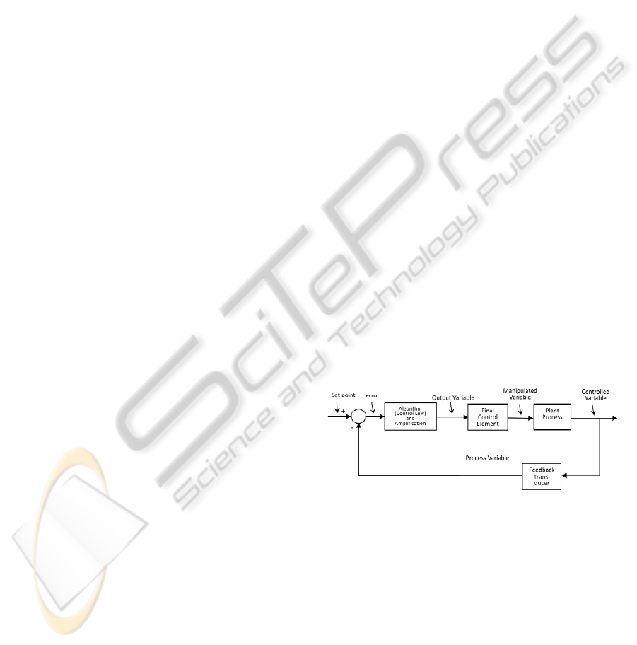
Figure 2: Feedback control system.
2 METAMORPHIC TESTING
Metamorphic testing (Chen, Cheung & Yiu, 1998) is
a property-based approach to software testing. It does
not check the correctness of individual outputs.
Instead, it checks metamorphic relations among
multiple executions of the target program. A
metamorphic relation (MR) is an expected relation,
which is identified from the necessary properties of
application domain, over a set of distinct input data
PECCS 2011 - International Conference on Pervasive and Embedded Computing and Communication Systems
388

and their corresponding output values for multiple
executions of the target program. In theory, a
program should satisfy all the necessary properties if
implemented correctly. Any program which violates
the MRs contains faults.
Let us consider a function f. Suppose R
f
denotes
some properties of f that can be expressed as a
relation among a series of the function’s inputs x
1
,
x
2
, …, x
n
, where n > 1, and their corresponding
values f(x
1
), f(x
2
), …, f(x
n
). The relation R
f
is called a
metamorphic relation. For instance, consider the sine
function. For any two inputs x
1
and x
2
such that x
1
+
x
2
=
π
, we must have sin(x
1
) = sin(x
2
). This property
can be a metamorphic relation for testing the
correctness of the sine function. It can be written as
R
sin
: If x
1
+ x
2
= π, then sin(x
1
) = sin(x
2
)
To verify this relation, two executions are needed.
The first input to sine function is a real number x
1
,
followed by a second input x
2
=
π
- x
1
.
In summary, even if a testing oracle does not
exist, metamorphic testing can still be applied as it
checks the relations among the inputs and outputs of
more than one execution of the program.
3 PID CONTROLLER
As discussed in Section 1, a control system is a
device that monitors and affects the operational
conditions of a given dynamical system.
A generalized block diagram for a feedback
control loop is shown in Fig. 2. The plant process is
the process or device that acts on the system; in the
context of the radar antenna it is the DC control
motor. The feedback transducer, in turn, measures
the current state of the system under control – for the
antenna system, the potentiometer position sensor.
The role of the controller is therefore to: (a) enable
the desired value of output to be set, (b) accept the
measured output value from the feedback transducer,
(c) generate the error (deviation between desired and
present output) signal, (d) amplify and process the
error signal to provide a suitable input to the final
control element.
Figure 3: Block diagram of general PID control system.
The PID controller is the most common solution
because of its simplicity of implementation and good
performance. Fig. 3 shows the block diagram of a
general PID control system. As can be seen, the
output value at time t, u (t) of a PID controller is
governed by the following equation (Atmel
Corporation, 2006):
() () ()
()
⎟
⎟
⎠
⎞
⎜
⎜
⎝
⎛
++=
∫
dt
tde
Tde
T
teKtu
d
t
i
p
0
1
σσ
(1)
This can be easily considered as the sum of three
terms, governed by three key parameters: the
proportional parameter K
p,
the integral parameter K
i
,
and the derivative parameter K
d
. The integral and
derivative terms can also be equivalently expressed
as “action times” T
i
and T
d
respectively. The three
terms are as follows:
Proportional term:
()
teK
p
×
Integral term:
() ()
∫∫
×=×
σσσσ
deKde
T
K
i
i
p
Derivative term:
() ()
te
dt
d
Kte
dt
d
TK
ddp
×=××
In control theory, a continuous control system is
usually represented by a Laplace transformed s-
transfer function. The s-transfer function of PID
controller can be expressed as follows:
() ()
sEsT
sT
Ksu
d
i
p
⎟
⎟
⎠
⎞
⎜
⎜
⎝
⎛
++=
1
1
where u(s) is the Laplace transform of the controller
output u(t) and E(s) is the Laplace transform of error
signal e(t).
Not all controllers necessarily make use of all
three terms in the PID control formula. While all
controllers use some level of proportional control
(and thus have a non-zero K
p
), in different
applications the integral and derivative terms may or
may not be used.
P control, on its own, is the simplest form of
control. If the parameter K
p
is increased, it reduces
the errors inherent in the system. The maximum
value of K
p
is limited due to the onset of instability
(that is, the controller failing to reach a steady state).
PI control, involving both the proportional and
integral terms, can reduce the steady-state error (the
difference between the actual final state and the
desired final state). PD control, involving both
proportional and derivative terms is used to improve
the dynamic performance of the loop, to improve
TESTING A SOFTWARE-BASED PID CONTROLLER USING METAMORPHIC TESTING
389

stability and speed up the time response. PID control
combines all three forms of control. It can eliminate
the steady-state error and improve the dynamic
performance.
Digital controllers are widely available at low
cost and are consequently in widespread use. These
range from small inexpensive single board
controllers having a limited amount of input/output
facilities and memory, and a small high level
language instruction set, to powerful microcomputers
or programmable logic controller (PLC) capable of
controlling many control loops. There are many
advantages in using digital controllers, including:
• The possibility of a wide range of control
algorithms.
• The ability to change algorithm parameter
values easily by software without modifying
any hardware.
• The ability to make the system adaptive.
• The ability to compensate for process non-
linearity by non-linear control algorithms.
• The ease of implementing arithmetic
operations.
Unlike analogue controllers, digital controllers
use discrete, periodic sampling from the feedback
transducer. It is important for the intervals between
sampling to be small enough – or, in other words, the
sample frequency to be high enough - so that the
sampled points represent the continuous signal
accurately enough. If the maximum frequency
presents in the signal is
ω
, the theoretical minimum
sampling frequency should be 2
ω
(Nyquist, 1928).
Consider a control system as shown in Fig. 3, the
PID controller is a digital controller implemented by
the embedded software in a microcontroller. At time t,
the digital PID controller will read the error e(t),
calculate and output the control input u(t) to the
system. The process repeats at intervals defined by
the sample period T. At time t, n = t/T such cycles
have occurred; in other words, t=nT.
When implementing a software-based digital PID
controller, the continuous integrals are approximated
using summations. The integral term is approximated
as follows:
() ()
∑
∫
=
≈
n
k
t
keTde
0
0
σσ
The derivative term is approximated by the
following equation:
() () ( )
T
nene
dt
tde 1−−
≈
This gives the controller:
(2)
where
i
p
T
K
i
K = and
dpd
TKK =
.
Figure 4: Block diagram of antenna azimuth position
system with PID control.
Most software PID controllers are implemented
based on formula (2).
4 TESTING PID SOFTWARE
USING METAMORPHIC
TESTING
4.1 Experimental Subject
The PID controller software being tested is based on
the sample code revision 456 dated 16 Feb. 2006
provided by ATMEL Corporation (Atmel
Corporation, 2006). The code comprised 478 lines of
C code, and was compiled using the IAR EWAAVR
4.11A compiler for the ATMEL AVR
microcontrollers. In our experiment, we chose the
AVR ATMega128 microcontroller to run the PID
software.
4.2 Experimental Setup
We used an antenna azimuth position system, as
shown in Fig. 4, in our experiment. The process plant
in the block diagram is a mechanical system with
D.C. motor, gear and potentiometer.
Instead of using a real antenna azimuth position
system, we simulated the antenna azimuth position
system in the embedded platform. The behavior of
the system is described using z-transfer functions
(Kuo (2006), p51). The block diagram of the
experimental system is shown in Fig. 5. Aside from
the obvious convenience of not requiring an actual
radar antenna system for our experiments, there are
many advantages of using a simulation platform to
replace the actual system:
()
)1()()()()(
0
−−++=
∑
=
neneKkeKneKnu
d
n
k
ip
PECCS 2011 - International Conference on Pervasive and Embedded Computing and Communication Systems
390
• Hardware problems in antenna azimuth
position system are eliminated when testing
the PID controller software.
• The system outputs are monitored easily to
verify the performance of the PID controller
without using expensive testing equipment.
• The system parameters can be varied easily.
• A wide range of test cases can be selected in
the simulation platform without the need to
consider hardware limitations.
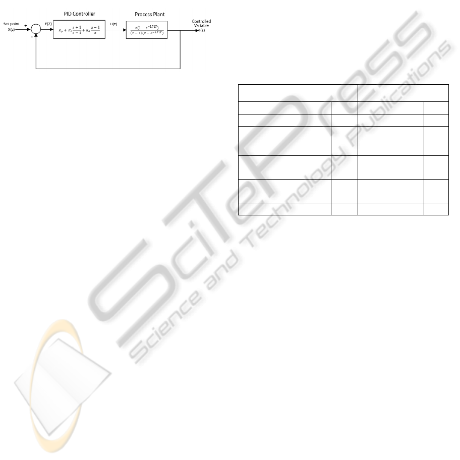
Figure 5: Block diagram of antenna azimuth position
system with PID control in z-transfer functions.
We conducted the experiments by loading the
PID controller application and the antenna azimuth
position system simulation to an ATmega128
microcontroller on a STK501 development board.
We used the AVR studio and JTAGICE Mk II
development tools supplied by Atmel Corporation.
The output of the PID controller is sent to the input
of the simulated antenna azimuth position system on
the STK501 development board. The STK501 was
connected through an RS232 serial interface to a PC,
which runs terminal emulation software to capture
the system output and store the data in a text file.
4.3 Input and Output Parameters of
PID Control System
The inputs and outputs to the system that were used
to control and evaluate the system are summarized in
Table 1.
4.3.1 Inputs
• The set point x is the reference input of the
system.
• The system status y is the (simulated) output
of the system position sensor, which acts as
feedback to compare with the set point in the
control system.
• The proportional parameter K
p
, also known
as the gain, controls the proportional
response by the control system to the error
signal as described in Section 3.
• The integral parameter K
i
is sometimes
called integral gain, controls the contribution
of the integral term to the overall control
response, as described in Section 3.
• The derivative parameter K
d
is sometimes
called derivative gain which determines the
magnitude of contribution of the derivative
term to the overall control action.
• The sampling period T is the time period the
digital system samples the analog signal
input.
4.3.2 Outputs
• The settling time ts is the time for the
transient’s damped oscillations to reach ±2%
of the steady-state value.
Table 1: Input and outputs of PID control system.
Inputs Outputs
Set point x Settling time ts
System status y Peak time tp
Proportional
parameter
K
p
Rise time tr
Integral parameter K
i
Percentage
overshoo
t
os
Derivative
parameter
K
d
Steady state
error
ess
Sampling period T
• The peak time tp is the time required to reach
the first or maximum peak.
• The rise time tr is the time required for the
waveform to go from 0.1 of the final value to
0.9 of the final value.
• The percentage overshoot os is the amount
that the waveform overshoots the steady-
state, or final value, at the peak time,
expressed as percentage of the The steady
state error ess is the system output error
when the system is in steady state. It is used
to measure the accuracy of the control
system.
4.4 Metamorphic Relations
for Testing of PID Controllers
We have identified four MRs for testing the PID
controller from the properties of the PID control
stated in Section 3.
In this section, we present an explanation of our
metamorphic relations. In some cases, the full
mathematical justifications for our metamorphic
relations are quite complex, and are thus presented in
the Appendix.
TESTING A SOFTWARE-BASED PID CONTROLLER USING METAMORPHIC TESTING
391

In the following, subscripted variables indicate
whether the parameter refers to the source test case or
follow up test case. For instance, tr
1
refers to the rise
time output for the source test case, and tr
2
refers to
the rise time for the follow-up test case.
Metamorphic Relation 1
It is obvious that the larger the difference between set
point and system status the longer the settling time is
needed. Based on this property, we can identify a
metamorphic relation denoted MR1 as follows:
MR1:
If (x
1
– y
1
)< (x
2
– y
2
) then
ts
1
< ts
2
,
Metamorphic Relation 2
For a pure P controller — that is, one where K
i
=0
and K
d
=0 — if the proportional coefficient K
p
increases, the rise time tr will decrease. Furthermore,
the maximum overshoot will increase, and the
steady-state error will decrease (see the Appendix for
a full mathematical analysis of these propositions).
Hence, we define MR2 as follows:
MR2:
If (K
p1
< K
p2
)∧(K
i1
= K
i2
=0)∧(K
d1
= K
d2
=0) then
(tr
1
≥ tr
2
) ∧ (os
1
< os
2
) ∧ (ess
1
≥ ess
2
)
Metamorphic Relation 3
Increasing the integral term has the effect of reducing
the steady-state error (see the Appendix for a full
explanation). However, it can also cause the present
value to overshoot the set point value and slow the
settling time, since the integral term responds to the
accumulated error from the past. MR3 is therefore
defined as follows:
MR3:
If K
i1
< K
i2
then
(os
1
< os
2
) ∧ (ess
1
≥ ess
2
) ∧ (ts
1
≤ ts
2
)
Table 2: Input Parameter Ranges for PID Controller.
Input Parameters
Range for
Original Test
Cases
Range for
Follow-up
Test Cases
Set point, X(z) [1, 8] [2,10]
Proportional gain, K
p
[1, 8] [2, 10]
Integral constant, K
i
[0.001, 0.006] [0.002, 0.01]
Derivative constant,
K
d
[0, 8] [0.5, 10]
Metamorphic Relation 4
Since
()
te
dt
d
represents the slope of e(t), the
derivative control is essentially an anticipatory type
of control. Normally, in a linear system, if the slope
of e(t) due to a step input is large, a high overshoot
will subsequently occur. The derivative control
measures the instantaneous slope of e(t), predicts the
overshoot ahead of time, and makes a proper
correcting effort before the overshoot actually occurs.
As a result, the increase of K
d
will reduce the
overshoot. It is apparent that the derivative control
will affect the steady-state error of a system only if
the steady state error varies with time. If the steady-
state error of a system is constant with respect to time,
the time derivative of this error is zero, and the
derivative control has no effect on the steady-state
error. If K
d
is increased, the steady state error will
decrease or remain the same. As the increase of K
d
will decrease the overshoot, the settling time will be
decreased with the increase of K
d
. We can therefore
define MR4 as follows:
MR4:
If K
d1
< K
d2
then
(ts
1
≥ ts
2
) ∧ (os
1
≥ os
2
) ∧ (ess
1
≥ ess
2
)
4.5 Testing Procedures
We tested the embedded software of PID controller
using a typical position control application for
antenna. As mentioned in Section 4.2, we used a
simulated antenna azimuth position system instead of
a real antenna system. We then modeled the transfer
function of the real antenna system as indicated in
Fig. 4 with the z-transfer function as indicated in Fig.
5 and then implemented it using a difference
equation in C on the embedded platform. The
difference equation of the antenna azimuth position
system is
y(n) = 0.0006612x(n) + 1.9983y(n-1) – 0.9983y(n-2)
where n is the discrete step at time t with a sampling
period of T.
We then used the AVR studio and JTAGICE Mk
II to load the PID controller application and the
antenna azimuth position system simulation into the
flash memory of ATMega128 microcontroller on a
STK501 development board. The output of the PID
controller is sent as the input of the simulated
antenna azimuth position system in the STK501
development board. The output of the antenna system
is captured by a terminal application running on a PC
connected to the STK501 board through the serial
PECCS 2011 - International Conference on Pervasive and Embedded Computing and Communication Systems
392
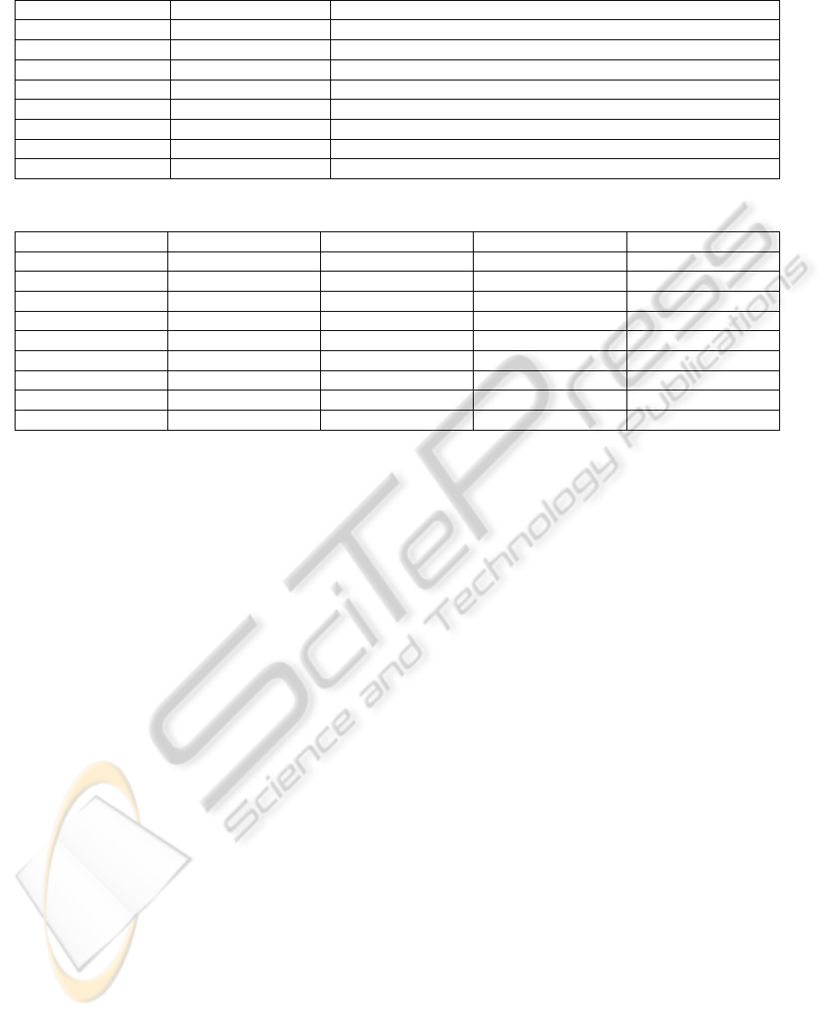
Table 3: Mutants of PID Controller.
Mutant Modified line # Fault description
Mu1 103 Replacement of + by – in pid.c
Mu2 95 Replacement of pid_st->sumError by error in pid.c
Mu3 80 Replacement of * by + in pid.c
Mu4 103 Replacement of + by * in pid.c
Mu5 99 Replacement of - by / in pid.c
Mu6 94 Replacement of + by * in pid.c
Mu7 103 Replacement of i_term by p_term
Mu8 103 Replacement of p_term by i_term
Table 4: Proportion of Test Cases That Killed Mutants Using Metamorphic Relations.
MR1 MR2 MR3 MR4
Original
0% 0% 0% 0%
Mutant 1
0% 0% 1% 100%
Mutant 2
0% 0% 37% 0%
Mutant 3
99% 0% 40% 42%
Mutant 4
98% 0% 100% 0%
Mutant 5
95% 0% 1% 100%
Mutant 6
0% 0% 100% 0%
Mutant 7
0% 0% 100% 0%
Mutant 8
17% 100% 100% 0%
interface.
As mentioned in Section 3, the selection of the
ranges of set point x, K
p
, K
i
and K
d
were chosen to
ensure that the resulting system is stable. We
performed a number of simulations of the control
system as shown in Fig. 5 to define the range of input
parameters as listed in Table 2 for stable operation.
These ranges were used to determine bounds for the
generation of input parameters. As the sampling
interval T is not present in our metamorphic relations,
and its effects on computation can also be achieved
by varying the gain constants, it was set as a constant
at 10 milliseconds for all test cases. Similarly, as the
behavior of the PID controller depends on the
difference between the Set point and the initial
system status (y), for simplicity y was set at 0 for all
test cases.
100 source test cases were generated by uniform
random sampling within the input ranges as specified
in Table 2. For each source test case, four follow-up
test cases were generated, one for each of the MRs.
To generate a follow-up test case, a random sample
for the varying parameter (for instance, for MR1, the
initial set point X(z)) was generated from the ranges
for the follow-up test cases defined in Table 2. If the
resulting test case met the MR condition (for instance,
that X(z) was increased), the follow-up test case
input was accepted, otherwise the process was
repeated until an eligible follow-up test case was
located.
We initially ran the test cases on the unmodified
source code to determine if there were any pre-
existing faults in it – while this was considered
unlikely, it avoided the possibility of such pre-
existing faults interfering with measurement of the
effectiveness in mutant detection. As no fault was
detected in the original software, we went on to
generate 8 mutant versions of the software to
evaluate the failure-detection performance of
metamorphic testing.
4.6 Mutants
Mutants were generated by transforming the original
code to a mutated code using randomly selected
mutation operator. The program line to mutate is
randomly selected using random number generator.
If the mutation operator cannot be applied for the
selected line, we will search the program lines closest
to it. Table 3 shows the mutant versions of the PID
controller.
4.7 Results
Table 4 shows the proportion of source/follow-up test
case pairs which revealed a violation of the
metamorphic relation (and thus revealed a bug and
“killed the mutant”) for the unmodified source code,
and the eight mutants.
All the mutant versions of the PID controller
were killed by at least one of the MRs with the test
TESTING A SOFTWARE-BASED PID CONTROLLER USING METAMORPHIC TESTING
393

cases available. Mutant 1 violates MR3 and MR4
when tested with 1% and 100% of the test case pairs,
respectively. It is reasonable because the fault of
Mutant 1 is in the sign of derivative term. It therefore
causes a violation of MR4 with 100% of the
generated test cases. Mutant 2’s fault is due to a
single error value instead of the sum of errors in the
integral term. This fault effectively results in the PID
controller acting as a PD controller, causing a 37%
failure rate in the testing associated with MR3. The
proportional gain is added to the error instead of
multiplied by the error in Mutant 3. It does not affect
the direction of effect of proportional parameter, as
the proportional term still increases if the
proportional parameter is increased, and as such
MR2 does not detect the error. Since this mistake
turns the PID controller to another unknown type of
controller, it does not satisfy the relations of MR1,
MR3 and MR4 which hence reveal the error. Mutant
4 has the integral term and derivative term to be
incorrectly multiplied together, instead of added.
Mutant 4 is therefore no longer a PID controller, and
so MR1 and MR4 are violated with most test case
pairs. As MR2 relates to the change of K
p
which is
unaffected by this seeded fault, and the integral term
of dominates the effect of derivative term, MR2 and
MR4 cannot detect the fault. Mutant 5 relates to a
fault in the derivative term, so it is understandable
that there is a violation of MR4 in 100% of test case
pairs. Since MR1 relates to all the parameters, it is
also affected. MR3 is a summation of all sampled
errors, so it is violated in some test cases. Mutant 6
and Mutant 7 change the integral term calculation, so
MR3 is violated in 100% of cases. The fault in
Mutant 8 is the replacement of the proportional gain
by the integral parameter. It is therefore
understandable that MR2 and MR3 are violated in
100% of the test case pairs.
5 THREATS TO VALIDITY
5.1 Internal Validity
The only major threats to the internal validity of this
study are incorrect implementation of the code
simulating the antenna motor and sensor, and the
various pieces of experimental scaffolding used to
generate test cases and collect results. The motor
simulation required very few lines of code, and was
tested to ensure that it reflected the expected
behavior. The experimental scaffolds are also very
simple. The PID controller itself was, as noted,
sample code and not implemented by the authors.
5.2 External Validity
The “bugs” detected by the metamorphic relations
were mutations deliberately seeded into the controller
code. While at least one study suggests a connection
between the failure behavior of mutants and “real”
bugs (Daran & Th’evenod-Fosse (1996)) we cannot
be certain such a connection generalizes to controller
software.
While the metamorphic relations demonstrated
here should be applicable to most applications in
which a PID controller is used, it is uncertain how
they will perform in revealing actual bugs in real
systems. It is also uncertain whether effective
metamorphic testing can be achieved on other types
of controllers. While the extensive mathematics
underpinning control theory should make it relatively
straightforward to derive metamorphic relations for
other types of controllers, further studies will be
required to demonstrate efficacy.
6 CONCLUSIONS
Software-based control systems in general, and PID
controllers in particular, are widely deployed
technologies. It is therefore crucial that they are
demonstrated to be reliable before deployment.
However, they can be difficult to test effectively as
verifying the outputs is subject to the oracle problem.
We have demonstrated the ability to effectively kill
mutants in a PID controller using metamorphic
testing; all eight mutants tested were killed by at least
one metamorphic relation.
A key question for the industrial application of
metamorphic testing is the ease with which effective
MRs can be found. In the case of the PID controller,
control theory made it relatively straightforward for a
domain expert to find suitable MRs. This is
consistent with studies in other problem domains,
where suitable MRs have been reasonably readily
identified.
However, it is worth considering the relative
effectiveness of the four metamorphic relations. The
most effective was MR3, which relates to the integral
term. It was able to kill all eight mutants. As the
integral term consists of the summation of the entire
error signal (and thus the behavior of the controller
over the entire time scale), it makes sense that it
revealed more mutants than other MRs. By contrast,
MR2, which relates to the proportional term and thus
depends only on the instantaneous error, revealed
only one mutant. To maximize the effectiveness of
metamorphic testing, it would obviously be desirable
PECCS 2011 - International Conference on Pervasive and Embedded Computing and Communication Systems
394
to have some way to identify MRs that are more
likely to find faults.
Our study concentrated entirely on the testing of
the controller software, and simulated “perfect”
hardware. In practice, hardware may of course have
faults. Metamorphic testing could be used to test the
complete system, including hardware. However, it is
not clear whether the metamorphic relations used
here are useful in detecting hardware faults – and, if
the present MRs are unsuitable, whether there are
others that can provide useful fault-finding
capabilities beyond existing techniques. This is
clearly an area worthy of future study.
We believe that our study provides good evidence
of the promise of metamorphic testing in control
applications. However, there are more advanced
control systems that control higher order attributes
(for instance, in a mechanical system, speed and
acceleration). We propose to conduct further studies
to demonstrate that these, too, can be effectively
tested without an oracle using metamorphic testing
techniques.
ACKNOWLEDGEMENTS
This project was supported by an ARC Discovery
Project (ARC DP 0984760).
REFERENCES
Application Note AVR221, “Discrete PID controller”,
Atmel Corporation, 2006. Retrieved from: http://www.
atmel.com/dyn/products/app_notes.asp?family_id=607
W. K. Chan, T. Y. Chen, H. Lu, T. H. Tse and S. S. Yau,
“Integration testing of context-sensitive middleware-
based applications: a metamorphic approach”,
International Journal of Software Engineering and
Knowledge Engineering. Vol. 16(5), 2006, pp. 677-
703.
T. Y. Chen, S. C. Cheung and S. M. Yiu, “Metamorphic
testing: a new approach for generating next test cases”
Technical Report HKUST-CS98-01, Department of
Computer Science, Hong Kong University of Science
and Technology, Hong Kong, 1998.
T. Y. Chen, T. H. Tse and Z. Q. Zhou, “Semi-proving an
integrated method based on global symbolic
evaluation and metamorphic testing”, in Proc. ACM
SIGSOFT International Symposium on Software
Testing and Analysis (ISSTA 2002) (ACM Press,
2002), pp. 191-195.
M. Daran and P. Thévenod-Fosse, “Software Error
Analysis: A Real Case Study Involving Real Faults
and Mutations,” ACM SIGSOFT Software
Engineering Notes, vol. 21, no. 3, pp. 158–177, May
1996
B. C. Kuo, Automatic Control Systems, 4th edition, 1982,
Prentice-Hall, inc., Eaglewood Cliffs, N. J., U.S.A.
Chapter 8.2, pp. 471-483.
N. S. Nise, Control Systems Engineering, Fifth Edition,
2008, Wiley.
H. Nyquist, "Certain Topics in Telegraph Transmission
Theory", AIEE Trans., vol. 47, pp. 617-644, 1928.
Z. Q. Zhou, D. H. Huang, T. H. Tse, Z. Yang, H. Huang
and T.Y. Chen, “Metamorphic testing and its
applications”, in Proc. of the 8
th
International
Symposium on Future Software Technology
(ISFST2004), Software Engineers Association, Japan
2004.
APPENDIX: DERIVATION
OF SOME METAMORPHIC
RELATIONS
In this appendix, we follow the notation used in
Table 1.
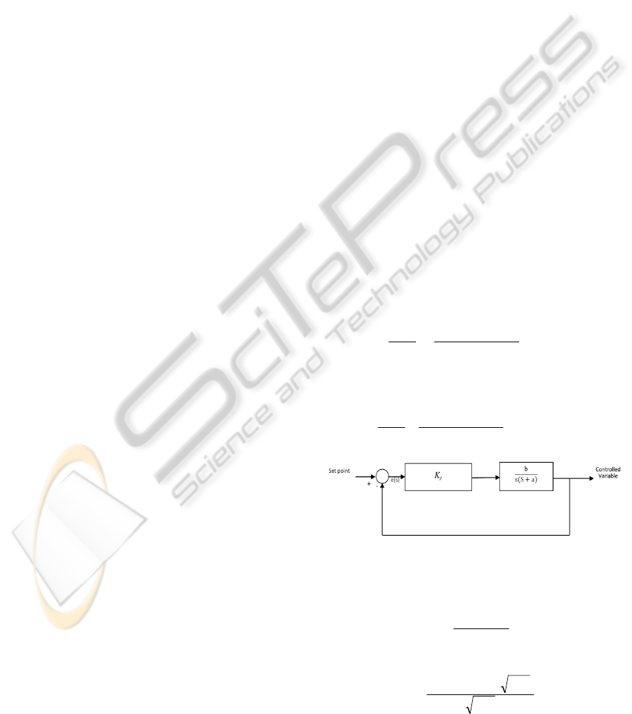
Metamorphic Relation 1
Consider a P controller (that is, a PID controller
where the integral and derivative parameters are 0)
controlling a second order plant as shown in Fig. 6,
the closed loop transfer function will be
()
()
=
++
(3)
For any second order control system with the general
closed loop transfer function of
()
()
2
2
2
2
n
n
ss
sX
sY
ωξω
ω
++
=
(4)
Figure 6: General P control system.
The rise time tr can be obtained by the following
approximation:
η
ω
ξ
5.28.0 +
≅tr
From equations (3) and (4), we have
(
)
bK
bKa
tr
p
p
2/5.28.0 ×+
≅
TESTING A SOFTWARE-BASED PID CONTROLLER USING METAMORPHIC TESTING
395

Increasing K
p
will decrease the rise time tr.
For any second order control system, the maximum
overshoot can be obtained as:
2
1
100max
ξ
ξ
−
−
×=
n
eos
From equations (3) and (4), we obtain
2
/
2
100 maximum
abK
bK
na
p
p
eos
−
−
×=
When K
p
increases, maximum overshoot increases.
From Fig. 6, for step input with the error
(
)
=
,
the steady state error can be obtained as follows:
()
pp
s
KaK
as
e
1
lim
0
=
+
=∞
→
When K
p
increases, the steady state error decreases.
Therefore, we have:
MR2:
If (K
p1
< K
p2
) ∧ (K
i1
=K
i2
=0) ∧ (K
d1
=K
d2
=0)
then (tr
1
≥ tr
2
) ∧ (os
1
< os
2
) ∧ (ess
1
≥ ess
2
)
Metamorphic Relation 2
The integral term added to the proportional term is
equivalent to adding a zero at s = -K
i
/K
p
and a pole at
s = 0 to the open loop transfer function.
The transfer function will be
()
()
()
sX
K
K
sbass
K
K
sb
sY
i
p
i
p
⎟
⎟
⎠
⎞
⎜
⎜
⎝
⎛
+++
⎟
⎟
⎠
⎞
⎜
⎜
⎝
⎛
+
=
2
Then
()
()
()
()
sX
K
K
sbass
ass
sE
i
p
⎟
⎟
⎠
⎞
⎜
⎜
⎝
⎛
+++
+
=
2
2
For a step input with magnitude X, the steady state
error is:
()
()
()
bK
XK
X
K
K
sbass
ass
e
p
i
i
p
⋅
⋅
=
⎟
⎟
⎠
⎞
⎜
⎜
⎝
⎛
+++
+
=∞
→
2
2
0s
lim
Since K
I
< 1, it will then reduce the steady state error.
Since the integral term is responding to accumulated
errors from the past, it can cause the present value to
overshoot the set point value and slow the settling
time. MR3 is therefore defined as follows:
MR3:
If K
i1
< K
i2
then
(os
1
< os
2
) ∧ (ess
1
≥ ess
2
) ∧ (ts
1
≤ ts
2
)
Metamorphic Relation 3
Since de(t)/dt represents the slope of e(t), the
derivative control is essentially an anticipatory type
of control. Normally, in a linear system, if the slope
of e(t) is large due to a step input, a high overshoot
will subsequently occur. The derivative control
measures the instantaneous slope of e(t), predicts the
large overshoot ahead of time, and makes a proper
correcting effort before the overshoot actually
occurs. As a result, the increase of K
d
will reduce the
overshoot. It is apparent that the derivative control
will affect the steady-state error of a system only if
the steady state error varies with time. If the steady-
state error of a system is constant with respect to
time, the time derivative of this error is zero, and the
derivative control has no effect on the steady-state
error. The increase of K
d
will not increase the steady
state error. As the increase of K
d
will decrease the
overshoot, the settling time will be decreased with
the increase of K
d
. We can therefore define MR4 as
follows:
MR4:
If K
d1
< K
d2
then
(ts
1
≥ ts
2
) ∧ (os
1
≥ os
2
) ∧ (ess
1
≥
ess
2
)
PECCS 2011 - International Conference on Pervasive and Embedded Computing and Communication Systems
396
