
REAL-TIME TERRAIN RENDERING WITH INCREMENTAL
LOADING FOR INTERACTIVE TERRAIN MODELLING
Simon van den Hurk, Wallace Yuen and Burkhard C. W
¨
unsche
Department of Computer Science, University of Auckland, Private Bag 92019, Auckland, New Zealand
Keywords:
Terrain rendering, Terrain modelling, Sketch-based interfaces, GPU-acceleration.
Abstract:
Real-time terrain rendering techniques usually employ static data structures and do not allow interactive modi-
fication of the terrain. In this paper we describe a real-time geometric clipmapping terrain rendering technique
for large terrains which allows incremental updates of the underlying data structure. We have combined the
method with an interactive sketch-based terrain modelling technique. The clipmap data structure is updated
during runtime to synchronise the terrain visualization with changes to the underlying digital elevation map.
Tests and examples demonstrate the advantages of our method over traditional approaches. Disadvantages and
limitations are discussed and suggestions for future work are presented.
1 INTRODUCTION
Terrains are an essential part of virtual environments
in computer games, movies, visual impact studies, ar-
chitecture, urban design and archaeology. In order
to achieve real-time rendering multi-resolution repre-
sentations are necessary. A popular representation is
to use a regular grid of height values, also called Dig-
ital Elevation Map (DEM), where grid points are con-
nected by triangles. A multi-resolution representation
represents the same height field using different layers
with a decreasing number of triangles with increasing
size. When rendering the terrain regions close to the
view point are represented in high resolution, and re-
gions far away in low resolution, so that the size of tri-
angles projected onto the view plane is approximately
constant for the entire terrain.
In most applications the underlying multi-
resolution terrain data structures are static and do not
allow modification of the terrain in real-time. In re-
cent years an increasing number of applications have
been developed requiring interactive terrain mod-
elling, e.g. in architecture, geology, and archaeol-
ogy (Keymer et al., 2009). In this paper we describe
a real-time geometric clipmapping terrain rendering
technique for large terrains which allows incremental
updates of the underlying data structure.
Section 2 reviews existing terrain rendering tech-
niques. Section 3 introduces the geometric clipmap-
ping algorithm, which forms the foundation of our
proposed technique. Section 4 presents our solution
and section 5 presents its evaluation. We conclude
this paper and suggest directions for future work in
section 6.
2 LITERATURE REVIEW
Terrain rendering techniques have been extensively
studied since the mid 1990s and can be categorised
into methods using tile based data structures, quad-
tree based triangle hierarchies and out-of-core ap-
proaches. Initial work improved computation time
by reducing the level of detail with increasing view-
point distance (Lindstrom et al., 1995; Duchaineau
et al., 1997). De Boer recognised that rendering
speed can be improved dramatically by using graph-
ics hardware, which requires different data structures
and algorithms. The resulting Geometrical MipMap-
ping (de Boer, 2000), divides the terrain in multiple
chunks of different levels of detail. These chunks are
then updated as the user moves throughout the simu-
lation. Additional work involving out-of-core terrain
rendering (Schneider and Westermann, 2006) uses
tiles and a nested mesh hierarchy to avoid mesh re-
triangulation. A comprehensive survey of terrain ren-
dering techniques is presented in (Pajarola and Gob-
betti, 2007).
Early work on terrain editing includes multi-
resolution detail patches devised by (He et al., 2002).
(Atlan and Garland, 2006) modify the terrain in real-
181
van den Hurk S., Yuen W. and Wünsche B..
REAL-TIME TERRAIN RENDERING WITH INCREMENTAL LOADING FOR INTERACTIVE TERRAIN MODELLING.
DOI: 10.5220/0003366901810186
In Proceedings of the International Conference on Computer Graphics Theory and Applications (GRAPP-2011), pages 181-186
ISBN: 978-989-8425-45-4
Copyright
c
2011 SCITEPRESS (Science and Technology Publications, Lda.)

time by specifying editing strokes, in which quadtree
hierarchy is used to represent the heightmap for mul-
tiresolution editing. (Bhattacharjee et al., 2008) im-
prove performance by utilising the GPU for render-
ing and editing the terrain simultaneously. The au-
thors use a fragment shader to operate on each height
value, and every time the terrain undergoes deforma-
tion or modification, the parameters of the actual pro-
cess are parsed into the shader, which could be a re-
sult of simulation of terrain dynamics or direct editing
performed by user using input devices such as mice.
(Dan et al., 2009) discuss various ways of terrain
editing, including geometric editing and texture edit-
ing. Similar to (Bhattacharjee et al., 2008), they also
modify the height point, but add natural looking varia-
tions by defining new height values using an outer and
inner radius and a parameter determining the radius.
We add to this work by providing an incremental up-
date technique which enables interactive terrain mod-
elling by minimizing data transfer and data structure
updates in GPU memory.
3 GEOMETRY CLIPMAPS
Geometry Clipmaps is a level-of-detail GPU-based
terrain rendering technique (Losasso and Hoppe,
2004; Asirvatham and Hoppe, 2005). It uses multiple
representations of the same terrain at different resolu-
tions to increase the efficiency of the rendering pro-
cess. The clipmaps data structure is broken into sev-
eral layers, each of which contains a higher resolution
than the layer below it. These layers are arranged by
centering them about the viewpoint and then render-
ing them. The terrain data is stored in a vertex buffer
object and updated as the viewpoint moves through-
out the simulation. This grid of data is stored using
an offset into the vertex buffer object to allow for a
toroidal access. By using a toroidal index the vertex
buffer object is able to only update a single column
or row rather than moving all rows or columns within
the vertex buffer object to a new location.
The update process examines each level in the
clipmap, starting from the lowest resolution and iter-
ating to the highest. Each level uses the viewpoint
of the camera to determine an active region of the
clipmap. If this active region differs from the previ-
ous update’s active region, then the vertex buffer ob-
ject is updated, and the data will be synchronised with
the terrain data that is stored within the RAM mem-
ory. When the terrain is rendered, each clipmap layer
renders a ring section within which the next clipmap
layer is rendered. The resolution decreases with in-
creasing distance from the viewpoint.
The most important aspect of the clipmaps data
structure is the way clipmap layers are blended to cre-
ate smooth transitions between them. The vertex in-
formation of the terrain stored by each clipmap layer
includes not only the x, y, and z coordinates of each
point in the terrain, but also an additional channel con-
taining the height of the parent layer at this point.
During the render method, an alpha value is calcu-
lated to interpolate between the vertex height and the
parent vertex height. The alpha value approaches one
for the vertices that are closer to edge of the clipmap,
therefore aligning the edge of the clipmap with the
edge of its parent clipmap layer.
4 DESIGN
In order to interactively model terrains we need a
technique with suitable data structures, which can be
modified to support interactive updates, and with as
few constraints as possible when using it. After care-
ful analysis we chose the Geometry Clipmaps algo-
rithm (Asirvatham and Hoppe, 2005). A major advan-
tage is that the algorithm performs well when viewed
from a top down perspective, which is important dur-
ing modelling, e.g., to add and view terrain structures
such as mountain ranges and rivers. The algorithm
also loads large sections of terrain, allowing for a
fast rotation of the viewpoint without a large com-
putational requirement. The algorithm merges well
with the sampling technique that the sketch based in-
put provides. The geometry clipmaps algorithm uses
multiple levels of detail and the sketch based input can
provide these different levels by sampling the con-
tours at different resolutions. Real-time incremental
updating of the terrain is achieved by computing small
clipmap sections fitting into multiple resolution repre-
sentations and as such minimizing the amount of data
passed between the RAM and graphics card memory.
4.1 Data Structures
The data for the surface of the terrain will be stored
within the RAM memory during the runtime of the
program. In order to access the terrain data and pro-
vide it to the clipmaps data structure, we wrote the
TerrainSurface interface.
The clipmaps algorithm requires different repre-
sentations of the same terrain at different resolutions.
The desired representations are obtained by calling
the methods within this interface with a Dimension
parameter. The terrain data is stored in RAM using
a one-dimensional array of floats. This packed data
is then accessed using offsets within the data. A data
GRAPP 2011 - International Conference on Computer Graphics Theory and Applications
182

stride value is required to determine the byte offset
between vertex and normal data. The interface de-
scribes the methods providing access to the different
types of data required by the clipmaps algorithm:
• Vertex information.
• Normal Information.
• Parent Normal Information.
• Offsets to the position of the above information
within the single dimensional array.
By using offsets into the one dimensional array
the interface provides flexibility for implementations
which already contain a set structure for the order of
the data stored in the packed array.
The implementation of the clipmaps algorithm
is split into two separate classes: Clipmaps and
Clipmap (van den Hurk et al., 2011). The Clipmaps
class provides the interaction with the clipmaps con-
cept and is the class instantiated by the end user. This
class manages the updating of all levels of the clipmap
data structure, as well as providing simple method
calls to render the entire data structure.
The Clipmap class provides implementation for a
single layer of the clipmaps data structure. Each layer
of the clipmap is stored in a series of vertex buffer ob-
jects within the memory of the graphics card. This
class provides core methods to create these vertex
buffer objects, and to update them as the viewpoint is
moved throughout the scene. It also provides methods
to render the terrain and perform the frustum culling
to improve the efficiency.
For this specific project there are some notable
changes from the original geometry clipmaps imple-
mentation. The most important is that no compression
is done upon the terrain data stored in RAM memory,
since the compression algorithm used within the orig-
inal paper is quite quite slow and would prevent in-
teractive frame rates. Another modification is that the
lowest level of the clipmap data structure has been
changed to always render, regardless of the camera
position. In the original implementation the entirety
of the terrain is only rendered when the viewpoint is
in the centre of the terrain. By enforcing the lowest
level to always be drawn, the entire terrain is there-
fore always visible at the lowest resolution regardless
of the viewpoint. Lastly, this implementation allows
non-square shaped clipmaps to be defined, so that the
size of the clipmaps can be rectangular such as 256 x
512.
4.2 Incremental Updates
An interactive terrain modelling system must show
any modifications to the terrain in real-time. The vi-
sual feedback will assist the users with editing the ter-
rain. In order to achieve this, only small rectangular
sections enclosing the modified regions are updated.
4.2.1 Clipmaps Section Update
Updates of the terrain data will change the informa-
tion stored in RAM memory that is interacted with
through the TerrainSurface interface. After a sec-
tion of the terrain stored in RAM memory is updated,
the corresponding data within the graphics card mem-
ory must also be updated. This functionality is pro-
vided through an UpdateSection method within the
Clipmaps class. This method works by defining a
rectangular region that is to be updated and a Dimen-
sion variable which specifies at which resolution the
rectangular region is specified.
Algorithm 4.1: UPDATESECTION(x, y, width, height, updateDimension.)
for i ← 1 to clipmapStack.size − 1
do
clipmap ← clipmapStack[i]
sur f aceResolution ← clipmap.sur f aceResolution
heights ← clipmap.sur f ace.getHeights(sur f aceResolution)
rect ← getClipmapU pdateRegion(x, y, width, height, clipmap)
clipmapRegion ← convertSur f aceToClipmapCoordinates(rect)
updateV BO(clipmapRegion, heights, rect)
aa
As shown in algorithm 4.1, the method iterates
through all clipmap layers in the clipmap stack and
determines the appropriate rectangular region to be
updated by scaling the co-ordinates for each level de-
pending on the surface resolution. The method then
performs a standard update for this region, and lastly
synchronises the data on the graphics card with the
newly updated terrain data in the RAM memory. By
using this method, the amount of data required to be
transferred between the RAM memory and the graph-
ics card memory is reduced to a minimum, reducing
rendering time and saving bandwidth for other appli-
cations.
4.3 Shaders
The clipmaps implementation requires specific
shaders to correctly render the desired terrain.
These shaders were written in the OpenGL Shading
Language (GLSL).
4.3.1 Vertex Shader
The vertex shader takes two additional parameters
viewCoord and activeRegionSize, which are the
same for every rendered vertex. These parameters are
both of type vec2 and declared uniform as they do
not change between each rendered vertex. viewCoord
REAL-TIME TERRAIN RENDERING WITH INCREMENTAL LOADING FOR INTERACTIVE TERRAIN
MODELLING
183

specifies the position of the camera and is used to de-
termine around which point the alpha blending is cen-
tered. The other parameter activeRegionSize spec-
ifies the width and height of the active region which
is to be drawn. Combining these two variables, the
shader is able to calculate the alpha value required to
blend between the height value of this clipmap and
its parent. This is done using the formula specified
by (Losasso and Hoppe, 2004):
α
x
= min(max(
|x − v
l
x
| − (
x
max
−x
min
2
− w − 1)
w
, 0), 1)
This formula calculates the difference between the
vertex position v and the position of the camera within
this layer v
l
x
, and then subtracts half of the region size
and the blend width w. A blend width of 10 was found
to produce suitable results, as lower blend width val-
ues tend to produce less smooth results between two
clipmaps, and higher blend width values require un-
necessarily more calculations. This calculated value
is then divided by the blend width w and finally the
result is clamped to be within a range of zero to one.
A similar formula is also used for α
y
and the final al-
pha value is calculated as the maximum of α
x
and α
y
.
Using this calculated alpha value the blended height
can now be determined. This is done using a linear
interpolation between the height value of the current
clipmap and the height value of the parent clipmap
stored in the fourth channel of the position vertex
gl Position. The formula to calculate the final height
value is:
blendedHeight = (1 − α) ∗ height
l
+ α ∗ height
l+1
To avoid slight rounding errors with the final
blended height the alpha value was rounded up to 1
if the value was close to that number. This ensures
the border vertices are completely rendered using the
parent height and as such provide a seamless integra-
tion with the surrounding clipmap level.
The shaders also calculate the lighting and final
colour of the pixel, which requires blending normals
so that they correspond to the blended height val-
ues. Normal blending uses the α value for blending
heights in order to linearly interpolate between the
normal of this layer and the normal of the parent layer:
blendedNormal = (1 − α) ∗ normal
l
+ α ∗normal
l+1
This blended normal must then be normalized in
order to ensure the lighting is correctly calculated.
4.3.2 Fragment Shader
The fragment shader is used to calculate the final
colour of the pixel fragment that is to be drawn to
the screen. The intensity of the fragment must be cal-
culated and then merged with the colour value from
the texture. When calculating the intensity the normal
must be normalized once again. This is because this
normal value is a linear interpolation between two of
the normals provided with vertices. The linear inter-
polation does not guarantee a normalized vector and
so this normalization must be performed manually.
Combining these two values produces the final colour
that is to be rendered to the screen.
4.4 Rendering Optimisations
4.4.1 Active Regions
The active region defines the section of the clipmap
level that is to be rendered to the screen. The di-
mensions of this active region must lie within the
clipmap. During the update method of the clipmap,
the active region is recalculated if the position of the
viewpoint has moved. To ensure that the rendering of
the clipmap aligns with the parent layer, the active re-
gion must be enlarged so that its vertices are shared
by the current and the parent layer. The clipmap layer
which defines the finest resolution is drawn as a sin-
gle rectangular block using triangle strips. All other
layers are a ring shape, with a hole in the centre where
the next clipmap layer is drawn. We use eight blocks
rather than four as in (Losasso and Hoppe, 2004),
which reduces computations during frustum culling.
4.4.2 Frustum Culling
The frustum culling process reduces the amount of
computation required in the rendering process. This
is done by determining which sections of the clipmap
need to be drawn given the current orientation and po-
sition of the viewpoint. Two approaches were tried in
order to perform this frustum culling.
The first was to project the points of each of the
eight segments in the clipmap onto a horizontal x-z
plane. Then the points of the view frustum were also
projected onto this plane. Following this, the points
of each region were tested for containment within the
oriented bounding box of the axis projected frustum.
If at least one of the points was contained, then the
region was considered necessary for rendering. This
method proved to be the least successful due to the
nature of the oriented bounding box. The calculated
bounding box would often include many points within
GRAPP 2011 - International Conference on Computer Graphics Theory and Applications
184

the region, which were not required for the render-
ing process. This over inclusion of points displaced
any advantage that might have been gained by using
the efficient containment detection provided by the
bounding box.
The second implemented technique for frustum
culling approximated the viewing frustum using six
planes. The bounds of each region segment were then
tested for containment within these six planes. This
proved to be efficient as it only requires a simple dis-
tance calculation to determine upon which side the
plane a point lies. Furthermore this method deter-
mines containment within the frustum far more ac-
curately than using bounding boxes. If any of the seg-
ment points was found to be within the view frustum,
then that segment of the clipmap is rendered.
Figure 1: An aerial view of the clipmaps algorithm being
run with the culled segments removed from the rendering
process.
4.4.3 Viewpoint-based Culling for Interactive
Modelling
In the original geometry clipmaps algorithm the high
resolution clipmap levels surround the camera posi-
tion. This allows a user to see high levels of detail in
the terrain in their immediate vicinity. It also guar-
antees a high rendering speed should the user rotate
rapidly or wish to quickly look in the opposite direc-
tion. The original motivation for this design comes
from flight simulators where the user frequently looks
out of varying viewports of the cockpit. For interac-
tive terrain modelling we use a top-down view which
rotates around a point of interest.
The frustum culling that is performed by the
clipmap levels to determine which segments should
be rendered requires still the original position of the
camera. Using the point upon which the camera ro-
tates would not provide a correct rendering output.
It is important to note that this modification con-
tains a flaw. Should the camera be sufficiently far
away from the central rotation position and then tilt
to a low angle such that the camera skims across
the terrain with its viewpoint then the high resolution
clipmaps will lie far away from the camera position
and the low resolution terrain will be visible to the
user. A possible method to avoid this situation would
be to interpolate between the point of rotation and the
camera position depending on the angle between the
camera and the rotate position and the plane that the
terrain resides upon.
5 RESULTS
The performance of the incremental updates were
measured by using multiple resolutions with varying
clipmap size. These tests were run with a Nvidia
GeForce GT 330M 512MByte graphics card. Each
test changed the height of a 20 x 20 area of pixels
in 60 fps using the glutIdleFunction to control
the frequency. We found that the frame rate can be
improved by up to 45% using incremental updates.
We have used the rendering algorithm in combination
with a technique for the sketch-based modelling of
rivers and lakes and achieved an interactive perfor-
mance and pleasing results as illustrated in figure 2.
More detailed results can be found in (van den Hurk
et al., 2011).
As indicated by the pictures the algorithm is well
suited for sketch-based input. Apart from improved
performance it also removes the restriction of having
fixed sized clipmaps, thus allowing the shape of the
clipmaps to be rectangular, and allowing the differ-
ence in resolution between clipmaps to be a multiple
of two, rather than exactly double. A current disad-
vantage that may arise is that for very large update
regions the terrain in the RAM might be only par-
tially updated and not synchronised with the graphics
card. Also, due to compiler restrictions for the size of
one-dimensional arrays, the maximum terrain size is
currently 53687091 data points, which is equivalent
to a clipmap level size of 7327x7327 vertices. Larger
terrains could be represented by multiple instances of
the Clipmaps class in combination with an out-of-core
terrain rendering technique.
6 CONCLUSIONS AND FUTURE
WORK
An implementation of the geometry clipmaps data
structure has been developed, which allows incre-
REAL-TIME TERRAIN RENDERING WITH INCREMENTAL LOADING FOR INTERACTIVE TERRAIN
MODELLING
185
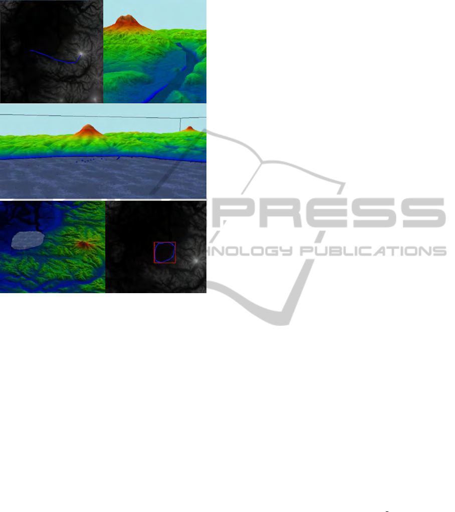
Figure 2: A river (top) and lake (center and bottom) added
to a high-resolution terrain using 2D sketch input.
mental updates to the terrain at run-time in order
to enable interactive editing of large terrains. The
update regions can be of arbitrary size making the
technique suitable for applications requiring constant
small changes, such as sketching a river, and for large
changes, such as inserting a new mountain range. We
extended the underlying Geometry Clipmap approach
to allow arbitrary view points, including a birds-eye
perspective, which is useful for terrain editing.
Our results demonstrate that terrains can be edited
and rendered at interactive frame rates in high res-
olutions. The main limitation is the maximum al-
lowed terrain size due to compiler restrictions and
GPU memory limitations. This could be overcome by
employing concepts from out-of-core terrain render-
ing techniques. Additional future work includes the
use of 2D textures, including multi-texturing in order
to combine large-scale texture variations with terrain
details.
REFERENCES
Asirvatham, A. and Hoppe, H. (2005). Terrain rendering
using GPU-based geometry clipmaps. GPU Gems,
2:27–46.
Atlan, S. and Garland, M. (2006). Interactive multiresolu-
tion editing and display of large terrains. Computer
Graphics Forum, 25(2):211–223.
Bhattacharjee, S., Patidar, S., and Narayanan, P. (2008).
Real-Time Rendering and Manipulation of Large Ter-
rains. In Computer Vision, Graphics & Image Process,
2008. ICVGIP’08, pages 551–559.
Dan, L., Yingsong, H., M., D., and Xun, L. (2009). The Re-
search and Implementation of Interactive Terrain Edit-
ing and Crack Elimination. In Proc. of Computational
Intelligence and Software Engineering (CiSE 2009),
pages 1–4.
de Boer, W. (2000). Fast terrain rendering using geometri-
cal mipmapping. http:// www.flipcode.com/ articles/
articlegeomipmaps.pdf.
Duchaineau, M., Wolinsky, M., Sigeti, D., Miller, M.,
Aldrich, C., and Mineev-Weinstein, M. (1997).
ROAMing terrain: real-time optimally adapting
meshes. In Proceedings of Visualization ’97, page 88.
He, Y., Cremer, J., and Papelis, Y. E. (2002). Real-time
extendible-resolution display of on-line dynamic ter-
rain. In Proc. of Graphics Interface, pages 151–160.
Keymer, D., Wuensche, B., and Amor, R. (2009). Virtual
Reality User Interfaces for the Effective Exploration
and Presentation of Archaeological Sites. In Proc. of
CONVR, pages 139–148.
Lindstrom, P., Koller, D., Hodges, L., Ribarsky, W., Faust,
N., and Turner, G. (1995). Level-of-detail manage-
ment for real-time rendering of phototextured terrain.
Graphics, Visualization & Usability Center, Georgia
Institute of Technology, Technical Report GITGVU-
95-06.
Losasso, F. and Hoppe, H. (2004). Geometry clipmaps: ter-
rain rendering using nested regular grids. In Proc. of
SIGGRAPH 2004, pages 769–776.
Pajarola, R. and Gobbetti, E. (2007). Survey of semi-regular
multiresolution models for interactive terrain render-
ing. The Visual Computer, 23(8):583–605.
Schneider, J. and Westermann, R. (2006). GPU-friendly
high-quality terrain rendering. Journal of WSCG,
14(1-3):49–56.
van den Hurk, S., Yuen, W., and W
¨
unsche, B. C. (2011).
Real-time terrain rendering with incremental load-
ing for interactive terrain modelling. Graphics
group technical report #2011-003, Department
of Computer Science, University of Auckland.
http://www.cs.auckland.ac.nz/∼burkhard/Reports/
GraphicsGroupTechnicalReport2011
003.pdf.
GRAPP 2011 - International Conference on Computer Graphics Theory and Applications
186
