
REAL-TIME IMAGE BASED VISUAL SERVOING ARCHITECTURE
FOR MANIPULATOR ROBOTS
Adrian Burlacu, Copot Cosmin, Andrei Panainte, Carlos Pascal and Corneliu Lazar
Department of Automatic Control and Applied Informatics, ”Gheorghe Asachi” Technical University of Iasi, Iasi, Romania
Keywords:
Visual servoing, Real-time implementation, Feature points, Manipulator robot.
Abstract:
The necessity of designing flexible and versatile systems is one of the most current trends in robotic research.
Including visual servoing techniques in an existing robotic system is a very challenging task. In this paper a
solution for extending the capabilities of a 6 d.o.f manipulator robot, for visual servoing system development,
is presented. An image-based control architecture is designed and a real-time implementation on an ABB
robot is developed. The image acquisition and processing, toghether with the computing of the image-based
control law were implemented in Matlab. A new type of robot driving interface that links the robots’ controller
with Matlab environment is proposed. The robustness and stability of the feature point based control laws are
tested in multiple experiments. Experimental results revealed very good performances for the real-time visual
servoing system.
1 INTRODUCTION
Visual servoing has been studied in various forms for
more than three decades starting from simple pick
and place tasks to todays real-time, advanced ma-
nipulation of objects. In terms of manipulation, one
of the main motivations for incorporating vision in
the control loop was the demand for increased flex-
ibility of robotic systems. The main aim of the
image based visual servoing is to control the end-
effector of a robot arm such as a set of image features
to reach a desired configuration (Hutchinson et al.,
1996; Chaumette and Hutchinson, 2007). Even if
new visual features were proposed (Marchand and
Chaumette, 2005; Chaumette and Hutchinson, 2006),
point features still remain the most used image mea-
surements in designing real-time visual servo control
laws. Usually they are coordinates of the centroids or
corners that describe an object.
The main problem for visual servoing systems is
that in order to have a robust and stable control law
the image based controller must be designed taking
into account the dynamic constraints of the manipula-
tor robot and also the workspace configuration. A di-
rect implementation of the visual feedback scheme is
very difficult to obtain, mainly due to the access im-
possibility over the low level components (ex: joint
motors) that are part of the robot. Due to this imped-
iment, a method for extending the capabilities of the
robots’ controller is needed. This extension must be
designed in a matter that all the existing time periods
(due to communication, to image processing and con-
trol computation) are included and the system works
in real-time.
Many simulators that implement image based vi-
sual servoing architectures were proposed in the last
decade (Corke, 2005; Cervera, 2003; Lazar and
Burlacu, 2008). Also, real time applications of visual
servoing systems are presented in different research
areas. A real-time 3D visual tracking and control al-
gorithm for a 5 degrees of freedom microassembly
workcell is presented in (Tamadazte et al., 2009). The
solution proposed uses a model-based tracking algo-
rithm in real-time in order to obtain the 3D pose of
the Micro Electro Mechanical Systems. A classical
Reinforcement Learning (RL) architecture that use an
actor-critic design was proposed for a real-time visual
tracking task of a 6 d.o.f. robot (Perez-Cisneros and
Mora-Galvez, 2005). Knowing, the potential of ul-
trasound imaging for guiding a surgical instruments,
Stoll (Stoll et al., 2006) proposed a real-time 3D ultra-
sound image-guide robotic system. This system was
designed in order to autonomously navigate a mini-
mally invasive surgical instrument in 6 d.o.f. using
only passive tracking.
In the present paper a real time image based vi-
sual servoing architecture for a 6 d.o.f. manipulator is
proposed. The architecture is structured in three mod-
502
Burlacu A., Cosmin C., Panainte A., Pascal C. and Lazar C..
REAL-TIME IMAGE BASED VISUAL SERVOING ARCHITECTURE FOR MANIPULATOR ROBOTS.
DOI: 10.5220/0003367005020510
In Proceedings of the International Conference on Computer Vision Theory and Applications (VISAPP-2011), pages 502-510
ISBN: 978-989-8425-47-8
Copyright
c
2011 SCITEPRESS (Science and Technology Publications, Lda.)

ules (Image Based Control, Robot Driver Interface,
Robot Controller), each one having a different objec-
tive, but in the same time is connected with the other
ones. The configuration of the manipulator robot is
an eye-in-hand type. Images are acquired and pro-
cessed in real time, thus point features are extracted.
The visual feedback control law will be designed in
order to minimize the error between the current and
the desired point features. A 6 d.o.f. ABB IRB-
2400 manipulator robot was chosen in order to imple-
ment the designed visual servoing architecture. On
the robots’ gripper a video camera was mounted. A
commonly cited problem in real-time applications is
the bounded bandwidth communication between the
visual sensor and the robot which induce a latency in
the closed-loop system. In order to obtain a sufficient
sampling bandwidth an extension of the robots’ con-
troller (named ABB S4CPlus) is usually a solution.
In (Blomdell et al., 2005) such an extension was de-
veloped, but the visual servoing applications were not
considered. A new extension of the capabilities of
the ABB S4CPlus controller is proposed in this pa-
per. Using a robot driver interface, low-level real time
interaction between the robot controller and a mas-
ter PC are possible. The visual control algorithm was
implemented in Matlab using a classical proportional
approach based on point features.
The present paper is organized as follows: Section
II presents the structure of a visual servoing system
for a real-time application. Section III is dedicated
to the image based control algorithm. In Section IV
experimental results are presented, while the conclu-
sions are detailed in Section V.
2 VISUAL SERVOING
ARCHITECTURE
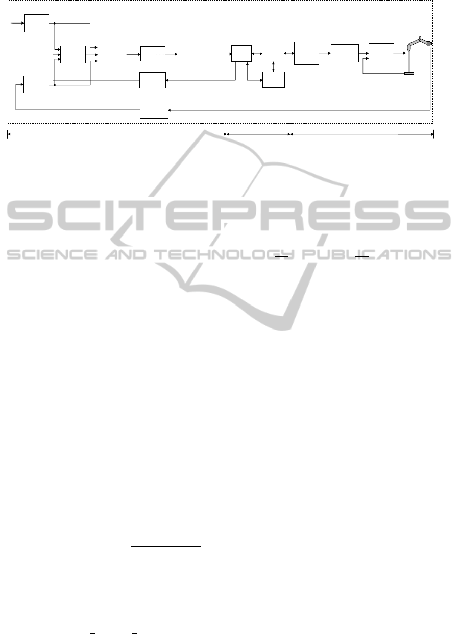
In order to develop a real-time image based control al-
gorithm for an ABB manipulator robot with 6 d.o.f.,
using point features, the visual servoing control ar-
chitecture from Figure1 was designed. The proposed
structure has as input the desired configuration f
∗
of
the point features extracted from the desired image.
Starting from an initial pose of the gripper, an im-
age is acquired using a Sony XCD-V60CR camera
mounted on the gripper and point features f were ex-
tracted based on the Harris detector presented in the
next Section. The image based controller minimizes
the error between the desired f
∗
and the current point
features f (t), and has as output the reference cam-
era velocity v
∗
c
. Integrating this reference camera ve-
locity a new gripper pose denoted x
∗
c
is obtained and
transformed into a quaternion based pose representa-
tion (x
∗
c
q
) which represents the input for the robot con-
troller via the Robot Driver Interface (RDI).
This architecture is composed from three different
modules: Image Based Control, RDI and Robot Con-
troller, each one having a different execution time.
The following notions are considered: T
ap
the exe-
cution time for the Image Based Control module, T
c
the RDI module execution time and T the execution
time for Robot Controller module. The sample period
(T
s
) of the entire architecture is obtained from:
T
s
= T
ap
+ T
c
+ T. (1)
The Image Based Control module implements an im-
age based control algorithm and contains the follow-
ing blocks: Features Extraction, Interaction Matrix,
Proportional Controller, Integrator, Quaternion based
Pose Representation, Depth Extraction and Image
Acquisition. Features Extraction, Interaction Matrix
and Proportional Controller blocks will be presented
in the next Section, while Image Acquisition block
is detailed in the Experimental Results section. The
RDI module has three blocks: I/O, Robot Interface
and User Interface. Robot Controller (ABB S4CPlus)
is a module composed from all the entities that en-
sure the correct motion of the robot. ABB S4CPlus
controller uses instructions from the RAPID program
in order to generate trajectories for the internal arm-
level. Next, the motor controllers are responsible for
the low-level motion control of each joint. In this Sec-
tion the Rapid Program block of the Robot Controller
module and the RDI module are detailed.
2.1 Rapid Program
ABB IRB 2400 is a 6-axis manipulator robot, de-
signed specifically for manufacturing industries that
use flexible robot-based automation. The robot is
equipped with an operating system called BaseWare
OS that constitutes the kernel of the RobotWare fam-
ily.
BaseWare OS controls every aspect of the robot,
like motion control, development and execution of ap-
plication programs communication, etc. The proper-
ties of BaseWare OS can be split up in five main ar-
eas: The RAPID Language and Environment; Excep-
tion handling; Motion Control; Safety; the I/O Sys-
tem. RAPID is a textual programming language for
industrial ABB robots, thus the RAPID program can
be written using the console (teach pendant) and also,
it can be written on any other computer following the
RAPID syntax.
The motion of the robot represents the pose mod-
ification of a frame attached to the gripper. The ori-
gin of the gripper’s reference frame is known as Tool
REAL-TIME IMAGE BASED VISUAL SERVOING ARCHITECTURE FOR MANIPULATOR ROBOTS
503
User
Interface
( )
f t
f
∗
Trajectory
Generation
Features
Extraction
Image
Acquisition
Features
Extraction
( )
t
∗
c
v
( )
t
∗
c
x
Motor
Controller
f
L
Proportional
Controller
Integrator
I/O
Robot
Interface
Depth
Extraction
Rapid
Program
( )
z t
Desired
Image
Interaction
Matrix
( )
t
∗
q
c
x
ROBOT DRIVER
INTERFACE
ROBOT CONTROLLER
Quaternion
based Pose
Representation
IMAGE BASED CONTROL
ap
T
c
T
T
Figure 1: Visual servoing structure.
Center Point (TCP). The structure of any variable that
stores a pose of the TCP is:
pPosDest = [[x
1
,x
2
,x
3
],[q
0
,q
1
,q
2
,q
3
],...], (2)
where [x
1
,x
2
,x
3
] represent the new position of the
TCP and [q
0
,q
1
,q
2
,q
3
] are the TCP orientation given
in quaternion.
Integrating the reference camera velocity v
∗
c
=
[v
∗
x
,v
∗
y
,v
∗
z
,ω
∗
x
,ω
∗
y
,ω
∗
z
]
T
, the new TCP pose x
∗
c
=
[x
1
,x
2
,x
3
,α,β,γ]
T
is obtained. The new orientation
is stored in a roll-pitch-yaw (RPY) matrix:
R =
"
c(α)c(β) c(α)s(β)s(γ)−s(α)c(γ) c(α)s(β)c(γ)+s(α)s(γ)
s(α)c(β) s(α)s(β)s(γ)+c(α)c(γ) s(α)s(β)c(γ)−c(α)s(γ)
−s(β) c(β)s(γ) c(β)c(γ)
#
, (3)
where c() and s() denotes the cos and sin functions.
In case of ABB IRB-2400 robots, as for many
manipulator robots, the orientation is represented by
quaternions (Siciliano et al., 2009). In the same way
as complex numbers, the quaternions can be defined
by introducing abstract symbols i, j,k which satisfy
the rules i
2
= j
2
= k
2
= i jk = −1 and the usual al-
gebraic rules except the commutative law of multipli-
cation. When quaternions are used in geometry, it is
more convenient to define them as:
ˆq = q
0
+~q = q
0
+ q
1
i + q
2
j + q
3
k, (4)
where the imaginary part q
1
i + q
2
j + q
3
k behaves like
a vector ~q = (q
1
,q
2
,q
3
) in V
3
, and the real part q
0
behaves like a scalar in R. The conjugate of a quater-
nion is denoted ˆq
∗
= q
0
−~q. Let Q
u
be the ensemble of
quaternions having unit length (
q
q
2
0
+ q
2
1
+ q
2
2
+ q
2
3
=
1). If ˆq ∈ Q
u
then rotating a vector
−→
r around an
−→
η
direction axis with an angle α can be express by:
ˆ
ρ = ˆq ˆr ˆq
∗
, (5)
where is the quaternion multiplication, ˆr = 0 +
−→
r ,
ˆ
ρ = 0 +
−→
ρ and ˆq = cos
α
2
+
−→
η sin
α
2
.
The transformation that links the orientation ex-
pressed by a rotation matrix with the orientation ex-
pressed by quaternions is:
q
0
= ±
1
2
p
1 + r
11
− r
22
− r
33
; q
1
=
1
4q
0
(r
12
+ r
21
)
q
2
=
1
4q
0
(r
13
+ r
31
); q
3
=
1
4q
0
(r
32
− r
23
),
(6)
where r
i j
are the components of the rotation matrix
from (3). Equation (6) will be used to convert the
RPY matrix in quaternion that is necessary to control
the gripper of the ABB IRB-2400 manipulator robot.
The pPosDest variable which store the TCP pose
is called RobTarget and represent the input signal for
the ABB S4CPlus controller. Moving to a RobTarget
data involves using one of the following instruction:
MoveAbsJ, MoveC, MoveJ, MoveL, MoveCDO,
MoveJDO, MoveLDO, MoveCSync, MoveJSync. In
order, to control the griper movements of an ABB
IRB-2400 manipulator robot a MoveJ instruction is
used and has the following syntax:
MoveJ ToPoint Speed[\V ][\T ] Zone[\Z] Tool[\Wob j]
with ToPoint - the desired point, Speed - the TCP
speed, Zone - the TCP position related to desired
point and Tool - the effector used. The optimal pa-
rameter [\V ] represent the TCP velocity in mm/s and
replace the Speed argument, [\T ] is the execution
time for a motion from the current to the new TCP
pose, [\Z] specified the distance of the effector ap-
proaches the target position and [\Wob j] represent the
working object.
The new reference pose of the robots’ TCP, rep-
resenting the output of the image based visual con-
trol algorithm after integration, is saved in a file and
transmitted to the robots’ controller. The first row of
the file contains the position given in Cartesian coor-
dinates and the second line from the file contains the
VISAPP 2011 - International Conference on Computer Vision Theory and Applications
504
orientation as quaternion form. Workflow begins with
a first step by copying the RAPID program from the
disk and loading it on the S4CPlus controller. This
simple program is designed using a single persistence
variable pPosDest. The RAPID program is formed by
lines of code that have as effect the movement of the
griper to the pose defined by the position and orien-
tation contained in variable pPosDest. The procedure
that performs this operation is decribed below:
PROCMoveTo()
checkPoint := 0;
Con f J \ O f f ;
Con f lict \ O f f ;
MoveJ pPosDest, T 0.5, fine, toolGRIP;
Con f J \ On;
Con f lict \ On;
checkPoint := −1;
ENDPROC
This procedure is loaded in the Robot Controller
and executed when the persistent variable pPosDest
is changed by the image-based control algorithm.
2.2 Robot Driver Interface
In order to have a direct communication between the
Matlab environment and the robots’ controller a new
type of Robot Driver Interface (RDI) is proposed. The
RDI is the link between the MATLAB application
which implements the Image Based Control module
and the Rapid Program (RP). The role of RDI is to
analyze the MATLAB output and transfer the proper
data to the RP by running a specific procedure of the
RP, and to return the new pose of the TCP to the MAT-
LAB program. The RDI incorporates the Robot In-
terface module, the I/O module, and a User Interface
module.
The Robot Interface module manages the commu-
nication between the RDI and the S4Plus Controller,
which is the robots controller. This one allows exter-
nal interaction through the TCP/IP via two serial con-
nections (RS232 and RS422 Full duplex) or an Ether-
net network. The effective communication is carried
out by the ABB Interlink service, which sends com-
mands to the robots controller, collects data from it
through the Interlink Monitor module of the service
by means of a polling mechanism and modifies the
RP at the persistent variables level. It is important
to note that the minimum polling interval that can be
set is 200 ms, and this interval is also maintained be-
tween two successive commands. For a given list of
persistent variables, the Interlink Monitor maintains
their state and notifies each time when a value was
changed. A programmable way to interact with the
Interlink service and Monitor is allowed through a
specific ActiveX component, namely the Helper Con-
trol, part of WebWare SDK (Cederberg et al., 2002).
The Robot Interface module wraps the components
and offers further means to the other modules.
1
2
3
4
5
6
7
8
9
10
Figure 2: User Interface.
The role of the I/O module is to acquire the MAT-
LAB output, to read the new pose of the TCP and
to send it towards the MATLAB input. When the
file is changed, it interprets this as a command and
reads the file information, modifies the persistent vari-
ables in the RP (in this case the pPosDest variable see
the previous section) and runs the proper procedure
(MoveTo) using the robot interface module. The end
of the procedure is notified by the monitored variable
checkPoint and its value is changed to -1. After this,
the I/O module gets the current pose of the gripper
and puts the information at the MATLAB input.
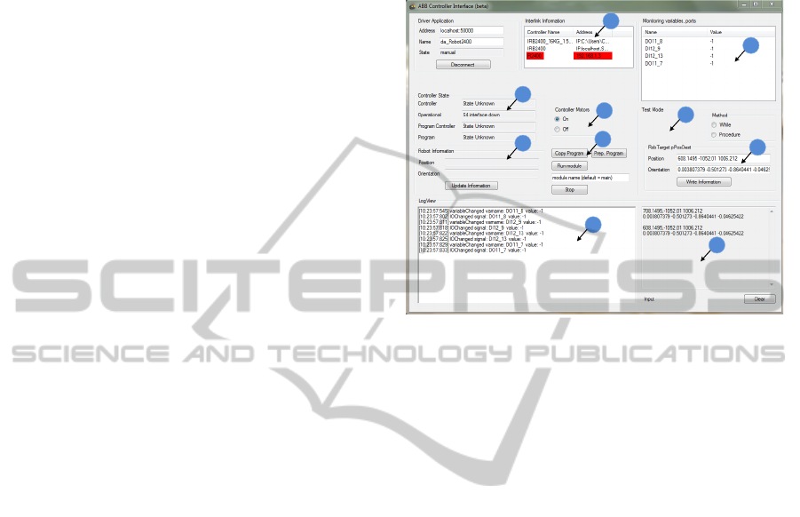
The User Interface of the RDI (Figure 2) was de-
signed, tested and implemented in C# and has the fol-
lowing capabilities: connects the RDI to a robot con-
troller (label 1), interacts with the selected controller
by copying, running, stopping Rapid programs (label
4), open/close the robots motors (label 3), and change
its grippers position/orientation (label 10). Addi-
tionally, it maintains and shows relevant information
about the controller and robots states (labels 2 and 7),
the program variables (6), significant events (8), and
also the data from the MATLAB output (9).
Using these modules, the RDI offers a solution to
link the MATLAB algorithm to the physical compo-
nent. From the safety point of view, the solution mod-
ifies safely some persistent variables and guides the
work-flow of the Rapid program. As performance,
our measurement showed that the time between a
command from visual control algorithm and the effec-
tive execution by the robot controller is in the polling
interval set at 200 ms. Through RDI module, the cur-
REAL-TIME IMAGE BASED VISUAL SERVOING ARCHITECTURE FOR MANIPULATOR ROBOTS
505

rent gripper pose are used as feedback in order to ob-
tain a better approximation of the depth related to the
camera frame, depth that are used in visual control
algorithm to compute the interaction matrix.
3 IMAGE BASED VISUAL
CONTROL
In this Section the image based control algorithm is
presented. As visual information input point fea-
tures are considered. Next an algorithm for point
features extraction from monocrome images is pre-
sented. Also the design of the visual proportional con-
troller is revealed. The proposed controller minimizes
the error between current and desired point features
configuration, while taking into account the visibility
constraints, and generates the reference velocity vec-
tor of the camera.
3.1 Point Features
A variety of operators have been proposed to detect
point features. For our real-time visual servoing struc-
ture the Harris detector (Ma et al., 2003) was chosen.
For the Harris algorithm, the definition of a point fea-
ture is typically taken to be a location in the image
where the local autocorrelation function has a distinct
peak.
Given an image I(u,v), the autocorrelation matrix
is computed from:
A =
∑
u
∑
v
g(u,v)
I
2
u
I
u
I
v
I
u
I
v
I
2
v
=
< I
2
u
> < I
u
I
v
>
< I
u
I
v
> < I
2
v
>
, (7)
where g is the gaussian kernel and I
u
,I
v
are the gradi-
ents on the u and v directions:
I
u
=
∂I
∂u
= I ∗ [−1 0 1]
I
v
=
∂I
∂v
= I ∗ [−1 0 1]
T
. (8)
The main idea for detecting point features is to
analyze the function:
C(A) = det(A) − δtrace
2
(A), (9)
where δ ∈ R is a tunable sensitivity parameter. In or-
der to establish the influence of δ let the two eigenval-
ues (which in this particular case are also the singular
values) of A be σ
1
, σ
2
. Then:
C(A) = σ
1
σ
2
− δ(σ
1
+ σ
2
)
2
, (10)
and for δ being small, both eigenvalues need to be big
enough to make C(A) pass a threshold thus only point
features are detected.
The algorithm has proved robust due to its high re-
liability in finding L-junctions and its good temporal
stability making it an attractive point feature detec-
tor for tracking. Also the computational time is lower
than 0.15 ms thus being suitable for real time imple-
mentation.
3.2 Visual Proportional Controller
The main goal of any image based control architecture
(IBVS) is to drive a robot system using information
acquired by a visual sensor (Chaumette and Hutchin-
son, 2006). If the considered robot system is a manip-
ulator robot that has a video camera mounted on the
gripper then a visual servoing structure with an eye-
in-hand configuration is created. In order to achieve
the main goal, a trajectory for the video camera must
be designed. The trajectory is given by the integra-
tion of the camera velocity obtained from the IBVS
architecture by minimizing the error between the cur-
rent point features configuration and the desiring one.
The error between point features in the image plane is
defined as follows:
e(t) = f (t) − f
∗
, (11)
where f (t) represents the point features position at
time t and f
∗
the desired configuration. Equation (11)
is the general representation of the input signal for
the image based controller. The outputs of the im-
age based controller is the reference velocity v
∗
c
of the
camera. If the task of extracting point features and
finding the correspondences in the desired configu-
ration is completed then a relationship between time
variation of f (t) and camera velocity can be gener-
ated. Let v
∗
c
be a vector composed from linear veloci-
ties of the camera frame and the instantaneous angular
velocities of the camera frame.
The link between the motion of point features and
camera velocity is given by (Chaumette and Hutchin-
son, 2006):
˙
f = Lv
∗
c
, (12)
where by L ∈ R
2n×6
is denoted the image Jacobian of
n point features that compose the vector f . From (11)
and (12) it is obvious that:
˙e = Lv
∗
c
. (13)
In order to increase the robustness of the visual
based control algorithm a different error function can
be used:
e
D
= De, (14)
VISAPP 2011 - International Conference on Computer Vision Theory and Applications
506
where D = Diag{d
1
,...,d
n
} is a weighting matrix
used to remove the outliers from the point features
set. The weights d
i
vary from 1 when the robust es-
timation gives full confidence and 0 when the feature
is doubstlessly an outlier. For exemple an weighting
algorithm for establishing the values for {d
1
,...,d
n
}
can be generated using the distance of each feature to-
wards the center of the image. If the i-th point feature
is positioned near the image center, the d
i
will have a
value close to 1, else if the point feature is near one
the edges of the image the value of d
i
will be close to
0. Taking into acount that D can be considered to vary
slowly and thus
˙e
D
= D ˙e. (15)
A classical proportional controller is defined by
(Chaumette and Hutchinson, 2006):
v
c
∗
= −λ
c
L
+
e
D
, (16)
but using (13), (14), (15) a more robust expression can
be obtained:
v
c
∗
= −λ
\
(DL)
+
De. (17)
Let
L
f
= DL, (18)
be the interaction matrix of the detected point features
and thus (17) can be expressed:
v
c
∗
= −λL
+
f
De. (19)
In (19) L
+
f
∈ R
6×2n
is the Moore-Penrose pseu-
doinverse of L
f
, that is L
+
f
= (L
T
f
L
f
)
−1
L
T
f
. Consider-
ing that the structure of a point feature is f = (u, v) =
K · [x,y,1]
T
, where K is the intrinsic parameters ma-
trix (Ma et al., 2003),(u,v) are the image plane coor-
dinates expressed in pixels, (x,y) the point features’
coordinate in the virtual projection plane, then the in-
teraction matrix for a point feature can be computed
using (Mansard et al., 2009):
L
1
f
=
h
d
1
0
0 d
2
i
·
−
1
z
0
x
z
xy −(1+y
2
) y
0
1
z
y
z
1+y
2
−x·y −x
, (20)
where z is the depth of the corresponding projection
point in the Cartesian space related to the camera
frame. The initial depths of the point features are re-
covered using an epipolar geometry method (Hartley
and Zisserman, 2004), were the two views are the ini-
tial image and the desired one.
The correspondence between the point features
detecting in consecutive frames is a computational
consuming operation. In order to have a real time im-
plementation this operation must be optimized. Our
approach was to use a local model predictor of the fu-
ture position of the point feature in order to narrow
the correspondence search area. If f (t) is the current
position of the point feature then the correspondent
f (t + T
s
) from the next frame will be search in the
proximity of the predicted position computed by the
discretization of (12) using Euler’s method (Lazar and
Burlacu, 2009):
˜
f (t + T
s
) = f (t) + T
s
L
f
v
∗
c
(t). (21)
Due to the composition of T
s
from (1) the velocity
vector v
∗
c
is equal to 0 during the period T
ap
+ T
c
. An
area of 11×11 pixels centered in
˜
f (t +T
s
) is extracted
from the image and the point feature detector is em-
ployed, thus resulting the correspondent f (t + T
s
).
4 EXPERIMENTAL RESULTS
The visual servoing architecture proposed in the
present paper was implemented, tested and validated,
and the results of the conducted experiments are re-
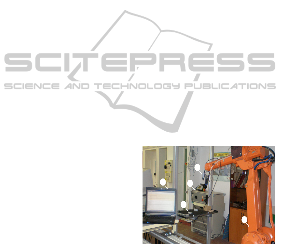
vealed. A visual servoing system (Figure 3) was de-
veloped and it is composed from: a master PC (la-
bel 1), the S4CPlus ABB controller (label 2), an IRB
2400 ABB 6 d.o.f. manipulator robot (label 3), a vi-
sual sensor mounted on the gripper (label 4) and the
work table (label 5). The link between the visual sen-
sor (label 4) and the master PC (label 1) is realized by
an IEEE-1394b serial bus interface. The robots’ con-
troller (label 2) communication with the mater PC is
realized using an Ethernet network.
1
4
2
3
5
Figure 3: Servoing system.
Images were acquired using a Sony XCD-V60CR
visual sensor. This type of industrial camera is
based on a serial communication interface IEEE-
1394b (FireWire). The IEEE-1394b interface allows a
transfer rate of 800 Mbit/s and use a 9-pin connector.
The intrinsic camera parameters used are : the unit
cell size 7.4µm × 7.4µm, the depth resolution was set
to RAW16: 10bits/pixel and the focal length was set
REAL-TIME IMAGE BASED VISUAL SERVOING ARCHITECTURE FOR MANIPULATOR ROBOTS
507
to 4.5mm. Since an eye-in-hand camera configuration
it is used, the extrinsic camera parameters are related
to the robot effector frame. The visual sensor is able
to acquire 90 fps with 640 × 480 image resolution. In
order to optimize the computational time for the point
features extraction, images with 320 × 240 resolution
were considered.
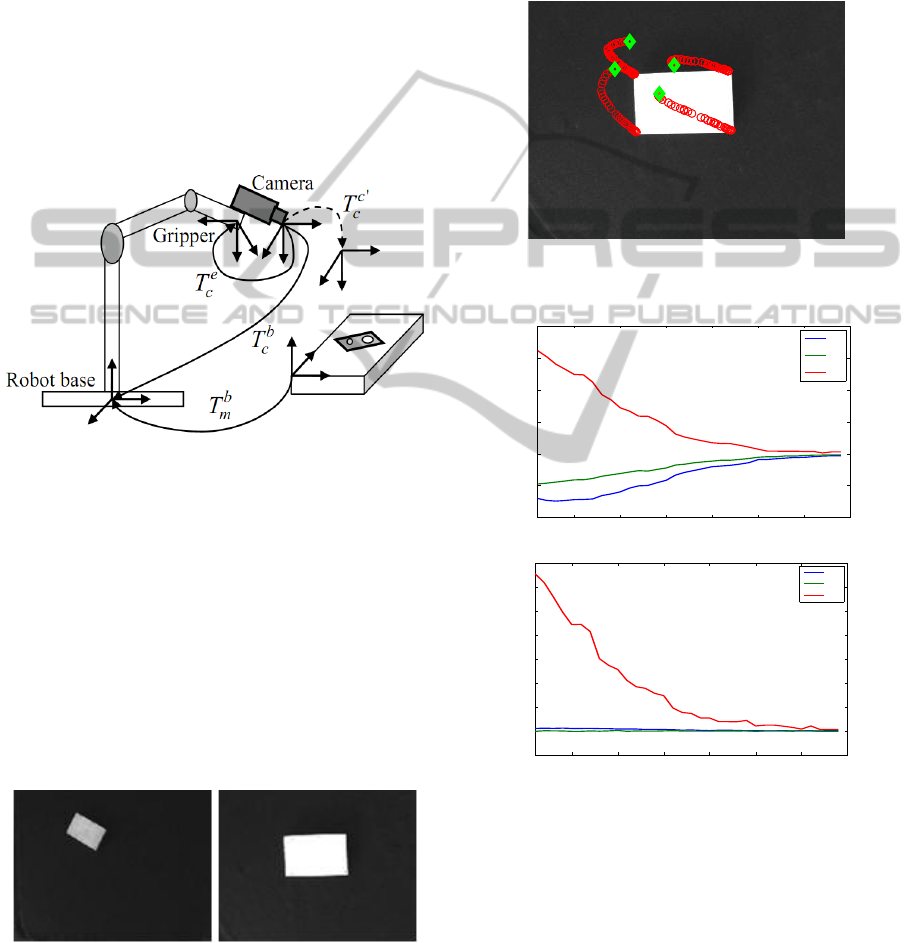
Considering the frames attached to the robot base
R
b
, to the camera R
c
, to the gripper R
e
and the work
table R
m
, the homogeneous matrix T
b
m
between the
frames R
m
and R
b
is given (Figure 4). Having an eye-
in-hand camera configuration and knowing the trans-
formation T
e
c
between R
c
and R
e
frames, thus, the
homogeneus transformation T
b
c
between the frames
R
c
and R
b
is obtained. Let T
c
0
c
be the homogeneus
Work table
Figure 4: Robot frames.
transformation between R
c
frame and the new cam-
era pose. The following work scene information were
apriori known: the pose of the robot frame, the pose
of the object frame, the transformation between cam-
era and TCP.
Considering an initial and desired image (Figure
5), point features were extracted using the Harris de-
tector. First step was to establish the correspondence
between the initial and the desired point features. This
step is done, for now, manually by the user. After the
starting correspondence will be generated automati-
cally using the motion prediction model (21).
Figure 5: Initial and desired images.
Having established the correspondence for each
iteration, the image based control law (19) was im-
plemented in order to ensure an exponential decrease
of the error from the image plane. The proportional
controller was tuning manually and the parameter λ
was set to 0.01. For this visual feedback control law
and with an execution time for motion T = 0.5, the
following results are obtained: the point features tra-
jectory in image plane (Figure 6), the camera velocity
vector (Figure 7) and the camera trajectory in Carte-
sian space (Figure 8).
Figure 6: Image plane point features trajectory for λ = 0.01
and T = 0.5.
1 5 10 15 20 25 30 35
−100
−50
0
50
100
150
200
Samples
Linear velocities (mm/s)
v
∗
x
v
∗
y
v
∗
z
1 5 10 15 20 25 30 35
−0.1
0
0.1
0.2
0.3
0.4
0.5
0.6
0.7
Samples
Angular velocities (rad/s)
ω
∗
x
ω
∗
y
ω
∗
z
Figure 7: Linear an angular camera velocities evolution.
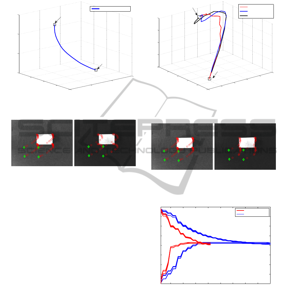
The visual servoing system performances depends
on the gain factor λ and on the execution time for the
motion parameter T . Considering a new starting con-
figuration (the green diamond from Figure 9), a gain
factor λ = 0.01 and an execution time raging from
0.5 to 0.9, the following point features trajectory is
obtained, Figure 9. As it can be observed, if the exe-
cution time is increased, the error will decrease faster
but with a more complicated gripper trajectory (Fig-
ure 10) and a greater effort for controlling the robot
VISAPP 2011 - International Conference on Computer Vision Theory and Applications
508
650
700
750
800
−1180
−1160
−1140
−1120
900
950
1000
1050
X (cm)
Y (cm)
Z (cm)
3D camera trajectory
Initial position
Final position
Figure 8: 3D Camera trajectory for λ = 0.01 and T = 0.5.
(a) (b)
Figure 9: Point features trajectory for: (a) λ = 0.01 and
T = 0.5; (b) λ = 0.01 and T = 0.9.
joints.
Considering the same initial configuration, a new
experiment was conducted in order to analyze the
visual servoing system performances related to gain
factor changes. Thus, for a constant execution time
T = 0.5, different values for the gain factor was con-
sidered: λ = 0.01 and λ = 0.02. In Figure 11, the
image plane trajectory of the point features are il-
lustrated. Analyzing the error evolution (Figure 12)
it can be observed that, increasing the gain factor
will leads to a faster decrease of the error and con-
sequently a decrease of the transient response. The
downward when increasing the gain factor is the in-
crease of the control effort, undesirable action in a
control structure. Therefore, it is necessary to estab-
lish a compromise value for the gain factor in order to
obtain optimal performances without great effort.
5 CONCLUSIONS
In the present paper, a real-time image based visual
servoing architecture for an ABB manipulator robot
with 6 d.o.f. and an eye-in-hand configuration was de-
veloped. The proposed architecture is composed from
640
650
660
670
680
690
−1260
−1240
−1220
−1200
−1180
−1160
934
936
938
940
942
X (cm)
Y (cm)
Z (cm)
λ=0.01 and T=0.5
λ=0.01 and T=0.7
λ=0.01 and T=0.9
Initial position
Final position
Figure 10: 3D Camera trajectory for different execution
motion time and λ = 0.01.
(a) (b)
Figure 11: Image plane point features trajectory for: (a)
T = 0.5 and λ = 0.01; (b)T = 0.5 and λ = 0.02.
1 5 10 15 20 25 30 35 40 45
−80
−60
−40
−20
0
20
40
60
80
Samples
Error (pixels)
λ=0.02 and T=0.5
λ=0.01 and T=0.5
Figure 12: Point features error evolution for different gain
parameter.
three modules (Image Based Control, Robot Driver
Interface and Robot Controller) connected between
them, but each one has a different objective.
The communication between the robots’ con-
troller and the Matlab environment which implements
the Image Based Control module is realized using a
new extension of the robot controller based on RDI.
In order to implement the designed visual servoing ar-
REAL-TIME IMAGE BASED VISUAL SERVOING ARCHITECTURE FOR MANIPULATOR ROBOTS
509

chitecture, a classical proportional control law based
on point features was considered. For a better sta-
bility of the control law, the RDI provide a feedback
(the current gripper pose) that are used to estimate the
depths of the point features, thus generated the inter-
action matrix. The experimental results revealed good
robustness and stability for the real-time image based
servoing architecture designed.
ACKNOWLEDGEMENTS
This paper was supported by the project PERFORM-
ERA ”Postdoctoral Performance for Integration in the
European Research Area” (ID-57649), financed by
the European Social Fund and the Romanian Govern-
ment.
REFERENCES
Blomdell, A., Bolmsj, G., Brogrdh, T., Cederberg, P., Isaks-
son, M., Johansson, R., Haage, M., Nilsson, K., Ols-
son, M., Olsson, T., Robertsson, A., and Wang, J.
(2005). Extending an industrial robot controllerim-
plementation and applications of a fast open sensor
interface. IEEE Robotics and Automation Magazine,
12(3):85–94.
Cederberg, P., Olsson, M., and Bolmsj, G. (2002). Remote
control of a standard abb robot system in real time
using the robot application protocol (rap). In Pro-
ceedings of the International Symposium on Robotics,
ISR2002, Stockholm.
Cervera, E. (2003). Visual servoing toolbox.
http://vstoolbox.sourceforge.net/. Jaume I Uni-
versity.
Chaumette, F. and Hutchinson, S. (2006). Visual servo con-
trol, part i: Basic approaches. IEEE Robotics and Au-
tomation Magazine, 13(4):82–90.
Chaumette, F. and Hutchinson, S. (2007). Visual servo con-
trol, part ii: Advanced approaches. IEEE Robotics and
Automation Magazine, 14(1):109–118.
Corke, P. (2005). Machine vision toolbox. IEEE Robotics
and Automation Magazine, 12(4):16–25.
Hartley, R. and Zisserman, A. (2004). Multiple View Geom-
etry in Computer Vision. Cambridge University Press,
2 edition.
Hutchinson, S., Hagerand, C., and Corke, P. (1996). A tuto-
rial on visual servo control. IEEE Trans. On Robotics
and Automation, 12(5):651–670.
Lazar, C. and Burlacu, A. (2008). Dynamic simulation
model for image based visual servo control systems.
In 11th Int. Conf. on Optimization of Electrical and
Electronic Equipment. OPTIM 2008., pages 185–190,
Brasov, Romania.
Lazar, C. and Burlacu, A. (2009). Visual servoing of robot
manipulators using model-based predictive control.
In 7th IEEE International Conference on Industrial
Informatics. INDIN 2009., pages 690–695, Cardiff,
Wales.
Ma, Y., Soatto, S., Kosecka, J., and Sastry, S. (2003). An
Invitation to 3-D Vision. Springer.
Mansard, N., Remazeilles, A., and Chaumette, F. (2009).
Continuity of varying-feature-set control laws. IEEE
Trans. on Automatic Control, 54(11):2493–2505.
Marchand, E. and Chaumette, F. (2005). Feature track-
ing for visual servoing purposes. Robotics and Au-
tonomous Systems, 52(1):53–70.
Perez-Cisneros, M. and Mora-Galvez, A. (2005). Real-time
robotic visual servoing using reinforcement learning
agents. In Proceedings of the IEEE International Con-
ference on Information and Automation, pages 215–
220.
Siciliano, B., Sciavicco, L., Villani, L., and Oriolo, G.
(2009). Robotics’ Modelling, Planning and Control.
Springer, London.
Stoll, J., Novotny, P., Howe, R., and Dupont, P. (2006).
Real-time 3d ultrasound-based servoing of a surgical
instrument. In Proceedings of the 2006 IEEE Interna-
tional Conference on Robotics and Automation, pages
613–618, Orlando, Florida.
Tamadazte, B., Arnould, T., Dembele, S., Lefort-Piat, N.,
and Marchand, E. (2009). Real-time vision-based mi-
croassembly of 3d memss. In IEEE/ASME Int. Conf.
on Advanced Intelligent Mechatronics, AIM 2009,
pages 88–93, Singapore.
VISAPP 2011 - International Conference on Computer Vision Theory and Applications
510
