
VIGNETTING CORRECTION FOR PAN-TILT
SURVEILLANCE CAMERAS
Ricardo Galego, Alexandre Bernardino and Jos´e Gaspar
Institute for Systems and Robotics, Instituto Superior T´ecnico / UTL, Lisboa, Portugal
Keywords:
Image formation, Vignetting correction, Pan-Tilt cameras, Visual event detection, Surveillance.
Abstract:
It is a well know result that the geometry of pan and tilt (perspective) cameras auto-calibrate using just the
image information. However, applications based on panoramic background representations must also com-
pensate for radiometric effects due to camera motion. In this paper we propose a methodology for calibrating
the radiometric effects inherent in the operation of pan-tilt cameras, with applications to visual surveillance
in a cube (mosaicked) visual field representation. The radiometric calibration is based on the estimation of
vignetting image distortion using the pan and tilt degrees of freedom instead of color calibrating patterns.
Experiments with real images show that radiometric calibration reduce the variance in the background repre-
sentation allowing for more effective event detection in background-subtraction-based algorithms.
1 INTRODUCTION
Surveillance with pan-tilt cameras is often based on
(static) background representations. Whereas in fixed
camera settings the background can be modeled with
a single image, with pan-tilt cameras we must adopt
representations suited to enlarged fields of view. In
this paper we use the cube based representation as
it allows a complete 360
o
× 360
o
field-of-view with
simple homography transformations. Such a repre-
sentation can be built by sweeping the camera along
the available range of pan-tilt degrees-of-freedomand
creating a mosaic of the acquired images projected on
the cube. Once the mosaic is built, background dif-
ferencing can then be used to find intrusions (events),
provided one has a good characterization of the un-
certainty of the model.
There are two main sources of uncertainty in the
process of building a panoramic background repre-
sentation: inaccurate knowledge of the geometry of
the camera and nonlinear-transformationof the radio-
metric readings. The geometry, defined by the in-
trinsic parameters of the camera and the pan and tilt
angles, is tackled by calibration. Radiometric uncer-
tainty is mainly due to the nonlinearity of the radio-
metric response function and to vignetting, a decreas-
ing gain for increasing radial distances in an image
(Kim and Pollefeys, 2008; Yu, 2004). In the follow-
ing, we tackle both the uncertainty sources.
Geometric and radiometric calibration, are two as-
pects largely studied and documented in the litera-
ture. Hartley (Hartley, 1994) introduced the infinite
homographies that link overlapping images acquired
by a rotating camera, and allow estimating the intrin-
sic parameters of the camera and the performed rota-
tions. Agapito et al. proved that the geometric cal-
ibration can also be done for a rotating camera with
varying intrinsic parameters (zoom) (Agapito et al.,
1999). Sinha and Pollefeys apply the same concept
to estimate how to stitch images acquired by a sys-
tem of multiple pan-tilt cameras and therefore build a
panorama in a collaborative manner (Sinha and Polle-
feys, 2006).
Methodologies for image blending, such as feath-
ering, have been proposed quite early (Anderson
et al., 1984). Brown and Lowe (Brown and Lowe,
2003) proposed a multi-band blending of the images,
which blends low frequencies over a large range and
blends high frequencies just over a short range. An
improved manner, proposed in (Levin et al., 2006),
was based on minimizing a cost function designed
in the gradient domain. Although these methods
render visually appealing mosaics, they do not take
into account the utilization of such representations for
surveillance applications, such as the ones based on
background subtraction where one needs to have sim-
ilar background and run-time images.
More recent research focused in understanding the
physical reasons for the differences found at the im-
age stitching seams. Stitching methodologies started
638
Galego R., Bernardino A. and Gaspar J..
VIGNETTING CORRECTION FOR PAN-TILT SURVEILLANCE CAMERAS.
DOI: 10.5220/0003374706380644
In Proceedings of the International Conference on Computer Vision Theory and Applications (VISAPP-2011), pages 638-644
ISBN: 978-989-8425-47-8
Copyright
c
2011 SCITEPRESS (Science and Technology Publications, Lda.)
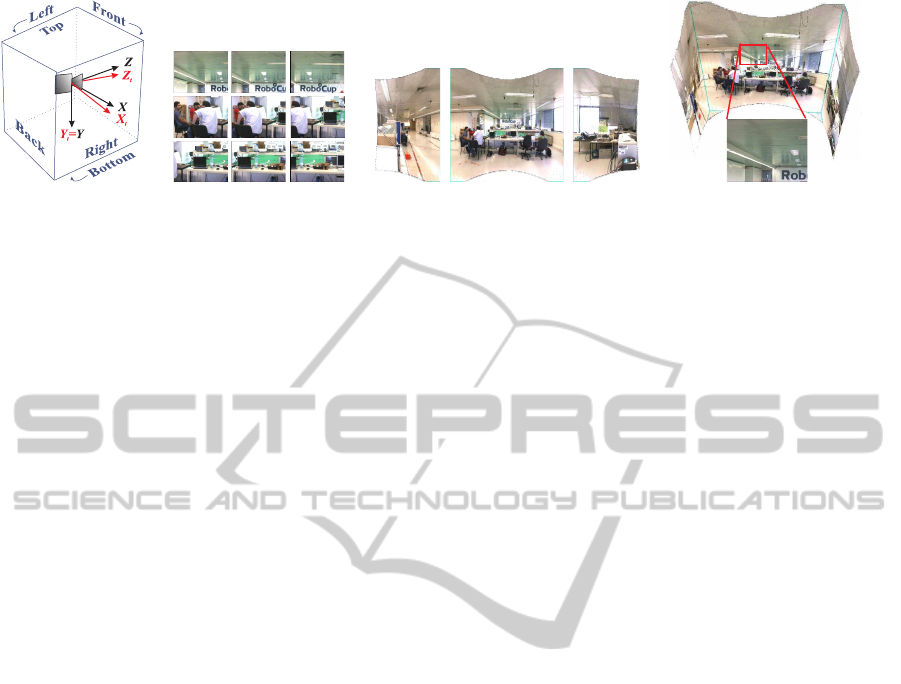
(a) Coordinate systems (b) Sample images (c) Cube faces (d) VRML view
Figure 1: Cube based background representation. (a) Coordinate systems of the cube, {X,Y,Z} and the pan-tilt camera,
{X
t
,Y
t
,Z
t
} with zero tilt and non-zero pan. (b) A number of the images captured to build a mosaic. (c) Left, front and right
cube mosaicked-faces. (d) VRML view of the cube model showing one of the acquired images.
to encompass radiometric calibration to estimate the
radiometric response and vignetting functions of a
camera. Grossberg and Nayar introduced a camera
response model based on a large database of response
functions obtained from well controlled illumination
and color pattern setups (Grossberg and Nayar, 2003).
Kim and Pollefeys proposed estimating the vignetting
and radiometric response functions for high dynamic
range mosaics, from a set of images with different ex-
posures values (Kim and Pollefeys, 2008). Lin et al.
proposed to estimate the radiometric response func-
tion from images without changes in the exposure, us-
ing histograms of the edges regions (Lin and Zhang,
2005). However, vignetting is not considered in the
estimation of the radiometry. Zheng et al. also pro-
posed the correction of vignetting from a single im-
age, but requiring large piecewise flat regions in the
image, which is highly dependent on the scene con-
tents (Zheng et al., 2009).
Alternatively, Wonpil Yu proposed to correct vi-
gnetting based on a white pattern (Yu, 2004). The
white image, decreasing in brightness towards the
borders due to a vignetting distortion function, was
approximated with a 2D hypercosine function. This
calibration methodology is however cumbersome due
to the requirement of having to use very large patterns
when the cameras to calibrate are far away, e.g. out-
doors at a second level floor, as it is usual with surveil-
lance cameras.
In this work we propose therefore using the geo-
metric calibration procedures adapted to pan-tilt cam-
eras, and propose exploring the pan and tilt degrees
of freedom instead of requiring large constant color
areas in the scenarios, or color calibrating patterns.
This paper is organized as follows: Section 2 de-
scribes the geometrical model and the background
representation for pan-tilt cameras, Section 3 dis-
cusses and proposes methodologies to correct the ef-
fect of vignetting on the background variance and
event detection, Section 4 shows experiments test-
ing the proposed methodologies, and finally Section
5 summarizes the work and draws some conclusions.
2 PANORAMIC SCENE
REPRESENTATION
The background scene of a pan-tilt camera can be rep-
resented in various ways, such as a plane, a cylin-
der, a sphere or a cube. In particular we select the
cube based representation as it can handle a complete
spherical field-of-view (FOV), 360
o
× 360
o
, which is
not possible in the planar or cylindric mosaics, and
maps perspective images to/from the background us-
ing just homographies (as compared to using spheri-
cal mappings). See Fig. 1.
Building the cube based representation is a two
steps process: (i) obtaining a back-projection for each
image point and (ii) projecting the back-projection to
the right face of the cube. If one knows the intrin-
sic parameters matrix, K and the orientation R of the
camera, then each image point, m can be easily back-
projected to a 3D world point [x y z]
T
= (KR)
−1
m .
Projecting the world point to the right face of the cube
involves determining the face, namely front, back,
left, right, top or bottom (see Fig. 1a), and then com-
puting the 2D coordinates within that face. The cube
face where to project a world point is determined di-
rectly by inspecting the point coordinates. Defining
v = max(|x|,|y|, |z|), one has that [x y z]
T
is imaged in
the right, left, bottom, top, front or back face of the
cube if v ≡ x,−x, y,−y,z or −z, respectively.
Having identified the cube faces for mapping the
image points, the mapping process consists simply in
projecting the back-projections of the image points
using a projection matrix P
WF
= K
F
[R
WF
0
3×1
],
where K
F
is an intrinsic parameters matrix charac-
terizing the resolution (size) of the cube faces, and
R
WF
are rotation matrices defining optical axis or-
thogonal to the cube faces. The rotation matrices R
WF
VIGNETTING CORRECTION FOR PAN-TILT SURVEILLANCE CAMERAS
639
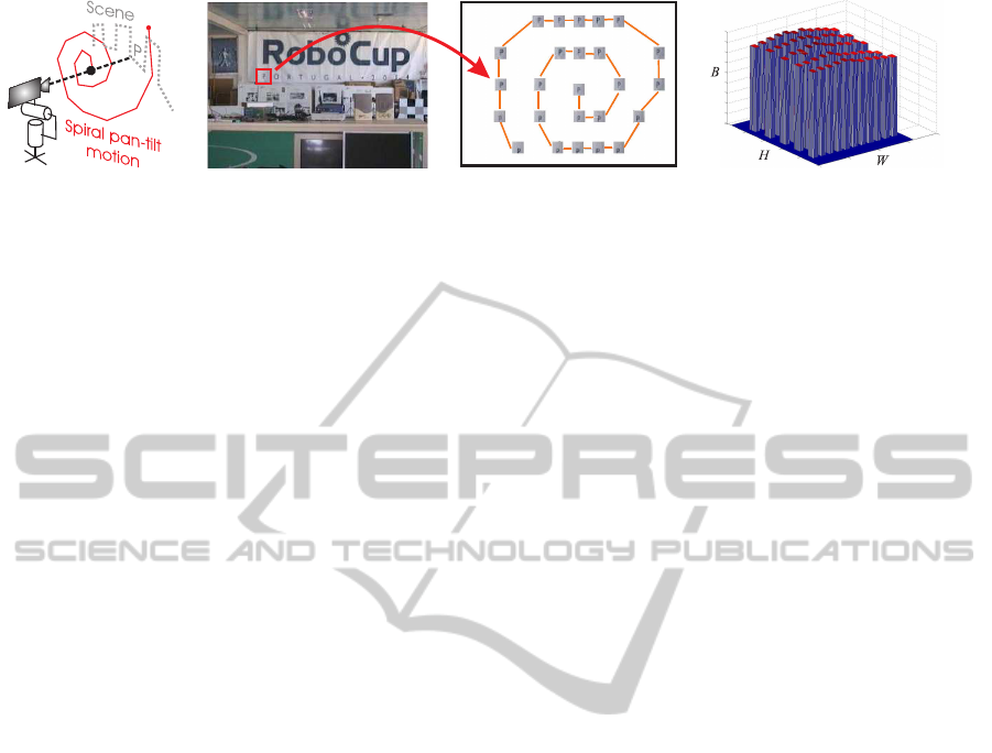
(a) Pan-tilt spiral (b) One image sample and the CRI (c) The CRI as a 3D mesh
Figure 2: Building a Constant Radiance Image (CRI). Camera motion (a) and sample (patch) collection (b). (c) Regular grid
of patches, with brightness B, in a W × H CRI, obtained with approx. constant pan-tilt steps (d).
in essence rotate the 3D points closest to each of the
faces of the cube towards the front face. For example
R
WF
is Rot
Y
(180
o
) or Rot
X
(−90
o
), for the back or top
cube faces, respectively. In summary, an image point
m
i
is mapped to a point on a cube face m
Fi
as:
m
Fi
∼ K
F
R
WF
R
−1
K
−1
m
i
(1)
where ∼ denotes equality up to a scale factor.
Final note, in order to map an image to the cube,
one has to know precisely the camera orientation, R
and the intrinsic parameters, K. In this work we
assume that R is given by the camera control sys-
tem, while K is calibrated using corresponding points
found in images taken at various pan-tilt poses.
3 UNCERTAINTY ANALYSIS AND
EVENT DETECTION
In this section we describe the radiometric model of
image formation process, having as principal com-
ponents the radiometric response function and vi-
gnetting, and propose a patternless-methodology to
estimate and correct the vignetting in pan-tilt cam-
eras.
The effect of the radiometric response function
and vignetting in the image formation process can be
described as (Grossberg and Nayar, 2003; Yu, 2004;
Kim and Pollefeys, 2008; Zheng et al., 2009) :
I(m) = f (kV(m)L(m)) (2)
where I(m) is the image intensity at the image point
m, f(.) is the radiometric response function, k is the
exposure time, L(m) the radiance of a scene point im-
aged at m, and V(m) is the vignetting gain at m. Note
that both f(.) and V(m) have nonlinear natures, f(.)
depends on the pixel brightness / color, while V(m)
depends on the pixel location, such that central pix-
els tend to be unmodified, i.e. V(m) = 1 and pix-
els in the border of the image have lesser brightness
(V(m) < 1).
The patternless methodology for estimating vi-
gnetting is based on a mosaicked image, the Constant
Radiance Image, which is composed from a number
of images taken at various pan-tilt poses. The con-
struction of this composed image is described in the
following.
3.1 Constant Radiance Images
A static object illuminated by a constant light source
emits a constant radiation. Contrarily to the radiance,
the observed irradiance at the image plane of a mov-
ing pan-tilt camera is not constant. It varies with the
pan-tilt pose of the camera e.g. due to vignetting. In
order to describe the varying irradiance of a single
world point captured by moving pan-tilt cameras, it
is convenient to construct what we define as Constant
Radiance Images. These images represent the irradi-
ance of a single world point when it is observed at
different image coordinates.
The construction of a Constant Radiance Image,
C
mo
, with a pan and tilt camera starts simply by choos-
ing one image point, m
o
= [u
o
v
o
1]
T
, computing its
back-projection to a 3D point, and then moving (ro-
tating) the camera, R
i
, and re-projecting the 3D point
to obtain the new image point m
i
:
C
mo
(m
i
) = I
i
(m
i
)
= I
i
(KR
i
R
−1
o
K
−1
m
o
). (3)
Figure 2 shows the construction of one C
mo
, and illus-
trates the typical aspect of a vignetting effect.
Assuming that (i) one estimates the radiometric
response function f(.), using e.g. the method in (Lin
et al., 2004), then one can remove the effect of f(.) by
redefining I(m) → f
−1
(I(m)), (ii) the exposure time k
is the same for backgroundconstruction and event de-
tection, then it is no longer a distinguishing factor and
we can use without loss of generality that k = 1, and
(iii) the maximum of the vignetting gain is unitary,
i.e. keeps unchanged a number of central pixels of the
original image, then one finds that one Constant Ra-
diation Image characterizes the vignetting. More pre-
cisely, C
m0
(m) = f
−1
( f (kV(m)L(m))) = V(m)L(m),
and the vignetting gain can be estimated as V(m) =
C
mo
(m)/max(C
mo
(m)).
VISAPP 2011 - International Conference on Computer Vision Theory and Applications
640

3.2 Vignetting Correction
Given the estimated vignetting function, V(m), one
desires to apply a correction function, V
c
(m) that ap-
proximates the captured image equal to the radiance
image:
I
c
(m) = V
c
(m)I(m) = V
c
(m)V(m)L(m) (4)
i.e. one wants V
c
(m) = V
−1
(m), which means
V
c
(m) = max(C
mo
(m))/C
mo
(m). This approach has
however two problems, it requires a dense pan-tilt
sweeping to fill all the pixels of a Constant Radiance
Image, and it is affected by image noise. We pro-
pose therefore an optimization methodology having a
smooth interpolating (parametric) vignetting correc-
tion function.
The parametric vignetting correction function is
in general a function that keeps the center pixels
unchanged, and gradually enhances (augments) the
brightness of the pixels closer to the border. In the
literature one finds for example sums of even pow-
ers of radial distances (see e.g. (Kim and Pollefeys,
2008)). In this work we follow the suggestion of (Yu,
2004):
V
c
(m;a) = cosh(a
1
(u− u
p
))cosh(a
2
(v− v
p
)) + a
3
(5)
where m = [u v 1]
T
is an image point, m
p
= [u
p
v
p
1]
T
is the principal point, and the vector a = [a
1
a
2
a
3
]
T
contains the parameters characterizing the correction.
Having defined the fitting function, we can know
describe the optimization procedure to find the vi-
gnetting correction as:
a
∗
= arg
a
min
∑
m
max(C
mo
(m))
C
mo
(m)
−V
c
(m;a)
2
(6)
which can be solved iteratively with the Levenberg-
Marquardt algorithm.
3.3 Radiometric Background Modeling
Given V
c
(m), we can now correct all acquired images,
I(m) := V
c
(m;a)I(m), which is beneficial for the con-
struction of panoramic background representations.
A panoramic background representation com-
prises the superposition of various images, acquired
at different pan-tilt poses. Thus, the same 3D ob-
ject seen at various pan-tilt poses, despite having a
constant radiance, has a varying (captured) irradiance
imposed by the vignetting. A background model is
usually represented by the mean value and variance
of the irradiance at eack background location M, re-
spectivelly µ
B(M)
and σ
2
B(M)
. Without vignetting cor-
rection the “gray level” value of a background loca-
tion will change as the camera rotation changes. The
values of the background thus depend not only on im-
age noise but also on the changes due to vignetting in
the imaged pixelV(m), which can now be considered
a random variable with mean, µ
V(m)
, and a variance,
σ
2
V(m)
:
B(M) = L(M)V(m) + η (7)
where η is a noise process, and L(M) denotes the radi-
ance that is expected to be observed at the background
pixel M. Taking expected values we get:
µ
B(M)
= L(M) µ
V(m)
σ
2
B(M)
= L
2
(m) σ
2
V(m)
+ σ
2
η
(8)
where σ
2
η
is the noise variance. The vignetting correc-
tion allows to decrease the variance at the superposi-
tion as shown next.
Considering that the processes of vignetting and
vignetting-correction can characterized by a mean
gain, µ
V
c
(m)V(m)
, and a variance of gains, σ
2
V
c
(m)V(m)
,
then we have that the background mean and vari-
ance are µ
B(M)
= L(M) µ
V
c
(m)V(m)
and σ
2
B(M)
=
L
2
(m) σ
2
V
c
(m)V(m)
+ σ
2
η
. In the case of not having vi-
gnetting correction, V
c
(m) = 1, we have that the vi-
gnetting directly effects on the image, µ
V
c
(m)V(m)
=
µ
V(m)
and σ
2
V
c
(m)V(m)
= σ
2
V(m)
. On the other hand, if
one has a perfect correction, V
c
(m) = V(m)
−1
, then
we have a perfect observation of the scene radiance
µ
B(M)
= L(M) and a zero variance on the background
representation, σ
2
B(M)
= L
2
(M) × 0 = 0.
3.4 Event Detection
Event detection is done by comparing a currently
captured image, vignetting-corrected, I(m) with the
corresponding image retrieved from the background
database, B(m), using the background variance, σ
2
B(m)
as a normalizing factor:
D(m) =
(I(m) − B(m))
2
/σ
2
B(m)
1/2
(9)
A pixel m is considered active, i.e. foreground, if
D(m) ≥ 3.
4 EXPERIMENTS
This section describes two experiments: (i) testing
the relationship between the variance of the vignetting
gains within a simulated white scenario such that the
images exhibit directly the vignetting effect, and (ii)
event detection on a real setup.
VIGNETTING CORRECTION FOR PAN-TILT SURVEILLANCE CAMERAS
641

4.1 Simulated White Scenario
In this experiment the scene luminance, L(M) is con-
stant. The vignetting correction gain, V
c
(m;a
r
) with
a
r
= [a
r1
a
r2
a
r3
]
T
, is the one obtained from a real cam-
era (see Sec. 3.2). Vignetting distortion is defined as
V(m;a
r
) ˙=1/V
c
(m;a
r
).
In order to compare various combinations of vi-
gnetting distortion and correction, we vary both both
of them in a parametric manner, by scaling the pa-
rameters. More precisely, we use V(m;αa
r
) and
V
c
(m;βa
r
), with α ∈ {0,.3, .6,1,1.3,1.6} and β ∈
{0,.5, 1,1.1, 1.2,1.5}. Note that α = 1 corresponds
to introducing the reference vignetting, while α = 0
corresponds to not introducing vignetting. Similarly,
β = 0 and β = 1 correspond to no vignetting correc-
tion and to perfect correction, respectively.
Figure 3 shows in the vertical axis an experimen-
tal estimate of the standard deviation of a background
pixel, ρ
B(m)
, which is obtained as the square root of
the variance, σ
2
B(m)
estimated empirically from the
cube based representation constructed from a set of
images acquired at various pan-tilt poses. In the hor-
izontal axes, Fig. 3 has the theoretical estimate of the
background standard deviationconsidering there is no
vignetting correction, i.e. ρ
VL
=
q
L
2
σ
2
V(m)
, and the
parameter β regulating the amount of vignetting cor-
rection.
From Eq.8 with σ
2
η
= 0 one has that ρ
B(m)
≡ ρ
VL
only when β = 0. Otherwise, one may have ρ
B
(m) = 0
when the vignetting correction removes perfectly the
vignetting distortion, β = 1, which is confirmed by
the plot.
0
5
10
15
20
0
0.5
1
1.5
0
10
20
30
← No correction
← Perfect correction
ρ
VL
Correction β
Experimental ρ
B
Figure 3: Background standard deviation vs vignetting ef-
fects and corrections. The correction β is adimensional,
while ρ
VL
and ρ
B
have their dimensions defined in a 8 bits
gray-scale space.
4.2 Event Detection in a Real Scenario
We use a Sony EVI D30 to scan a room and create
two background representations: one lacking and the
other one having vignetting-correction (Fig. 4(b) and
(c), resp.). These representations result from 347 im-
ages, acquired with approximately 2
o
in pan and 3.5
o
in tilt steps.
The images with events to be detected during the
run time, were created afterwards using a video pro-
jector superimposing text (digits) towards the ceiling
of the room. The digits are progressively less visi-
ble toward the borders in order to test the limits of
the proposed event detection methodology. Two run-
time images are shown in Fig. 4(d). For comparison
purposes, a mosaic built from 48 run-time images is
shown in Figs. 4(e,f), without and with vignetting cor-
rection, respectively. The pan and tilt steps are about
5
o
and 10.5
o
, being therefore much larger than in the
database images. The fields of view do not match ex-
actly the ones of the images of the database.
Our event detection methodology is based on
comparing the run time images (not the run time mo-
saics, which in general are not available) with match-
ing database images extracted from the background
mosaics (Figs. 4(c)). In the case of using vignetting
correction it is applied to the run time images before
comparing them with the background (Fig. 4(c)).
Figures 4(g,h) show the estimated vignetting cor-
rection function and the change motivated by vi-
gnetting correction on a scan-line of a mosaic (we are
displaying just 1/3 of the scan-line). As expected, the
vignetting correction gradually enhances (augments)
the brightness values when walking towards the im-
age periphery, and the mosaic scan-lines are much
smoother after vignetting correction.
Figures 4(i,j) show correct detections of digits, us-
ing or not vignetting correction, however one sees
more detections (true positives) and less false de-
tections (false positives) when there is used the vi-
gnetting correction. The brightness differences moti-
vated by the vignetting when compared with the back-
ground, built just keeping at each location the most
recent image pixel or averaging all superimposed-
image-pixels hitting that location, are significantly
more relevant than when using the vignetting correc-
tion.
5 CONCLUSIONS
In this paper we proposed a vignetting correction
method for pan-tilt cameras. Experiments haveshown
that the correction allows building (mosaicked) scene
representations with less variance and therefore more
effective for event detection. Future work will fo-
cus on maintaining minimized variance representa-
tions accompanying the daylight change.
VISAPP 2011 - International Conference on Computer Vision Theory and Applications
642
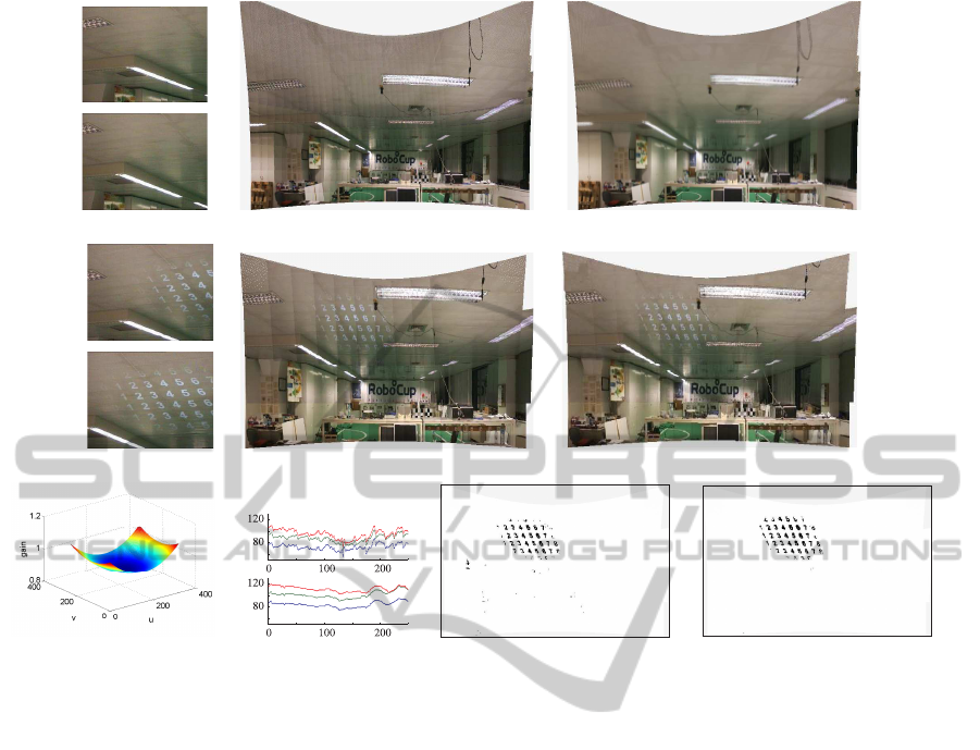
(a) Database (b) Database mosaic (c) With vignetting correction
(d) Run time (e) Run time mosaic (f) With vignetting correction
(g) Correction gain (h) Scanline profiles (i) Results of BS using (b) (j) Results of BS using (c)
Figure 4: Event detection experiment. (a,b,c) Two database images of a set of 347, the database mosaic before and after
vignetting correction. (d,e,f) Two run time images, a mosaic built from 47 run time images, and the same mosaic with
vignetting correction. (g) Vignetting correction gain. (h) Top and bottom plots are scanlines of (b) and (c), respectively. (i,j)
Display in mosaics of events found in the run time images (some examples in (d)) using the database mosaics (b) and (c).
ACKNOWLEDGEMENTS
This work has been partially supported by the
Portuguese Government - FCT (ISR/IST pluri-
annual funding) through the PIDDAC program
funds, and by the project DCCAL, PTDC / EEA-
CRO / 105413 / 2008.
REFERENCES
Agapito, L., Hartley, R., and Hayman, E. (1999). Linear
calibration of a rotating and zooming camera. In Pro-
ceedings of the IEEE Conference on Computer Vision
and Pattern Recognition, pages 15–21. IEEE Com-
puter Society, Fort Collins, Colorado, USA.
Anderson, C. H., Bergen, J. R., Burt, P. J., and Ogden, J. M.
(1984). Pyramid methods in image processing. RCA
Engineer, 29(6):33–41.
Brown, M. and Lowe, D. (2003). Recognising panoramas.
Computer Vision, 2003. Proceedings. Ninth IEEE In-
ternational Conference on, pages 1218 –1225 vol.2.
Grossberg, M. and Nayar, S. (2003). What is the space
of camera response functions? In IEEE Conference
on Computer Vision and Pattern Recognition (CVPR),
volume II, pages 602–609.
Hartley, R. I. (1994). Self-calibration from multiple views
with a rotating camera. In In Proceedings of the Euro-
pean Conference on Computer Vision, pages 471–478.
Springer-Verlag.
Kim, S. J. and Pollefeys, M. (2008). Robust radiometric
calibration and vignetting correction. IEEE T-PAMI,
30(4):562 –576.
Levin, A., Zomet, A., Peleg, S., and Weiss, Y. (2006).
Seamless image stitching in the gradient domain. In
In Proceedings of the European Conference on Com-
puter Vision.
Lin, S., Gu, J., Yamazaki, S., and Shum, H.-Y. (2004). Ra-
diometric calibration from a single image. Computer
Vision and Pattern Recognition, IEEE Computer So-
ciety Conference on, 2:938–945.
Lin, S. and Zhang, L. (2005). Determining the radio-
metric response function from a single grayscale im-
age. Computer Vision and Pattern Recognition, IEEE
Computer Society Conference on, 2:66–73.
VIGNETTING CORRECTION FOR PAN-TILT SURVEILLANCE CAMERAS
643

Sinha, S. N. and Pollefeys, M. (2006). Pan-tilt-zoom cam-
era calibration and high-resolution mosaic generation.
Comput. Vis. Image Underst., 103(3):170–183.
Yu, W. (2004). Practical anti-vignetting methods for digital
cameras. Consumer Electronics, IEEE Transactions
on, 50(4):975 – 983.
Zheng, Y., Lin, S., Kambhamettu, C., Yu, J., and Kang,
S. B. (2009). Single-image vignetting correction. Pat-
tern Analysis and Machine Intelligence, IEEE Trans-
actions on, 31(12):2243 –2256.
VISAPP 2011 - International Conference on Computer Vision Theory and Applications
644
