
RAINDROP COMPLEMENT BASED ON EPIPOLAR GEOMETRY
AND SPATIOTEMPORAL PATCHES
Kyohei Nomoto, Fumihiko Sakaue and Jun Sato
Nagoya Institute of Technology, Gokiso, Showa, Nagoya 466-8555, Japan
Keywords:
Auto-epipolar geometry, Spatiotemporal image, Image in-painting.
Abstract:
In this paper, we propose detection and complement of raindrops on mirrors and windows onto cars. Raindrops
on windows and mirrors disturb view of drivers. In general, they were removed using wiper and special
devices. However, the devices cannot be used for general case. In our proposed method, images of mirrors
and windows are taken by camera and raindrops are complemented on the images, virtually. The method is
based on auto-epipolar geometry and concept of spatiotemporal image. By using the method, we can observe
clear windows and mirrors only if we can take them by camera.
1 INTRODUCTION
Recently, multiple cameras are equipped on vehicles
for various kinds of purposes. These vehicle cameras
obtain lots of information which can help drivers. The
extracted information is presented to drivers in var-
ious ways. For example, virtual dead angle images
of driver’s view can be synthesized by using multi-
ple vehicle cameras. From these images, drivers can
observe pedestrians and obstacles in dead angles, and
can avoid car accidents. Many other applications can
be considered for assisting vehicle drivers by using
vehicle cameras. In this paper, we consider a system
which supports drivers in rainy days by using vehicle
cameras.
In rainy days, raindrops on side mirrors and win-
dows disturb drivers view as shown in Fig.1 (a). For
the safety driving, these raindrops should be removed
as shown in Fig.1 (b). Although the raindrops on front
windows can be removed by using wipers, there is no
wipers for raindropson side mirrors and side windows
in general. Thus, we in this paper propose a method
for removing these raindrops not in physical way but
in virtual way. The proposed method can be applied
to not only side mirrors and windows but also other
windows and mirrors to obtain clear views without
using wipers.
In our method, windows and mirrors are taken by
cameras equipped on vehicles, and raindrops in im-
ages are removed by using the image in-painting tech-
nique. By using the proposed method, images without
raindrops can be presented to vehicle drivers, and the
drivers can observe clear windows and mirrors.
In order to achieve raindrop removal, we have
to extract raindrop areas in images and complement
these areas. This is called image complement or im-
age in-painting, and various methods have been pro-
posed. Many others proposed image complement
methods for static scenes viewed from static cam-
eras (Efros and Freeman, 2001; Bertalmio et al.,
2000; Bertalmio et al., 2001; Kang et al., 2002;
Bertalmio et al., 2003; Matsushita et al., 2005; Shen
et al., 2006; Wexler et al., 2007; Hase et al., 1999).
However, these methods cannot be applied for vehicle
cameras, since vehicle cameras are moving rapidly,
and the scene changes continually. Furthermore,
these methods cannot recover large image lack such
as occlusions. Kuribayashi and others proposed im-
age in-painting methods for moving cameras (Kurib-
ayashi et al., 2009). However, these methods are lim-
ited to cameras whose motions are parallel to image
plains. In this case, image motions are constant, and
are parallel to each other. Thus, image in-painting is
rather simple. In our case, camera motions, i.e. mirror
motions, are not parallel to the image plane, and the
image motions are not constant and vary depending
on the 3D position of scene points.
To complement images taken under general trans-
lational cameras, we consider epipolar geometry in
sequential images. In particular we consider the auto
epipolar geometry, which provides us very strong
constraints for complimenting images properly by us-
ing past sequential images.
175
Nomoto K., Sakaue F. and Sato J..
RAINDROP COMPLEMENT BASED ON EPIPOLAR GEOMETRY AND SPATIOTEMPORAL PATCHES.
DOI: 10.5220/0003375001750180
In Proceedings of the International Conference on Computer Vision Theory and Applications (VISAPP-2011), pages 175-180
ISBN: 978-989-8425-47-8
Copyright
c
2011 SCITEPRESS (Science and Technology Publications, Lda.)
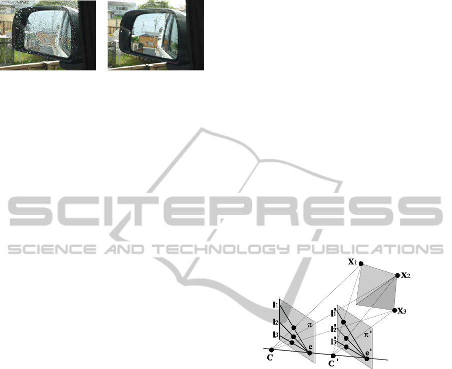
(a) (b)
Figure 1: Images which has raindrops and no raindrops.
2 EPIPOLAR GEOMETRY FOR
TRANSLATING CAMERA
In this paper, we propose a method which enables us
to detect and complement raindrops on mirrors and
windows in images. In this method, we assume that
the images are taken by a translational camera, which
is a reasonable assumption for images taken by vehi-
cle cameras.
If a static scene is observed by a moving camera,
the relationship among sequential images taken by the
moving camera can be described by the epipolar ge-
ometry. Furthermore, if there is no rotation in the
camera motion, i.e. pure translation, the relationship
among images can be described by the auto-epipolar
geometry(Hartley and Zisserman, 2000). When the
auto-epipolar geometry holds, epipoles and epipolar
lines in two different images are equivalent to each
other, and then, the epipolar geometry can be esti-
mated very accurately. In this paper, we use the auto-
epipolar geometry for efficient and stable image com-
plement. In this section, we describe the detail of the
auto-epipolar geometry.
2.1 Auto-epipolar Geometry on
Translational Cameras
In general, the relationship between corresponding
points, x and x
′
, in two different views can be de-
scribed by the following epipolear equation:
x
′⊤
Fx = 0 (1)
where, F is a 7 DOF rank 2 matrix called fundamen-
tal matrix. Note, in this paper, points and lines are
represented by homogeneous coordinates.
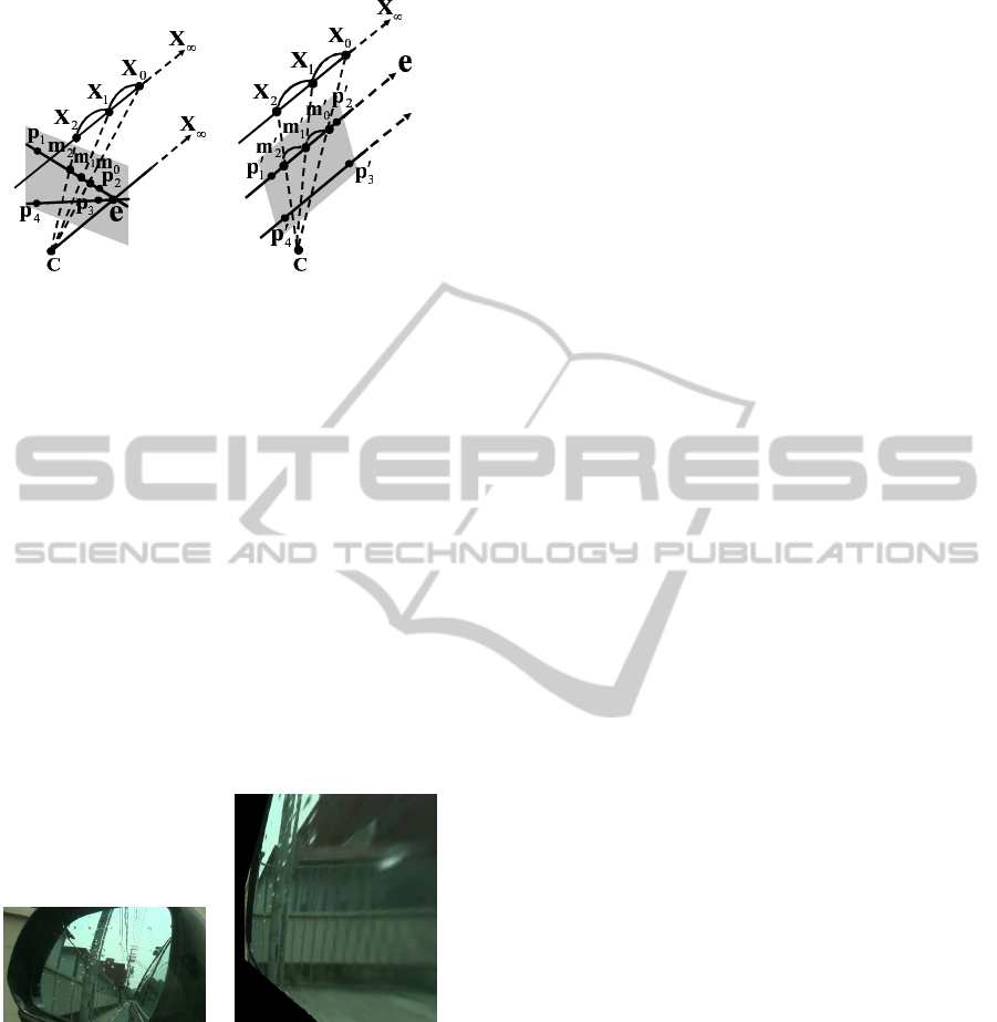
Suppose we have a translational camera as shown
in Fig. 2. The 3D points X
i
(i = 1, ··· , N) are pro-
jected to x
i
and x
′
i
in two images, and epipolar lines l
i
and l
′
i
go through these corresponding points. In this
case, the auto epipolar geometry holds, and the funda-
mental matrix F has only 2 DOF. Thus, the fundamen-
tal matrix can be estimated from only 2 corresponding
points stably. In this case, epipoles and epipolar lines
are identical in two images. Thus, the epipolar line l
i
can simply be estimated by connecting corresponding
points x
i
and x
′
i
as follows:
l
i
= x
i
×x
′
i
(2)
where, × denotes a vector product. Furthermore, the
epipole e can be estimated as an intersection of epipo-
lar lines as follows:
e = l
1
× l
2
. (3)
By using the epipole, the fundamental matrix F is de-
scribed as follows:
F = [e]
×
(4)
where [·] denotes a 3 × 3 skew symmetric matrix,
which represents the vector product. Thus, the fun-
damental matrix can be estimated from minimum of
two corresponding points. Since the DOF of the fun-
damental matrix is much smaller than that of general
case, it can be estimated quite reliably from small
number of corresponding points.
Figure 2: Auto-epipolar geometry on translating cameras.
2.2 Parallelization of Epipolar Lines
In the previous section, we described auto-epipolar
geometry. Under general translational motions, the
epipolar lines are not parallel to each other. Since effi-
cient image processing can be accomplished when the
epipolar lines are parallel to each other, we in this sec-
tion consider parallelization of epipolar lines by using
projective transformation.
The epipolar lines are intersected at an epipole,
and thus, the epipolar lines become parallel to each
other, if the epipole is moved to a point at infin-
ity. Therefore, we estimate a projective transforma-
tion, which moves the epipole to an infinite point.
Such projective transformation H satisfies the follow-
ing equation:
λ
e
1
e
2
0
= He (5)
VISAPP 2011 - International Conference on Computer Vision Theory and Applications
176
(a) (b)
Figure 3: Parallelization of epipolar lines using 2D projec-
tive transformation. (a) shows a general translational cam-
era, and (b) shows the camera after parallelization. The
translational camera can be considered as a static camera
which observe translational 3D points X
i
. The paralleliza-
tion of epipolar lines can be achieved by rotating the image
plane so that it is parallel to the direction of translation.
where e
1
and e
2
denote the first and the second com-
ponents of the epipole e. By using the transformation,
all epipolar lines become parallel to each other. The
transformation H implies image plane rotation, and
the rotated image planes are parallel to the direction
of camera translation as shown in Fig.3.
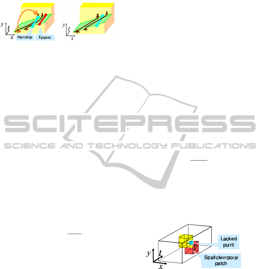
Figure 4 shows example of image paralleliza-
tion. In this figure, a projective image distortion is
eliminated by image parallelization. By using the
transformed images, the image complement can be
achieved efficiently as described in the next section.
(a) original image (b) transformed image
Figure 4: Exampe of image parallelization of a side mirror
image. (a) shows an original image and (b) shows the image
after parallelization of epipolar lines.
3 IMAGE COMPLEMENTS
USING SPATIOTEMPORAL
PATCHES
3.1 Complementation of Raindrop
In the previous section, we considered geometric
properties of sequential images captured from trans-
lational cameras and their parallelization. In this
section, we propose an image complement method
for parallelized sequential images. Although rain-
drops on windows and mirrors must be detected be-
fore image complement, we consider the image com-
plement method before considering the raindrop de-
tection method, since the raindrop detection method
is based on image complement in our method.
In the sequential images of a camera mounted on
a moving vehicle, image pixels occluded by raindrops
can be observed in other frames. Thus, the occluded
pixels can be inpainted by using image information
in other frames. Wexler proposed image comple-
tion method for spatiotemporal images(Wexler et al.,
2007). In their method, they considered not only cur-
rent single frame, but also multiple sequential frames,
and spatiotemporal patches are used for image com-
pletion. However, their method can only be applied
to the scene taken by a fixed camera, and thus, it can-
not be applied to image sequences taken by a trans-
lational camera. In order to inpaint images taken by
translational cameras, we extend their method by us-
ing auto-epipolar geometry.
3.2 Image Complements using
Spatiotemporal Images
Now, let us consider sequential images taken by a
translational camera. As shown in section 2, the auto-
epipolar geometry holds in this case. In this paper,
we consider the sequential images as a spatiotem-
poral image as shown in Fig.5 (a). When the auto-
epipolar geometry holds, epipolar lines and epipoles
in sequential images are identical to each other. Thus,
if we consider a slice along an epipolar line, we have
the slice which represents image point motions in the
translational camera as shown in Fig.5 (a). In this
slice, the epipole does not move because of the auto-
epipolar. The raindrops also do not move. On the
other hand, background objects such as trees move on
the epipolar lines as shown in Fig.5 (a). Furthermore,
when images are parallelized by the method described
in section 2.2, background objects move linearly as
shown in Fig.5 (b). In this case, we can estimate the
movement of the background objects easily. Thus,
simple image complements can be achieved.
3.2.1 Pixels Complement using Spatiotemporal
Patches
In this section, we consider image inpainting by us-
ing spatiotemporal patches. The spatiotemporal patch
is a 3-dimensional patch in the spatiotemporal image
RAINDROP COMPLEMENT BASED ON EPIPOLAR GEOMETRY AND SPATIOTEMPORAL PATCHES
177
(a) (b)
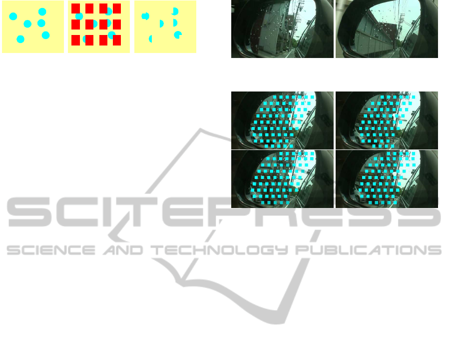
Figure 5: Epipole and raindrop on spatiotemporal slice.
as shown in Fig.6. Note, we can only use past image
frames for image inpainting, which are taken before
the current image frame, since we cannot predict fu-
ture images.
Now, let us consider a current image, in which
a lacking image pixel exists because of a raindrop.
If we consider the image sequence, the laking pixel
can be considered as a point in the 3D spatiotempo-
ral space as shown in Fig.6. In this 3D space, the
spatiotemporal patches which include the laking pixel
are considered as template patches. For example, 125
template patches can be considered, if the size of the
patch is 5 × 5 × 5. However, the template patches
which include future image points cannot be used for
image inpainting, and thus only 25 template patches
can be selected if the size of the patch is 5× 5× 5.
For the image complement, we consider the co-
herence between a spatiotemporal image S and a ref-
erence spatiotemporal image D in the database. The
database is constructed from current and past image
frames. Let us consider a point p in S and a point q
in D. Then, we define the similarity between a spa-
tiotemporal patch W
p
in S and a spatiotemporal patch
V
q
in D as follows:
s(W
p
, V
q
) = e
−
d(W
p
,V
q
)
2σ
2
(6)
where σ is the standard deviation of Gaussian image
noise on image intensity, and d(W
p
, V
q
) denotes the
L2 distance between W
p
and V
q
as follows:
d(W
p
, V
q
) =
∑
(x,y,t)
||W
p
(x, y, t) −V
q
(x, y, t)||
2
(7)
Then, the the coherence between a spatiotemporal im-
age S and a reference spatiotemporal image D in the
database can be defined as follows:
Coherence(S|D) =
∏
p∈S
max
q∈D
s(W
p
, V
q
) (8)
The spatiotemporal image S which provides us a max-
imum coherence is chosen as the complemented spa-
tiotemporal image.
Although the database includes all spatiotempo-
ral images up to the current time, the spatiotemporal
patch for p is chosen from patches which are close to
the epipolar line of pixel p. By using this constraint,
the search space becomes small, and hence the com-
putational cost of image complement becomes small.
Furthermore, errors in the selection of spatiotemporal
patch also become small.
Let us describe estimation of pixel value c for lak-
ing point p. The pixel value c of p is determined as
coherences for all spatiotemporal templatesW
i
p
(some
spatiotemporal template can be selected for laking
pixel p) become higher. The problem can be repre-
sented as minimization of the following equation.
∑
i
ω
i
p
(c− c
i
)
2
(9)
where c
i
is a pixel value for p in V
i
which is the near-
est spatiotemporal patch in the database. The variable
ω
i
p
is determined as follows:
ω
i
p
= γ
−dist
s(W
i
p
, V
i
) (10)
where γ is a constant and dist is a distance from pixel
p to the nearest background pixel in the image. Thus,
pixel value c is determined as follows:
c =
∑
i
ω
i
p
c
i
∑
i
ω
i
p
(11)
The complemented image S is updated by using the
value c. The database D is also updated so that the
database includes complemented images. These pro-
cesses are iterated until the complemented image con-
verges. The pixel values of laking pixels are estimated
by the process, and thus, the raindrops can be comple-
mented if they are detected, accurately.
Figure 6: Spatiotemporal patch for complement of laking
point.
4 RAINDROP DETECTION
USING IMAGE COMPLEMENT
We next propose a method for detecting raindrops by
using the image complement method described in the
previous section. We first consider a mask of image
as shown in Fig.9 (b). The masked areas are inpainted
by the method described in the previous section, and
inpainted image (c) can be obtained. Although there
VISAPP 2011 - International Conference on Computer Vision Theory and Applications
178
(a) Input image (b) Masked image (c) Assumed
complemented
image
Figure 7: Raindrop detection using masked image.
are some raindrops in the input image, it is not a prob-
lem for image complement, since raindrop areas are
not used for image complement in general. This is
because if the raindrop areas are used for image com-
plement, coherence of spatiotemporal image becomes
low, and thus image complements are achieved by us-
ing just background areas.
By changing the mask patterns and complement-
ing images, whole image can be inpainted. This
method roughly delete raindrops in images, and thus
the difference between the obtained image and the in-
put image becomes large at raindrop areas. Therefore,
raindrops can be extracted by thresholding the differ-
ence image.
By combining the detection method with comple-
ment method, we can extract raindrops and eliminate
them in images.
5 EXPERIMENT
5.1 Experimental Environment
In this section, we show some experimental results
by using the proposed method. In this experiment, a
camera is attached near the driver’s eyes, and the cam-
era observes the side mirror of the vehicle. The size
of the image is 360 × 240, and the frame rate of the
camera is 30 fps. the speed of the vehicle was about
40 km/h, and 400 image frames were taken. Some
example images obtained from the camera are shown
in Fig.8. As shown in this figure, raindrops exist in
images.
For raindrop detection, 4 patterns of mask image
were used, which are shown in Fig.9. Size of spa-
tiotemporal patch is 5× 5× 5 and 60 past frames were
used for database of image complement.
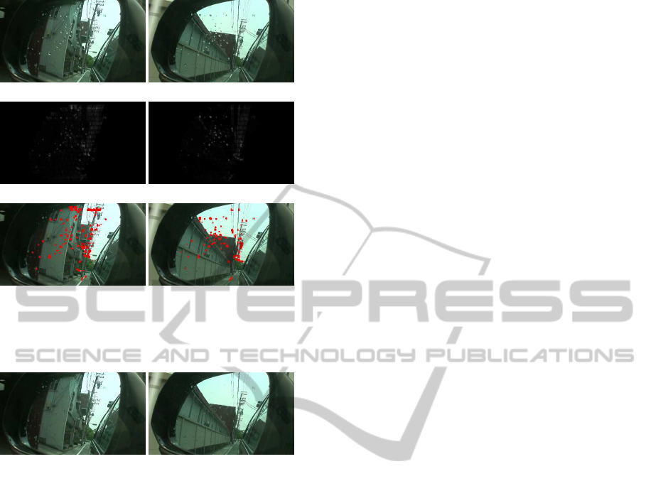
5.2 Results of Raindrop Detection and
Complement
In this section, we show the results of raindrop detec-
tion. Fig.10 (a) shows input images for raindrop de-
Figure 8: Input images.
Figure 9: Masking images for raindrop detection.
tection. The raindrops in these images are extracted
by using the method proposed in section 4. Fig.10 (b)
shows difference between input images and roughly
inpainted images, and Fig.10 (c) shows raindrops de-
tected by thresholding the difference image in (b).
From these results, most part of raindrops on the mir-
ror can be detected by the proposed method. How-
ever,some strong edges are also detected as raindrops.
This is because our image complement method be-
comes unstable around strong edges, and it causes
wrong extraction of raindrops.
The extracted raindrops in images were next com-
plemented by using the method proposed in section 3.
Fig. 11 shows images generated from the proposed in-
painting method. Comparing these images with those
in Fig.10 (a), we find that most of the raindrops are
inpainted accurately by using the proposed method.
Furthermore, strong edge areas extracted as raindrops
by mistake were also inpainted properly. Thus, we
find that the over extraction of raindrops area does not
cause serious problem in our method.
6 CONCLUSIONS
In this paper, we proposed a method for detecting and
complementing raindrops on mirrors and windows of
vehicles virtually.
We first described a method for complementing
raindrops by using the auto-epipolar geometry among
sequential images. Since vehicle cameras can be con-
sidered as translational cameras in short periods, the
auto-epipolar geometry holds and it can be used for
RAINDROP COMPLEMENT BASED ON EPIPOLAR GEOMETRY AND SPATIOTEMPORAL PATCHES
179
(a) input images
(b) differences
(c) detected raindrops
Figure 10: Detection result of raindrops on a side mirror:
Input images (a), image differences of virtual image (b) and
detection results (c).
Figure 11: Results of raindrop complement. Comparing
these images with those in Fig.10 (a), we find the raindrops
are inpainted properly by using the proposed method.
complementing images efficiently. The pixel values
of laking pixels are recovered from the coherences of
spatiotemporal images.
We next showed that raindrops can be extracted
accurately by using the image complement method,
and proposed a method for extracting raindrops by
complementing masked images. The extracted rain-
drop areas were inpainted and raindrops are elimi-
nated in images.
The experimental results show that the proposed
method works very well for real image sequences
with raindrops.
REFERENCES
Bertalmio, M., Bertozzi, A. L., and Sapiro, G. (2001).
Navier-stokes, fluid dynamics, and image and video
inpainting. In Proceedings of the 2001 IEEE Com-
puter Society Conference on Computer Vision and
Pattern Recognition (CVPR2001), volume 1, pages
355–362.
Bertalmio, M., Sapiro, G., Caselles, V., and Ballester,
C. (2000). Image inpainting. In ACM Transac-
tions on Computer Graphics (Proceedings of SIG-
GRAPH2000), pages 417–424.
Bertalmio, M., Vese, L., Sapiro, G., and Osher, S. (2003).
Simultaneous structure and texture image inpainting.
IEEE Transactions on Image Processing, 12(8):882–
889.
Efros, A. and Freeman, W. (2001). Image quilting for tex-
ture synthesis and transfer. In Proc. SIGGRAPH ’01,
pages 341–346.
Hartley, R. and Zisserman, A. (2000). Multiple View Geom-
etry in Computer Vision. Cambridge University Press.
Hase, H., Miyake, K., and Yoneda, M. (1999). Real-time
snowfall noise elimination. In Proceedings of the 1999
IEEE International Conference on Image Processing
(ICIP1999), volume 2, pages 406–409.
Kang, S., Chan, T., and Soatto, S. (2002). Inpainting from
multiple views. In Proceedings of the 1st Interna-
tional Symposium on 3D Data Processing Visualiza-
tion and Transmission, pages 622–625.
Kuribayashi, K., Ono, S., Kawasaki, H., and Ikeuchi, K.
(2009). Spatio-temporal image filter for removal of
obastacles from on-vehicle video data. In Meeting on
Image Recognition and Understanding, pages 1065–
1072.
Matsushita, Y., Ofek, E., Tang, X., and Shum, H. (2005).
Full-frame video stabilization. In Proceedings of the
2005 IEEE Computer Society Conference on Com-
puter Vision and Pattern Recognition (CVPR2005),
volume 1, pages 50–57.
Shen, Y., Lu, F., Cao, X., and Foroosh, H. (2006). Video
completion for perspective camera under constrained
motion. In Proceedings of the 18th International
Conference on Pattern Recognition (ICPR2006), vol-
ume 3, pages 63–66.
Wexler, Y., Shechtman, E., and Irani, M. (2007). Space-time
completion of video. IEEE Transactions on Pattern
Analysis and Machine Intelligence, 29(3):463–476.
VISAPP 2011 - International Conference on Computer Vision Theory and Applications
180
