
SKETCHED INTERACTION METAPHORS FOR CHARACTER
ANIMATION
Konstantin Schauwecker, Simon van den Hurk, Wallace Yuen and Burkhard C. W
¨
unsche
Department of Computer Science, University of Auckland, Private Bag 92019, Auckland, New Zealand
Keywords:
Sketch-based interfaces, Character animation, Skeletal animation.
Abstract:
The use of 3D virtual worlds is increasing rapidly and new tools are necessary to enable untrained users to cre-
ate 3D content and interact with it. In this paper we present and evaluate sketch-based interaction metaphors
for specifying complex animations of 3D skeletally animated models. Sketched interactions include bone ro-
tation, motion path translation, sequencing and synchronisation of animations, and an undo-functionality. The
sketches are drawn directly onto a model in a 3D view and are translated into time-dependent joint transforma-
tions. A user study demonstrates that the animation metaphors are intuitive, with the exception of animation
ordering. More work is necessary to synchronise animations better. Overall our research demonstrates that
sketched-based animations can be useful for applications requiring rapid prototyping containing a limited
number of joint animations. Examples are the programming of household robots and the creation of simple
animated scenes in education and social network applications.
1 INTRODUCTION
Animated 3D virtual environments are common in
computer games and movie special effects and are
increasingly used in other applications such as sci-
ence, engineering, training, education and social me-
dia. Traditional modelling and animation tools such
as “Maya” are extremely powerful, but have a steep
learning curve and are not suitable for inexperienced
users. With more and more 3D content now accessi-
ble to and created by general users, new intuitive an-
imation tools are required. Sketch-input is a promis-
ing approach because of its intuitive pen-and-paper
metaphor. Sketching avoids the necessity of 3D input
devices, does usually not require a 3D mental model,
is already supported by many social networking tools
such as MSN Messenger, Google Talk and Yahoo!,
and can be achieved with a wide variety of input de-
vices such as touch screens (Windows 7), interactive
white boards, and sketch pads.
In this paper we present and evaluate sketch-based
interaction metaphors for specifying complex anima-
tions of 3D skeletally animated models, such as char-
acters in computer games and virtual worlds, and real
or simulated robots and machinery. Section 2 reviews
previous work in sketch-based modelling and anima-
tion. Section 3 introduces the design of our animation
framework. Section 4 presents a user study and eval-
uates the effectiveness of our interaction metaphors.
The results are summarised in section 5. We conclude
the paper and suggest future work in section 6.
2 RELATED WORK
Sketch input has been used to animate models in
two ways: to sketch motion paths and to sketch key
poses which are translated into animations of charac-
ter components. Steger represents 2D motions with
directed motion paths. Disparate motions are syn-
chronised using events which are indicated by time
stamps along the motion paths (Steger, 2004). Motion
Doodles (Thorne et al., 2004) allow the user to sketch
a motion path for a sketched character which can con-
sist of up to seven components with predefined func-
tionalities (head, body, arms, etc. ). The system parses
the motion path and maps it to a parameterised set
of 18 different output motions. Motion paths have
also been used for robot navigation (Sakamoto et al.,
2009). Additional control is achieved by stroke ges-
tures and sketching operation areas. A different ap-
proach is used for the “As-Rigid-As-Possible Shape
Manipulation” (Igarashi et al., 2005). The user can
animate a shape by selecting arbitrary points within
it and moving them, i.e., the user is effectively creat-
247
Schauwecker K., van den Hurk S., Yuen W. and C. Wünsche B..
SKETCHED INTERACTION METAPHORS FOR CHARACTER ANIMATION.
DOI: 10.5220/0003375702470252
In Proceedings of the International Conference on Computer Graphics Theory and Applications (GRAPP-2011), pages 247-252
ISBN: 978-989-8425-45-4
Copyright
c
2011 SCITEPRESS (Science and Technology Publications, Lda.)

ing motion paths for key points of the object which
is then deformed subject to an inherent rigidity con-
straint. The second approach for sketch-based ani-
mation is to draw key poses and extract motion from
them. This can be achieved by sketching skeletons (Li
et al., 2006) or body contours (Mao et al., 2007) for
key frames and interpolating them.
3 DESIGN
Our goal is to animate models represented by a joint
hierarchy. A typical example are skeletally animated
objects where surface vertices are defined with re-
spect to rigid bones which are connected by joints.
Note that this also includes rigid objects such as
robots, where each component has a separate surface
fixed to a (virtual) bone. For objects without bones a
skeleton can be generated using force fields (Liu et al.,
2003; Cornea et al., 2005), a mesh contraction ap-
proach (Au et al., 2008), or by embedding an existing
skeleton into the mesh (Baran and Popovi
´
c, 2007).
3.1 Sketching System
The interface of our prototype application consists of
two windows. The sketch window shows a static ver-
sion of the model, upon which the user sketches the
desired animations. The display window shows an an-
imated version of the model, obtained by interpret-
ing the user sketches. This leads to a system design
where the user is able to quickly sketch the desired
animation and examine it right away. If the user is
unhappy with the resulting animation, modifications
to the sketches can be made quickly and the effects
of the modified animation will be immediately dis-
played.
The first step toward enabling a user to specify an-
imations by sketching is the creation of a sketching
system. A user should be able to freely draw any
desired shape with a mouse, a graphics tablet or a
touch screen, using the sketching application. Since
we want to animate a 3D-model, we must be able to
sketch animations in all three dimensions. We achieve
this by allowing the user to rotate the virtual camera
of the 3D environment and thus being able to sketch
from any camera orientation. All 2D-sketches the
user draws are mapped onto a plane in 3D space par-
allel to the view plane. The z-value of the plane is
determined by the model’s component closest to the
user sketch, which we assume is the component the
user wants to modify.
All points drawn by the user for a fixed camera
orientation will have the same z-value. We hence
group all points of a stroke into one sketch object,
which holds the 2D points and additionally stores
the origin and axes of the mapping plane. This ap-
proach simplifies the subsequent processing steps as
the sketches can still be treated as 2-dimensional ob-
jects. As result of defining strokes with respect to
different view planes many existing sketch classifica-
tion tools, such as Microsoft’s InkAnalysis API (Mi-
crosoft, 2010), can not be used directly since they
assume a single 2D canvas. For this reason and for
increased flexibility we define our own customised
sketch classification algorithms.
3.2 Sketch Classification
Sketch classification is achieved by grouping sketches
according to the current camera view, giving them a
time stamp to check temporal relationships, and by
computing the following geometric attributes: length,
curvature and number of direction changes of a
sketch; position of start and end point; distance be-
tween start and end point; and length, width and as-
pect ratio of the axis aligned bounding box (AABB)
of each sketch. The AABB is obtained by using the
gift-wrapping algorithm described in (Lambert, 2009)
to compute the convex hull of a sketch and from this
its bounding box (Eberly, 2009).
2-segment and 3-segment arrows are recognised
by considering all sketches for a current camera ori-
entation. For 2-segment arrows we first search for
a sketch that resembles an arrowhead (sketch with
one direction change and similar segment lengths)
and then look for another curve-like sketch with an
end point close to the arrow head’s corner point.
A 3-segment arrow is recognised by three approxi-
mately straight lines (narrow AABB’s) with similar
end points. The longest sketch is the arrow direction
and the two shorter sketches must have similar lengths
and form appropriate angles with the long sketch.
Enclosures (closed sketches) are used to select ob-
jects and play an important role in animation ordering,
motion path animation, and animation grouping. For
animation ordering, short strokes are drawn in trans-
verse direction on an enclosure sketch. The number
of strokes determines the order at which the animation
should start. For motion path animation, an enclosure
is drawn that includes the entire skeletal structure, and
then an arrow is drawn to indicate the path that the
model should to be moved along. Finally, enclosures
are used for animation grouping, which works in con-
junction with animation ordering. This allows differ-
ent arrows to be grouped into one animation sequence
by encircling them together using the same enclosure,
so animations consisting of multiple sub-animations
GRAPP 2011 - International Conference on Computer Graphics Theory and Applications
248

can be created. Enclosures are characterised by a cir-
cular or oval structure (no inflection points) and by
an end point distance which is much smaller than the
sketch length.
A “scribble” sketch is used to delete other
sketches and hence “undo” previously defined in-
structions if the user makes a mistake or wants to
change an animation. The concept extends the sketch-
ing methodology, is intuitive, and avoids the usage of
buttons, keystrokes, or specific sketch symbols, which
might be more complicated for a user to understand.
A “scribble” sketch is characterised by many direc-
tion changes and a large length compared to the cir-
cumference of its AABB.
3.3 Overlap Detection
The use of enclosures and scribbles requires the de-
tection of the sketches and objects they refer to. The
placement of sketches in three dimensions causes a
scribble or an enclosure to potentially cover sketches
that lie on different planes. In order to determine if a
sketch is overlapped by an enclosure or scribble, we
project the sketch onto the plane of the enclosure or
scribble. The projected points are then subjected to an
inside/outside test with regard to the bounding box of
the enclosure / scribble. If the number of points con-
tained by the enclosure or scribble exceeds a certain
threshold, then the sketch is considered to be over-
lapping. If it overlaps with an enclosure then it can
be modified with subsequent commands, if it overlaps
with a scribble then it is deleted.
3.4 Character Animation
Our goal is to animate skeletally animated objects,
which are defined by a bone hierarchy connected by
joints. To make rotations easier, a local coordinate
system is defined centered at the joint connecting the
current bone to its parent bone. The x-axis of this co-
ordinate system is aligned with the bone. The orien-
tation of the coordinate system will define the bone’s
rotation. A 4x4 homogeneous matrix is used to rep-
resent the translation of the coordinate system and its
rotation around the origin. We store one such ma-
trix for each bone and animate it by continuously
multiplying it with a transformation matrix. Rota-
tions around arbitrary axis are implemented using the
method described in (Owen, 2009). For long anima-
tion sequence a representation using quaternions is
preferably in order to avoid artifacts caused by accu-
mulating numerical errors (Kavan et al., 2007). To
map the animations of the skeleton to a 3D-model we
use Vertex Blending, in which every mesh vertex is
assigned to multiple bones, in order to reduce mesh
distortions in the joint regions. In order to find the in-
fluencing bones for a vertex, we calculate the shortest
distance away from any bone. If this shortest distance
is less than a threshold, then the bone has some influ-
ence on the mesh vertex. The influence will reduce
with increasing distance.
In order to map sketches to animations we first
find the bone closest to an input sketch’s reference
point, which depends on the type of sketch, e.g., start
point of a single headed arrow. This is achieved by
tracing a ray from the sketch plane’s view point and
measuring its distance to each bone (Bourke, 2009).
For more details see (Schauwecker et al., 2011).
With the correct bone being selected, we can now
determine its rotation. The origin of rotation is always
the joint connecting it to its parent bone. The rotation
axis is the normal of the sketching plane. The rotation
angle is the angle between the vector from the joint
to the arrow tip and the vector from the joint to the
point on the bone closest to the reference point of the
sketch. The orientation of the rotation (clockwise or
counterclockwise) is determined from the order of the
joint point, the point on the bone closest to the sketch
reference point, and the arrow tip. If the points form a
clockwise order with respect to the sketch plane then
the rotation must be in clockwise direction.
3.5 Motion Paths
The purpose of motion paths in our application is to
allow the character model to walk arbitrary user de-
fined routes on a terrain. This is achieved by drawing
an enclosure around the object to be animated and by
drawing the motion path as an arbitrarily curved line
with arrow head. The sketched curve is sampled and
approximated with a Catmull-Rom Spline curve p(t).
The character is moved along the curve by using its
parameter as time step, such that at time t the char-
acter will be rendered at position p(t). The character
is aligned with the curve’s tangent p
0
(t) using a sim-
ple coordinate system transformation. As a result the
character is always facing in “walking” direction. The
animation stops when the character reaches the tip of
the arrow.
3.6 Ordering Animations
More complex animations require simultaneous or se-
quential animations of multiple joints and/or charac-
ters. This means, a specification of the ordering of
sketched animations is necessary.
We specify the order of sequential animations
by labelling the enclosures of an animated ob-
SKETCHED INTERACTION METAPHORS FOR CHARACTER ANIMATION
249
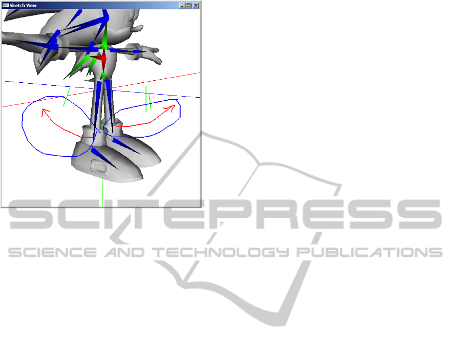
Figure 1: Sequential ordering of two motions of a character.
ject/component. The user must draw an enclosure
around a group of arrows sketches. A series of short
strokes intersecting the contour of the enclosure de-
fines the position of these animations in an animation
sequence as depicted in figure 1. Animations belong-
ing to the same enclosure are executed in parallel. A
user must be allowed to order arrows after they have
been sketched, and in particular the ordering must be
possible even after the view of the character has been
changed for sketching another animations.
We implement this idea using the overlap detec-
tion discussed in subsection 3.3. Whether or not a
stroke intersects the enclosure can easily be tested by
performing a 2D line intersection test with the stroke
and all the enclosure line segments. A sketch will be
considered to be a potential stroke if the ratio of its
bounding box is inside a defined range and its length
is shorter than a given fraction of the enclosure size.
To allow the user to coordinate the movement
of different body parts of the character model, all
sketches with the same order will be executed at the
same time. This way, a user can synchronise the
movements of limbs by arranging the order of their
sub-animations. For this to work, we need to define
fixed time slots for animating the sketches of each par-
ticular order. Thus, all animations of the same order
will be required to have the same length, which is cur-
rently 3 seconds. However, this value can be config-
ured and might have to be changed, depending on the
type of animation a user wants to sketch.
4 USER STUDY
The usability of the sketch-based animation prototype
was evaluated in a user study with 11 participants.
The majority of them were students. Seven partici-
pants were between 20 and 30 years old, and the rest
older. Due to the small sample size, the results de-
duced from this study are only indicative and serve as
a pilot study. For this user study, a list of commands
and instructions were provided to the participants to
gain a basic understanding of the use of the applica-
tion. Each participant had to solve seven tasks:
1. Use a single-headed arrow to define an arm mo-
tion of the character.
2. Use a double-headed arrow to define a repeated
arm motion of the character.
3. Use double-headed arrows to define a walking
motion of the character’s legs. Translation of the
character is not required.
4. Use a motion path to translate the character.
5. Use a circular motion path to move the character
around a circle.
6. Create a walking simulation by using a motion
path and animating the legs of the character.
7. Use animation ordering to put animations of two
different arms in a sequence, with one arm move-
ment performed after the other.
Experiment 1 and 2 were designed to find out
whether our basic sketching metaphors are intuitive
and easy to use for animation. We recorded for all
experiments any problems participants had with iden-
tifying and specifying the correct viewpoint (track-
ball rotation) for drawing an animation sketch, and
whether the correct functionality was chosen. Exper-
iment 3 was designed to find out whether animations
with multiple arrows and different rotation axes are
more difficult. Experiment 4 and 5 were designed to
assess the ease of use of the motion path metaphor,
and whether specifying a desired configuration causes
problems. Experiment 6 was designed to determine,
whether more strokes and metaphors influence the
difficulty in sketching animations. Finally, Experi-
ment 7 tests the intuitiveness of our tool for sequenc-
ing animations.
For all tasks we measured the time required for
completion and recorded any problems. After the us-
ability test, participants were given a post-study ques-
tionnaire for a qualitative assessment. The question-
naire consisted of free-form questions and statements
with answers on a seven-level Likert scale.
GRAPP 2011 - International Conference on Computer Graphics Theory and Applications
250
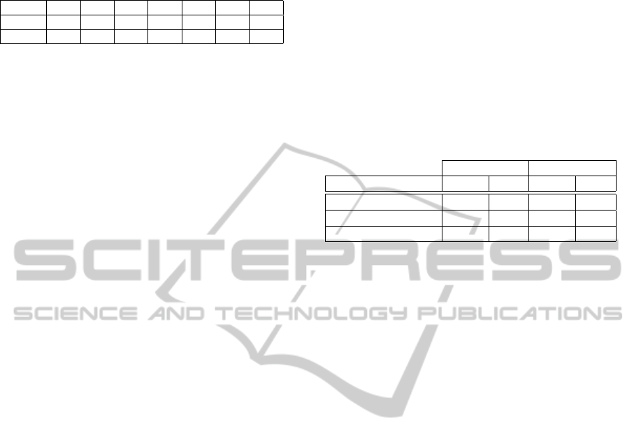
Table 1: Average completion time in minutes for each task
in the user study.
Task 1 2 3 4 5 6 7
Mean 2.45 2.77 4.60 2.13 2.27 3.40 3.00
Median 1.50 1.50 3.50 1.50 1.50 3.00 3.50
5 RESULTS
The time each participant required to complete the ex-
periments was recorded in 30 seconds intervals (0.5
minutes). Table 1 shows the mean and median time
we measured for each task.
The measurements for task 1 and 2 suggest that
the arrow metaphor is intuitive and easy to use. No
differences were observed for single and repeated mo-
tions (single-headed vs. double-headed arrows). Both
motion path experiments were also completed in a rel-
atively short time, which implies that it does not mat-
ter whether a user has to draw a random or a specific
path. Some problems were experienced with selecting
the correct bone of a character, but users usually fig-
ured this out with some trial and error. No quantitative
assessment of the precision of a task was performed
because of the inherent inaccuracies of mouse input
for sketching.
Table 1 shows that Task 3 has the highest mean
and median time. This was partially due to problems
with rotating the character and selecting the correct
limb. However, the main factor was that participants
were unaware that the initial direction of a repeated
motion is determined by which head of the double-
headed arrow is drawn first. Thus, several partici-
pants created animations in which both legs moved
synchronously. Task 6 required quite a long time, but
no particular additional problems were observed. The
main reason for the recorded time was the complexity
of the task which required rotations and zooms in or-
der to draw the required arrows for bone animations
and motion paths. The time measurements for Task
7 indicate that participants had problems creating or-
dered animations. This was expected to be the least
intuitive sketching metaphor. A common problem
was that users drew enclosures around bones rather
than around the arrows.
5.1 Questionnaire
We measured the participants’ perception of the intu-
itiveness and effectiveness of different sketched an-
imation controls using statements rated on a seven
level Likert scale ranging from “-3” (strong disagree-
ment) to “3” (strong agreement).
For each of the three animation controls “Ar-
rows for joint rotation”, “Arrows for motion path”,
“Sequencing of animations” responses were recorded
for statements regarding intuitiveness and satisfaction
with the achieved results. For example, in order to
evaluate the intuitiveness of arrows for joint rotation
we used the statement “Arrows were an intuitive way
to specify bone rotations around a joint”.
Table 2: Participant ratings of the intuitiveness and effec-
tiveness of different sketch-based animation controls [“-3”
(lowest) to “3” (highest)].
Intuitiveness Effectiveness
Animation Control Mean σ Mean σ
Joint Rotation 0.27 1.85 0.45 1.69
Sequencing 0.18 1.72 0.45 1.57
Motion Path 0.82 2.36 0.91 1.45
Table 2 indicates that overall the sketch-based an-
imations were regarded only as slightly intuitive and
effective, with the motion path sketch tool achieving
the highest score and the sequencing tool achieving
the lowest score. The results were surprisingly di-
verse, although users with previous experience with
modelling tools seemed to give higher scores (not
enough demographic data was recorded to confirm
this). One surprising result was that the motion path
had the highest standard derivation, i.e., the strongest
difference in ratings. We suspect that this might have
to do with the required change in perspective and
zoom factor for drawing the motion path, and pos-
sibly with the lack of rendering of a ground plane.
Subsequent interviews with participants revealed that
some confusion existed between synchronisations of
motions (e.g., when drawing double-headed arrows)
and sequencing of motions. Also some users re-
marked they would have preferred more control about
synchronisation and sequencing of motions, e.g., by
clicking on a component to temporarily stop its mo-
tion. Overall, the participants’ opinion regarding the
ease-of-use of the application was slightly negative
(Mean -0.64, Standard Deviation 1.86). This seems to
contradict the results of the two previous questions, as
they indicated that the metaphors are moderately intu-
itive, and the tool is moderately effective in translating
sketches into the desire animation.
For a possible explanation consider the follow-
ing user comments (number of responses in brackets).
Positive aspects were: viewport control (3), simple
animation definition (4), motion path (1), and intuitive
(1). Negative aspects were: unintended animation (3),
poor sketch recognition (3), no undo function (4), no
scroll wheel for zooming (2), lack of animation syn-
chronization (1), need to rotate camera to animate (1).
SKETCHED INTERACTION METAPHORS FOR CHARACTER ANIMATION
251

6 CONCLUSIONS
We have presented a novel tool for defining mod-
erately complex animations using sketch input. For
sketch recognition, our main animation metaphor, ar-
rows, are correctly mapped to the bones that the user
intends to move. In the resulting animation the bone
is rotated until it reaches the tip of the drawn arrow.
However, this approach has some draw-backs, as the
user is required to always move the camera to a per-
pendicular viewing direction, before sketching an an-
imation. Overall the animation controls were per-
ceived as moderately intuitive and effective, but the
perception of the ease-of-use of the application was
slightly negative. The small sample size of the user
study and insufficient demographic data did not allow
us to make statements about how perception of the
tool differs between experienced and inexperienced
computer users. A positive aspect of the application is
that the animation controls are applied to object com-
ponents connected by joints and can hence be used
for a wide range of applications such as computer
generated characters, robots and machinery. A more
detailed discussion is given in (Schauwecker et al.,
2011). Future work includes an improved sketch
recognition, and giving users more control about the
range of motions and their synchronisation and se-
quencing.
REFERENCES
Au, O. K.-C., Tai, C.-L., Chu, H.-K., Cohen-Or, D., and
Lee, T.-Y. (2008). Skeleton extraction by mesh con-
traction. In SIGGRAPH ’08: ACM SIGGRAPH 2008
papers, pages 1–10, New York, NY, USA. ACM.
Baran, I. and Popovi
´
c, J. (2007). Automatic rigging and
animation of 3d characters. ACM Trans. Graph.,
26(3):72. http:// www.mit.edu/ ∼ibaran/ autorig/.
Bourke, P. (2009). The shortest line between two lines in 3d.
http://local.wasp.uwa.edu.au/∼pbourke/geometry/
lineline3d/.
Cornea, N., Silver, D., Yuan, X., and Balasubramanian, R.
(2005). Computing hierarchical curve-skeletons of 3d
objects. The Visual Computer, 21(11):945–955.
Eberly, D. (2009). Minimum-area rectangle containing
a convex polygon. http:// www.geometrictools.com/
Documentation/ MinimumAreaRectangle.pdf.
Igarashi, T., Moscovich, T., and Hughes, J. F. (2005). As-
rigid-as-possible shape manipulation. ACM Trans.
Graph., 24(3):1134–1141.
Kavan, L., Collins, S.,
ˇ
Z
´
ara, J., and O’Sullivan, C. (2007).
Skinning with dual quaternions. In I3D ’07: Proceed-
ings of the 2007 symposium on Interactive 3D graph-
ics and games, pages 39–46, New York, NY, USA.
ACM.
Lambert, T. (2009). Gift wrapping algorithm. http://
www.cse.unsw.edu.au/∼lambert/java/3d/
giftwrap.html.
Li, Q., Geng, W., Yu, T., Shen, X., Lau, N., and Yu, G.
(2006). MotionMaster: authoring and choreographing
Kung-fu motions by sketch drawings. In Proceedings
of the 2006 ACM SIGGRAPH/Eurographics sympo-
sium on Computer animation, page 241. Eurographics
Association.
Liu, P., Wu, F., Ma, W., Liang, R., and Ouhyoung, M.
(2003). Automatic animation skeleton construction
using repulsive force field. In Pacific Graphics, pages
409–413. Citeseer.
Mao, C., Qin, S. F., and Wright, D. (2007). Sketch-based
virtual human modelling and animation. In SG ’07:
Proceedings of the 8th international symposium on
Smart Graphics, pages 220–223. Springer-Verlag.
Microsoft (2010). Ink Analysis Overview.
http://msdn.microsoft.com/en-us/library/
ms704040(VS.85).aspx.
Owen, G. S. (2009). 3d rotation. http:// www.siggraph.org/
education/materials/HyperGraph/modeling/
mod
tran/ 3drota.htm.
Sakamoto, D., Honda, K., Inami, M., and Igarashi, T.
(2009). Sketch and run: a stroke-based interface for
home robots. In CHI ’09: Proceedings of the 27th in-
ternational conference on Human factors in comput-
ing systems, pages 197–200. ACM.
Schauwecker, K., van den Hurk, S., Yuen, W., and
W
¨
unsche, B. C. (2011). Sketched interac-
tion metaphors for character animation. Graph-
ics group technical report #2011-001, Department
of Computer Science, University of Auckland.
http://www.cs.auckland.ac.nz/∼burkhard/Reports/
GraphicsGroupTechnicalReport2011 001.pdf.
Steger, E. (2004). Sketch-based animation language. http://
www.cs.toronto.edu/∼esteger/sketchlang/index.html.
Thorne, M., Burke, D., and van de Panne, M. (2004).
Motion doodles: an interface for sketching charac-
ter motion. ACM Transactions on Graphics (TOG),
23(3):424–431.
GRAPP 2011 - International Conference on Computer Graphics Theory and Applications
252
