
DECENTRALISED ORCHESTRATION OF SERVICE-ORIENTED
SCIENTIFIC WORKFLOWS
Adam Barker
School of Computer Science, University of St Andrews, St Andrews, U.K.
Rajkumar Buyya
Cloud Computing and Distributed Systems (CLOUDS) Laboratory
Department of Computer Science and Software Engineering, University of Melbourne, Melbourne, Australia
Keywords:
Service-oriented architectures, Optimisation, Scientific workflows, Data deluge.
Abstract:
Service-oriented workflows in the scientific domain are commonly composed as Directed Acyclic Graphs
(DAGs), formed from a collection of vertices and directed edges. When orchestrating service-oriented DAGs,
intermediate data are typically routed through a single centralised engine, which results in unnecessary data
transfer, increasing the execution time of a workflow and causing the engine to become a performance bot-
tleneck. This paper introduces an architecture for deploying and executing a service-oriented DAG-based
workflows across a peer-to-peer proxy network. A workflow is divided into a set of vertices, disseminated
to a group of proxies and executed without centralised control over a peer-to-peer proxy network. Through
a Web services implementation, we demonstrate across PlanetLab that by reducing intermediate data transfer
and by sharing the workload between distributed proxies, end-to-end workflows are sped up. Furthermore, our
architecture is non-intrusive: Web services owned and maintained by different institutions do not have to be
altered prior to execution.
1 INTRODUCTION
Service-oriented architectures are an architectural
paradigm for building software applications from a
number of loosely coupled distributed services. This
paradigm has seen wide spread adoption through the
Web services approach, which has a suite of core stan-
dards (e.g., XML, WSDL and SOAP) to facilitate in-
teroperability.
These core standards however do not provide the
rich behavioural detail necessary to describe the role
an individual service plays as part of a larger, more
complex collaboration. Co-ordination of services is
often achieved through the use of workflow tech-
nologies. As defined by the ‘Workflow Management
Coalition’ (Hollingsworth, 1995), a workflow is the
automation of a business process, in whole or part,
during which documents, information or tasks are
passed from one participant (a resource, either human
or machine) to another for action, according to a set
of procedural rules.
Workflows in the scientific community (Barker
and van Hemert, 2008) are commonly modelled as
Directed Acyclic Graphs (DAGs), formed from a col-
lection of vertices (units of computation) and directed
edges. The Genome Analysis and Database Update
system (GADU) (Sulakhe et al., 2008), the South-
ern California Earthquake Centre (SCEC) (Deel-
man and et al., 2006) CyberShake project, and the
Laser Interferometer Gravitational-Wave Observatory
(LIGO) (Taylor et al., 2006) are examples of High
Performance Computing applications composed us-
ing DAGs. DAGs present a dataflow view, here data
is the primarily concern, workflows are constructed
from processing vertices and data transport edges.
Taverna (Oinn and et al, 2004) is an example of a
popular graphical Web service composition tool used
primarily in the life sciences community in which
workflows are represented as DAGs. Graph vertices
can be one of a set of service types: WSDL Web ser-
vices, BeanShell (lightweight scripting for Java) com-
ponents, String constants etc. Services are given in-
put and output ports which correspond to individual
input and output variables. Edges are then formed by
connecting services together by mapping output ports
with input ports.
222
Barker A. and Buyya R..
DECENTRALISED ORCHESTRATION OF SERVICE-ORIENTED SCIENTIFIC WORKFLOWS.
DOI: 10.5220/0003384302220231
In Proceedings of the 1st International Conference on Cloud Computing and Services Science (CLOSER-2011), pages 222-231
ISBN: 978-989-8425-52-2
Copyright
c
2011 SCITEPRESS (Science and Technology Publications, Lda.)
1.1 Motivating Scenario: Calculating
Redshift
At this point, in order to put our motivation and prob-
lem statement into perspective, it is useful to con-
sider an illustrative scenario. The Redshift scenario
is taken from the AstroGrid (Allan et al., 2010) (UK
e-Research project) science use-cases and involves re-
trieving and analysing data from multiple distributed
resources. This scenario is representative of a class of
large-scale scientific workflows, where data and ser-
vices are made available through a Web service. It
will be referenced throughout the remainder of this
paper. Figure 1 is a representation of the AstroGrid
redshift scenario in Taverna.
Photometric Redshifts use broad-band photome-
try to measure the Redshifts of galaxies. While photo-
metric Redshifts have larger uncertainties than spec-
troscopic Redshifts, they are the only way of de-
termining the properties of large samples of galax-
ies. This scenario describes the process of querying
a group of distributed databases containing astronom-
ical images in different bandwidths, extracting ob-
jects of interest and calculating the relative Redshift
of each object.
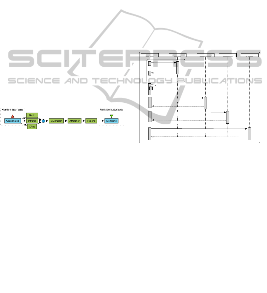
Figure 1: AstroGrid scenario – Taverna representation.
Workflow inputs are the RA and DEC coordinates, services
are represented as rectangles, links correspond to the flow
of data between services.
The scenario represents a workflow and begins
with a scientist inputting the RA (right ascension) and
DEC (declination) coordinates into the system, which
define an area of sky. These coordinates are used as
input to three remote astronomical databases; no sin-
gle database has a complete view of the data required
by the scientist, as each database only stores images
of a certain waveband. At each of the three databases
the query is used to extract all images within the
given coordinates which are returned to the scientist.
The images are concatenated and sent to the SExtrac-
tor (Bertin and Arnouts, ) tool for processing. SEx-
tractor scans each image in turn and uses an algorithm
to extract all objects of interest (positions of stars,
galaxies etc.) and produces a table for each of the
wavebands containing all the data. A cross matching
tool is then used to scan all the images and produce
one table containing data about all the objects of inter-
est in the sky, in the five wavebands. This table is
then used as input to the HyperZ
1
algorithm which
computes the photometric Redshifts and appends it to
each value of the table used as input. This final table
consists of multi-band files containing the requested
position as well as a table containing for each source
all the output parameters from SExtrator and HyperZ,
including positions, magnitudes, stellar classification
and photometric Redshifts and confidence intervals;
the final table is returned to the user.
1.2 Problem Statement
Although service-oriented workflows can be com-
posed as DAGs using a dataflow model, in reality
they are orchestrated from a single workflow engine,
where intermediate data are typically routed through
a centralised engine.
Source
SExtractor XMatcher
HyperZ
Engine
FOR EACH SOURCE
retrieve(RA, DEC)
images
extractObjects (images)
VO_Tables: objects
XMatch (VO_Tables: objects)
VO_Table: combined
HyperZ (VO_Table: combined)
VO_Table: multi_band
concat (images)
Figure 2: UML Sequence diagram: AstroGrid scenario.
Figure 2 is a UML Sequence diagram displaying
how the AstroGrid workflow is orchestrated. The ini-
tial RA and DEC coordinates are used as input to
each of the three source databases: Radio, Infrared
and XRay. Each source database then returns a set
of images to the workflow engine. These images are
then combined and passed through the SExtractor,
XMatcher and HyperZ services. Finally, the HyperZ
service returns the Multiband table as output.
In the AstroGrid scenario, output from each of
the source databases and processing services passes
via the workflow engine, in order to be passed to the
next service in the workflow chain. When one is or-
chestrating Web services from a tool such as Taverna,
the workflow engine becomes a bottleneck to the per-
formance of a workflow. Large sets of intermediate
data which are consistent with scientific workflows
are routed via the workflow engine, which results in
unnecessary data transfer, increasing the execution
1
http://webast.ast.obs-mip.fr/hyperz/
DECENTRALISED ORCHESTRATION OF SERVICE-ORIENTED SCIENTIFIC WORKFLOWS
223
time of a workflow and causing the engine to become
a bottleneck to the execution of an application.
1.3 Paper Contributions and Structure
This paper proposes a novel architecture for accelerat-
ing end-to-end workflows by deploying and executing
a service-oriented workflow (composed as a DAG)
across a peer-to-peer proxy network. Individual prox-
ies are deployed at strategic network locations in or-
der to exploit connectivity to remote Web services.
By ‘strategic’ we could refer to one of many factors
including network distance, security, policy etc. Prox-
ies together form a proxy network which facilitate a
number of functions such as service invocation, rout-
ing of intermediate data and data caching.
By breaking up a workflow and disseminating it
across a peer-to-peer network, workflow bottlenecks
associated with centralised orchestration are partially
removed, intermediate data transfer is reduced, by
sharing the workflow across distributed proxies and
applications composed of interoperating Web services
are sped up.
Importantly, our proposed architecture is a non-
intrusive solution, Web services do not have to be
redeployed or altered in any way prior to execution.
Furthermore, a DAG-based workflow defined using a
visual composition tool (e.g., Taverna) can be simply
translated into our DAG-based workflow syntax and
automatically deployed across a peer-to-peer proxy
network.
A Java Web services implementation serves as
the basis for performance analysis experiments con-
ducted over PlanetLab (Chun et al., 2003). These
experiments empirically demonstrate how our pro-
posed architecture can speed up the execution time
of a workflow when compared to standard orchestra-
tion. Although this paper focuses on Web services,
the concept is generic and can be applied to other
classes of application, i.e., High Performance Com-
puting, Cloud Computing etc.
This paper is structured as follows: Section 2 in-
troduces the architecture of an individual proxy and
multiple proxies which together form a proxy net-
work. A syntax is introduced for service-oriented
DAG-based workflows and the algorithms which di-
vide a workflow, assign and enact a workflow across
a proxy network are described. A Java Web services
implementation, which serves as a platform for per-
formance analysis is also discussed. Section 3 de-
scribes the performance analysis experiments. Re-
lated work is discussed in Section 4. Finally conclu-
sions and future work are addressed in Section 5.
2 PROXY ARCHITECTURE
Within our architecture a proxy is a middleware com-
ponent that is deployed at a strategic location to a Web
service or set of Web services. For the purposes of
this paper, by strategic we mean in terms of network
distance; as closely as possible to an enrolled ser-
vice, i.e., on the same Web server or within the same
domain, such that communication between a proxy
and a Web service takes place over a local, not Wide
Area Network. Proxies are considered to be volunteer
nodes and can be arbitrarily sprinkled across a net-
work, importantly not interfering with currently de-
ployed infrastructure.
A proxy is generic and can concurrently execute
any workflow definition. In order for this to be possi-
ble, the workflow definition is treated as an executable
object which is passed between proxies in a proxy net-
work. Proxies invoke Web services on behalf of the
workflow engine, storing any intermediate data at the
proxy. Proxies form peer-to-peer proxy networks and
can route data directly to one another, avoiding the
bottleneck problems associated with passing interme-
diate data through a single, centralised workflow en-
gine.
Translation
WF Editor
W,V
W,V
W,V
W,V
W,V
Scheduler
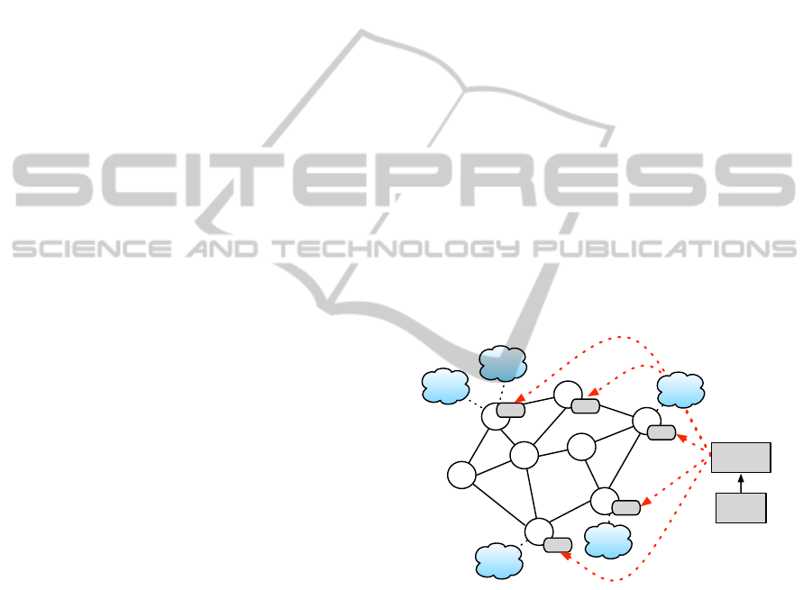
Figure 3: Proxy architecture: Web services represented by
clouds, proxies by circles, the workflow definition and ver-
tex (W,V) by a rounded rectangle.
Figure 3 shows a high level architectural diagram
of a proxy network. A user designs a service-oriented
DAG-based workflow using a visual workflow edi-
tor such as Taverna. A scheduling service assigns
workflow vertices to proxies, the unique identifier of
each proxy is then spliced into the workflow defini-
tion. Each proxy then is passed an entire copy of the
workflow definition. Once a proxy receives the work-
flow definition, it executes its assigned set of vertices
(once all dependencies are resolved) and passes any
intermediate data according to the directed edge defi-
nition. Once deployed a DAG-based workflow is ex-
CLOSER 2011 - International Conference on Cloud Computing and Services Science
224

ecuted without any centralised control over a peer-to-
peer proxy network.
The following subsections describe in detail how a
user designs a workflow, how the workflow definition
is divided and assigned to a set of proxies, deployed
across a proxy network and enacted.
2.1 Workflow Definition
A workflow is specified as a DAG according to the
syntax displayed in Figure 4. It is important to note
that the DAG syntax is not a novel contribution of
this paper, it is primarily a way to describe the al-
gorithms and architecture of our proposed approach.
We have taken inspiration from the Taverna SCUFL
language (Oinn and et al, 2004), our syntax is a sim-
plified version which does not support the additional
processor types such as BeanShell etc. A workflow
relies on static binding at deployment time, dynamic
binding methods are left to future research.
Workflow ::= ID
w
, {Vertex}, {Edge}, ID
s
Vertex ::= vertex(ID
v
, Processor)
Processor ::= WS | Input | Output
WS ::= s(Config
(k)
, {Inport}, {Outport}, ID
p
)
Input ::= input(value, Outport)
Output ::= output(value, Inport)
Inport ::= in(ID
in
, Type, [digit])
Outport ::= out(ID
out
, Type)
ID ::= ID
w
| ID
s
| ID
v
| ID
p
| ID
in
| ID
out
Type ::= XML RPC Types
Config ::=
h
name, value
i
Edge ::= ID
v
:ID
out
→ {ID
v
:ID
in
}
Figure 4: Workflow definition syntax.
A workflow is labelled with a unique identifier
ID
w
and consists of a set of vertices {Vertex} and
a set of edges {Edge}. A vertex is given a globally
unique identifier ID
v
and can consist of one of a set
of processor types. As this paper focuses on service-
oriented workflows, processors are Web service defi-
nitions WS or input and output variables.
A Web service is defined firstly as a list of con-
figuration pairs Config
(k)
which are simply
h
name,
value
i
pairs and define the information necessary to
invoke an external Web service: WSDL location, op-
eration name etc. Secondly, a set of input ports
{Inport}; each inport is given a unique identifier
within a processor ID
in
and a Type definition, types
map to the standard set of XML RPC Types
2
. The
final parameter (optional) defines how many inputs
are expected at a given inport. A set of output ports
2
http://ws.apache.org/xmlrpc/types.html
{Outport}; each outport is given a unique identifier
within a processor ID
out
and a Type definition. The
final parameter of a processor is ID
p
, which repre-
sents the globally unique identifier (mapping to an in-
dividual IP address) of a proxy which is executing a
given vertex; these are initially null and spliced in
before the workflow definition is disseminated to a set
of proxies. Proxy identifiers are included in the work-
flow definition so that individual proxies can commu-
nicate with one another when executing a workflow.
ID
s
, the final parameter of a Workflow definition is the
location (IP address) of the scheduling service, this is
also spliced in before the workflow is disseminated so
that the final output from a workflow can be passed
back to the user.
The final processor types supported are Input
(used as input to a Web service) and Output variables
(used as output from a Web service). An Input vari-
able is defined as a value, which is the actual value
assigned to the variable and an outport definition. An
Output variable is defined as a value, which is ini-
tially a wildcard and an inport definition. The Types
supported are the same set of XML RPC types.
In order to complete the workflow, a set of di-
rected edges are formed which constitute a dataflow
mapping from processor inports to processor outports.
This is specified by providing the following map-
ping: ID
v
:ID
out
→ {ID
v
:ID
in
}. The types of the
outport to inport mappings must match and are en-
forced by the workflow editor.
2.2 Example Definition
Figure 5 is a representation of the AstroGrid scenario
in the workflow definition syntax, Figure 6 is a cor-
responding diagrammatic representation. With ref-
erence to Figure 5, within the scope of the work-
flow identifier calculate redshift, eight vertices
are defined: ra, dec represent the workflow input pa-
rameters, the variables are defined by the physical val-
ues which are transferred via the outports ra output
and dec output. As the workflow output needs to be
written back to a user’s desktop, the vertex wf o repre-
sents the final workflow output which will eventually
be written to the inport multi band; this output will
then be passed back to the scheduling service which
initiated the workflow.
The remaining vertices are WS definitions, radio,
infra and xray are the distributed data sources, con-
taining data from each of the required wave lengths;
tools represents the co-located services SExtractor
and XMatcher; finally z is the HyperZ processing ser-
vice. Each of the service definitions contains typed
inport and outport definitions; note the 3 in the tools
DECENTRALISED ORCHESTRATION OF SERVICE-ORIENTED SCIENTIFIC WORKFLOWS
225
calculate_redshift,
//RA, DEC and Output Vertices
{vertex(ra, input(100, {out(ra_output, String)})),
vertex(dec, input(50, {out(dec_output, String)})),
vertex(wf_o, output(_, {in(multi_band, Object[])})),
//Source Vertices
vertex(radio, s(config, {in(ra_input, String),
in(dec_input, String)}, {out(image_set, byte[])}, _)),
vertex(infra, s(config, {in(ra_input, String),
in(dec_input, String)}, {out(image_set, byte[])}, _)),
vertex(xray, s(config, {in(ra_input, String),
in(dec_input, String)}, {out(image_set, byte[])}, _)),
//Processing Vertices
vertex(tools, s(config, {in(images, byte[], 3)},
{out(combined, Object[])}, _)),
vertex(z, s(config, {in(combined, Object[])},
{out(multi_band, Object[])})), _},
//Edge definitions
{ra:ra_output -> radio:ra_input, infra:ra_input,
xray:ra_input,
dec:dec_output -> radio:dec_input, infra:dec_input,
xray:dec_input,
radio:image_set -> tools:images,
infra:image_set -> tools:images,
xray:image_set -> tools:images,
tools:combined -> z:combined,
z:multi_band -> wf_o:multi_band}, _
Figure 5: AstroGrid scenario workflow definition.
inport images states that 3 inputs (which will be
merged) are required, for simplicity config repre-
sents the concrete details of individual Web services.
The wildcard at the end of each service definition is
the unique identifier of the proxy ID
p
which is spliced
in before the workflow definition is disseminated to
a set of proxies. A set of Edge definitions connect
vertex outports with vertex inports according
to the flow of data in the AstroGrid scenario.
2.3 Web Services Implementation
The proxy architecture is available as an open-source
toolkit implemented using a combination of Java (ver-
sion 1.6) and Apache Axis (version 2) Web ser-
vices (Apache Axis, ), it consists of the following core
components:
• Registry Service. When a proxy is deployed it
is automatically enrolled with the registry service,
which contains global knowledge of distributed prox-
ies. The registry service logs data of previous suc-
cessful interactions and proxies are polled to ensure
availability.
Radio
Infra
XRay
Tools
HyperZ
radio
infra
xray
tools
RA DEC
WF_O
Z
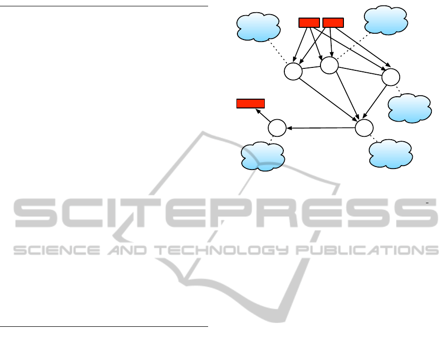
Figure 6: Possible proxy configuration for the AstroGrid
scenario: Edges are directed and show dataflow between
proxies. Workflow inputs (RA, DEC) and outputs (WF O)
are also labelled. For simplicity, tools represents the co-
located services SExtractor and XMatcher. Workflow en-
gine and scheduling service not shown.
• XML Syntax. The workflow syntax displayed in
Figure 4 is encoded in XML, allowing the registry
service to splice in the proxy identifiers and proxies.
Type checking between outport and inport definitions
is enforced at the syntax level.
• Translation. A translation component automat-
ically converts workflows defined in the Taverna
SCUFL dataflow language into our workflow specifi-
cation syntax. Translations from other languages are
possible, we have chosen Taverna SCUFL as it is a
widely accepted platform, particularly in the life sci-
ences community.
• Scheduling Service. Once a user has designed a
workflow and it has been translated, the scheduling
service (a local component) takes as input the work-
flow definition and consults the registry service, splic-
ing in a unique proxy identifier for every vertex in a
workflow definition. The scheduling service’s IP ad-
dress is spliced into the workflow definition, so that
final output can be sent back to the user.
• Proxy. Proxies are made available through a stan-
dard WSDL interface, allowing them to be simply
integrated into any standard workflow tool. As dis-
cussed further in Section 2.5, a proxy has two re-
mote methods: initiate to instantiate a proxy with a
workflow and a vertex, and data, allowing proxies to
pass data to one another, which in our implementation
is via SOAP messages over HTTP. Proxies are simple
to install and configure and can be dropped into an
AXIS container running on an application server, no
specialised programming needs to take place in order
to exploit the functionality.
CLOSER 2011 - International Conference on Cloud Computing and Services Science
226

2.4 Workflow Deployment and Vertex
Assignment
For simplicity in the algorithm definition, we assume
reliable message passing and service invocation, how-
ever, fault tolerance has been built into the corre-
sponding Web services implementation. A proxy is
generic and can concurrently execute any vertex from
any workflow definition. In order for this to be possi-
ble, the workflow definition is treated as an executable
object, which is passed between proxies in a proxy
network. The workflow definition is passed to the
scheduling service which needs to assign proxies to
vertices. This process is formally defined by Algo-
rithm 1.
Algorithm 1: Vertex assignment.
1: for each Vertex ID
v
where ID
v
∈ {Vertex} do
2: if (Processor = WS) then
3: ID
p
← locate(ID
v
, WS)
4: WS.ID
p
← ID
p
5: {
h
ID
v
, ID
p
i
} ← {
h
ID
v
, ID
p
i
} + ID
v
, ID
p
6: end if
7: end for
8: for each Vertex ID
v
where ID
v
∈ {
h
proxy, ID
v
i
} do
9: initiate(Workflow, ID
v
)
10: end for
All proxies are enrolled with the registry service,
which is a global directory of each proxy within the
system. For each ID
v
in {Vertex} a suitable proxy
must be located, if the processor type is a service
definition, i.e., not an input or output variable. In
our existing implementation, the registry service se-
lects ‘suitable’ proxies which are deployed with the
same network domain as the WS it will eventually
invoke. However, we are investigating optimisation
techniques which will be addressed by further work,
discussed in more detail in Section 5.
This suitability matching is performed by the
scheduling service which in turn consults with the
registry service. The scheduling service invokes the
locate method on the registry service, which takes as
input a vertex ID
v
and a WS definition and returns the
unique identifier of a proxy which will enact a given
vertex ID
v
. This identifier is then spliced into the
processor definition; before the assignment process
begins all ID
p
definitions are wildcards, each vertex
(multiple vertices can be assigned to the same proxy)
is then assigned before the workflow is disseminated.
The proxy identifier is added so that proxies can com-
municate throughout the system globally.
The proxy identifier along with the vertex identi-
fier are added to a set. Once the proxy assignment
process is complete, the workflow definition and ver-
tex a proxy is to assume ID
v
is sent to each proxy
in the set {
h
ID
v
, proxy
i
}. The remote method
initiate is invoked on each proxy.
2.5 Workflow Execution
A proxy can concurrently execute any vertex from any
workflow. With reference to Algorithm 2, in order to
initiate a workflow, the remote method initiate is
invoked on each proxy, given a workflow definition
and ID
v
. The vertex definition ID
v
is extracted from
the workflow. If the vertex relies on data from other
vertices, it must wait until all inports have been re-
solved. Therefore, each inport ID
in
in {Inport} must
be resolved before execution of ID
v
can begin. This
is achieved through the internal method resolve in
which checks if data for a given inport has been re-
ceived; if the inport vertex definition is simply an
input variable then the corresponding value is re-
trieved.
Algorithm 2: Vertex enactment.
1: initiate(Workflow, ID
v
)
2: for each Inport ID
in
where ID
in
∈ {Inport} do
3: resolve in(ID
in
)
4: end for
5: {input} ← get input(ID
w
, ID
v
)
6: results ← invoke({config}, {input})
7: for each Outport ID
out
where ID
out
∈ {Outport} do
8: {ID
v
:ID
in
} ← resolve out(ID
v
:ID
out
, {Edge})
9: for each Vertex ID
v
where ID
v
∈ {ID
v
:ID
in
} do
10: if (Processor = WS) then
11: ID
p
← WS.ID
p
12: data(ID
w
, ID
in
, results)
13: delete(results)
14: else if (Processor = Output) then
15: value ← results
16: data(ID
w
, ID
s
, results)
17: end if
18: end for
19: end for
Once all inport dependencies have been resolved,
given the unique workflow identifier ID
w
and ID
v
, the
input data set {input} is retrieved through the inter-
nal method get input. The proxy takes the WSDL
location, operation name and other parameters de-
fined in {config} and dynamically invokes the ser-
vice using {input} as input to the Web service. Re-
sults are then stored locally at the proxy.
In order to determine where (i.e., which proxy)
to send the output of a given service invocation, the
{Edge} set is inspected which contains mappings
from a vertex outport to a set of vertex inports. The
set of inports which map to a corresponding outport
is returned by the internal resolve
out method. In
order to determine which proxy to send these data to,
each vertex in this set is traversed and the location of
DECENTRALISED ORCHESTRATION OF SERVICE-ORIENTED SCIENTIFIC WORKFLOWS
227
the proxy, ID
p
is retrieved from the workflow defini-
tion.
The remote method data is invoked on the proxy
ID
p
, using the workflow identifier ID
w
, the inport
identifier ID
in
and the result data as input. Once re-
ceived (confirmed by an acknowledgement) by the re-
cipient proxy, these data are stored according to ID
w
and ID
in
and deleted from the sender proxy. If the out-
port corresponds to a output, this variable is written
back to the scheduling service ID
s
, which is running
on a user’s desktop. This process is repeated for each
outport.
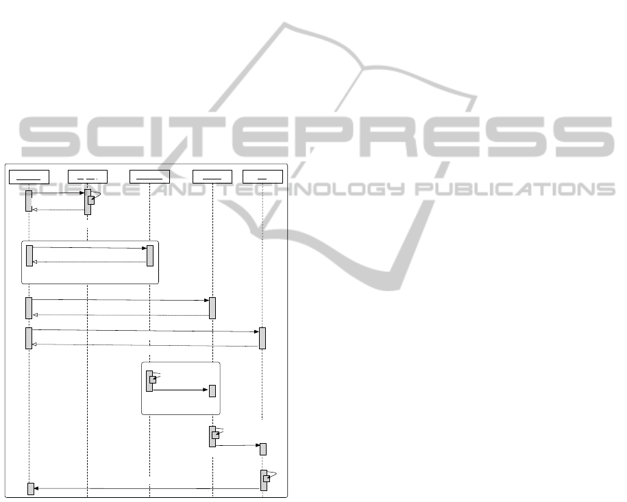
2.6 End-to-end Example
Figure 7 is a UML Sequence diagram which demon-
strates the interaction between the scheduling service,
registry service and the set of proxies in the AstroGrid
scenario.
P: sources
P: tools
P: z
Scheduler
Registry
assign
FOR EACH SOURCE
FOR EACH SOURCE
initiate(W,source_type)
ack
initiate(W,tools)
ack
resolve_in
invoke
resolve_out
data(images)
resolve_in
invoke
resolve_out
data(combined)
resolve_in
invoke
resolve_out
data(multi_band)
initiate(W,z)
ack
locate(IDv, WS)
FOR EACH VERTEX
IDp
Figure 7: UML Sequence diagram: AstroGrid scenario
proxy network.
3 PERFORMANCE EVALUATION
In order to validate the hypothesis that our architec-
ture can reduce intermediate data transfer and speed
up the execution time of a workflow, a set of per-
formance analysis experiments have been conducted.
Our architecture has been evaluated across Internet-
scale networks on the PlanetLab framework. Planet-
Lab is a highly configurable global research network
of distributed servers that supports the development
of new network services.
The AstroGrid scenario described throughout this
paper serves as the basis for our performance analy-
sis. This scenario is representative (in terms of data
size and topology) of a class of large-scale scientific
workflows and has been configured as follows:
• PlanetLab Deployment. Data sources are a Web
service which take as input an integer representing
how much data the service is to return; the service
then returns a Byte array of the size indicated in the
input parameter. Analysis services are simulated via
a sleep and return a set of data representative of the
given input size. These data sources and analysis ser-
vices were deployed over the PlanetLab framework.
• Workflow Engine. In order to benchmark our ar-
chitecture two configurations of the AstroGrid sce-
nario were set up: the first was executed on the com-
pletely centralised Taverna workflow (version 1.7.2)
environment, the second was the same representation
executed across a peer-to-peer proxy network accord-
ing to the implementation described in Section 2.3.
• Speedup. The mean speedup is calculated by divid-
ing the mean time taken to execute the workflow us-
ing standard orchestration (i.e., non-proxy, fully cen-
tralised) and dividing it by the mean time taken to ex-
ecute the workflow using our proxy architecture, e.g.,
a result of 1.5 means that the proxy architecture exe-
cutes 50% faster than standard orchestration.
• Proxy Configurations. Three different proxy con-
figurations are shown: “same machine”, here a proxy
is installed on the same physical machine as the Web
service it is invoking, “same domain”, the proxy is
installed on a different machine within the same net-
work domain, and “distributed” where a proxy is in-
stalled on a node within the same country as the Web
service it is invoking. In each configuration one proxy
is responsible for one service.
• Graphs. Each configuration was executed 50 times
across the PlanetLab framework. In each graph, the y-
axis displays the mean speedup ratio (along with 95%
confidence intervals from each of the 50 runs per con-
figuration) and the x-axis displays the total volume of
data flowing through the workflow. The number of
services involved is independent of the mean speedup
ratio as we have taken the mean ratio across a set of
scaling experiments: we have scaled the initial data
sources from 2 to 20 and repeated this while execut-
ing the AstroGrid DAG in reverse order. To prevent
the data processing from influencing our evaluation,
it has not been accounted for in the performance anal-
ysis experiments.
CLOSER 2011 - International Conference on Cloud Computing and Services Science
228
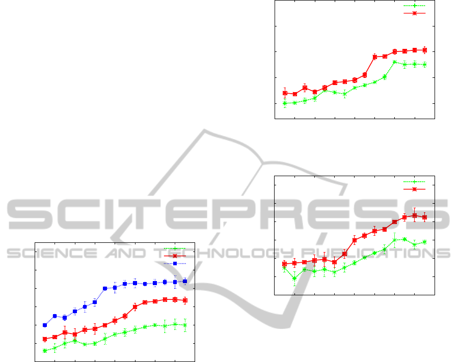
3.1 Experiment 1
Each of the data sources, analysis services and work-
flow engine were installed on separate PlanetLab
nodes in the USA. As one can see from Figure 8 in all
configurations our architecture outperforms the cen-
tralised workflow configuration. If one calculates the
average across all data points for each of the exper-
iments, the “same machine” configuration observes
a speedup of 75%, the “same domain” configuration
49% and the “distributed” configuration 30%.
As the results demonstrate, the speedup is great-
est when a proxy is deployed as closely as possible
to the back-end Web service, i.e., on the same ma-
chine. The cost of the proxy to service data move-
ment increases as the proxy moves further away from
the service it is invoking, in the “same machine” con-
figuration, the input and output of a service invoca-
tion is flowing over a LAN. However, in the most ex-
treme case, the “distributed” configuration an average
speedup of 30% is observed over all runs.
1
1.2
1.4
1.6
1.8
2
2.2
0 100 200 300 400 500 600 700 800
Mean speedup
Total data transferred (MB)
Distributed
Same domain
Same machine
Figure 8: Experiment 1 – Mean speedup.
3.2 Experiment 2
In this configuration, each of the data sources and
analysis services were deployed on separate Planet-
Lab nodes across the USA. However, the workflow
engine was now even further distributed from the ser-
vices, running from a desktop machine in Melbourne.
As one can see from Figure 9, as the cost (network
distance) increases from the workflow engine to the
workflow services, the hop any intermediate data has
to make increases in cost. As the cost of intermediate
data transport increases, the benefit of using our ar-
chitecture grows as intermediate data transport is opti-
mised. To quantify, this speedup ranged from 68% to
153% speedup for the “same domain” configuration
and 51% to 125% for the “distributed” configuration.
1.5
2
2.5
3
3.5
0 100 200 300 400 500 600 700 800
Mean speedup
Total data transferred (MB)
Distributed
Same domain
Figure 9: Experiment 2 – Mean speedup.
1
1.2
1.4
1.6
1.8
2
2.2
0 100 200 300 400 500 600 700 800
Mean speedup
Total data transferred (MB)
Distributed
Same domain
Figure 10: Experiment 3 – Mean speedup.
3.3 Experiment 3
In order to distribute the services further, the data
sources were deployed on PlanetLab nodes in the
USA, the analysis services deployed on nodes in Eu-
rope (France and Germany) and the workflow engine
was running from a desktop machine in Melbourne.
With reference to Figure 10, speedup ranged from
34% to 85% for the “same domain” configuration
and 30% to 58% for the “distributed” configuration.
In this experiment one can observe an increased cost
in distributing the workflow definition to each of the
proxies prior to enactment, demonstrated by the lack
of increase in mean speedup at lower data sizes.
4 RELATED WORK
4.1 Techniques in Data Transfer
Optimisation
In (Martin et al., 2008) the scalability argument made
in this paper is also identified. The authors propose a
DECENTRALISED ORCHESTRATION OF SERVICE-ORIENTED SCIENTIFIC WORKFLOWS
229

methodology for transforming the orchestration logic
in BPEL into a set of individual activities that coor-
dinate themselves by passing tokens over shared, dis-
tributed tuple spaces. The model suitable for execu-
tion is called Executable Workow Networks (EWFN),
a Petri nets dialect.
The concept of pointers in service-oriented archi-
tectures (Wieland et al., 2009) allows Web services to
pass data by reference rather than by value. This has
the advantage that the workow engine is disburdened
of handling all data passing between the orchestrated
Web Services, which helps to reduce network trafc
and processing time.
Service Invocation Triggers (Binder et al., 2006) is
an architecture for decentralised execution. Using the
Triggers architecture, before execution can begin the
input workflow must be deconstructed into sequen-
tial fragments, these fragments cannot contain loops
and must be installed at a trigger; this is a rigid and
limiting solution and is a barrier to entry for the use
of proxy technology. In contrast with our proxy ap-
proach nothing in the workflow has to be altered prior
to enactment.
The Flow-based Infrastructure for Composing
Autonomous Services or FICAS (Liu et al., 2002) is a
distributed data-flow architecture for composing soft-
ware services. FICAS is intrusive to the application
code as each application that is to be deployed needs
to be wrapped with a FICAS interface.
In (Chafle et al., 2004), an architecture for decen-
tralised orchestration of composite Web services de-
fined in BPEL is proposed. Our research deals with
a set of challenges not addressed by this architecture:
how to optimise service-oriented DAG-based work-
flows, how to automatically deploy a workflow across
a set of volunteer proxy nodes given a workflow topol-
ogy, where to place proxies in relation to Web ser-
vices, how these concepts operate across Internet-
scale networks.
In previous work (Barker et al., 2008b) (Barker
et al., 2008a) we proposed Circulate, a proxy-based
architecture based on a centralised control flow, dis-
tributed data flow model. This paper has focused on
executing DAG-based workflows without centralised
control and explored a richer set of proxy functional-
ity.
4.2 Third-party Data Transfers
This paper focuses primarily on optimising service-
oriented workflows, where services are: not equipped
to handle third-party transfers, owned and maintained
by different organisations, and cannot be altered in
anyway prior to enactment. For completeness it is
important to discuss engines that support third-party
transfers between nodes in task-based workflows.
Directed Acyclic Graph Manager (DAG-
Man) (Condor Team, ) submits jobs represented
as a DAG to a Condor pool of resources. Intermediate
data are not transferred via a workflow engine,
instead they are passed directly from vertex to vertex.
DAGMan removes the workflow bottleneck as data
are transferred directly between vertices in a the
DAG. Triana (Taylor et al., 2003) is an open-source
problem solving environment. It is designed to
define, process, analyse, manage, execute and mon-
itor workflows. Triana can distribute sections of a
workflow to remote machines through a connected
peer-to-peer network.
5 CONCLUSIONS AND FURTHER
WORK
Through a motivating scenario, this paper has intro-
duced an architecture for deploying and executing
a service-oriented workflow (composed as a DAG)
across a peer-to-peer proxy network. This architec-
ture partially avoids workflow bottlenecks associated
with centralised orchestration by: sharing the work-
load across distributed proxies, and reducing interme-
diate data transfer between interoperating services in
a workflow. Importantly our proposed architecture is
non-intrusive, Web services do not have to be altered
in anyway prior to execution. Furthermore, users
can continue to work with popular service-oriented
DAG-based composition tools; our architecture trans-
lates DAG-based workflows (we have used Taverna
SCUFL) into our workflow specification syntax, ver-
tices are assigned, disseminated and enacted by an ap-
propriate set of proxies.
A Web services implementation was introduced
which formed the basis of our performance analy-
sis experiments conducted over the PlanetLab frame-
work. Performance analysis demonstrated across var-
ious network configurations that by reducing interme-
diate data transfer end-to-end workflows are sped up,
in the best case from 68% to 192%.
Further work includes the following:
• Expression of Workflows. This paper has focused
on DAG-based workflows. Further work will address
aligning the architecture with business process nota-
tions.
• Peer-to-peer Registry. The registry service is cur-
rently centralised. Peer-to-peer techniques utilising
Chord (Stoica et al., 2001) are being investigated,
with the view to improving scalability.
CLOSER 2011 - International Conference on Cloud Computing and Services Science
230

ACKNOWLEDGEMENTS
This work is supported by an Engineering and
Physical Sciences Research Council (EPSRC) /
Joint Information Systems Committee (JISC) grant
(EP/I034327/1) and an Australian Research Council
(ARC) Linkage Project grant.
REFERENCES
Allan, P., Bentley, B., and et al. (2001 [26/02/2010]).
AstroGrid. Technical report, Available at:
www.astrogrid.org.
Apache Axis. http://ws.apache.org/axis [22/02/2011].
Barker, A. and van Hemert, J. (2008). Scientific Workflow:
A Survey and Research Directions. In Wyrzykowski,
R. and et al., editors, Seventh International Confer-
ence on Parallel Processing and Applied Mathemat-
ics, Revised Selected Papers, volume 4967 of LNCS,
pages 746–753. Springer.
Barker, A., Weissman, J. B., and van Hemert, J. (2008a).
Eliminating the Middle Man: Peer-to-Peer Dataflow.
In HPDC ’08: Proceedings of the 17th International
Symposium on High Performance Distributed Com-
puting, pages 55–64. ACM.
Barker, A., Weissman, J. B., and van Hemert, J. (2008b).
Orchestrating Data-Centric Workflows. In The 8th
IEEE International Symposium on Cluster Computing
and the Grid (CCGrid), pages 210–217. IEEE Com-
puter Society.
Bertin, E. and Arnouts, S. Sextractor: Software for source
extraction, Astronomy and Astrophysics, Suppl. Ser.,
117:393–404, 1996.
Binder, W., Constantinescu, I., and Faltings, B. (2006). De-
centralized Ochestration of Composite Web Services.
In Proceedings of ICWS’06, pages 869–876. IEEE
Computer Society.
Chafle, G. B., Chandra, S., Mann, V., and Nanda, M. G.
(2004). Decentralized orchestration of composite web
services. In Proceedings of the 13th international
World Wide Web conference on Alternate track papers
& posters, pages 134–143. ACM.
Chun, B., Culler, D., Roscoe, T., Bavier, A., Peterson, L.,
Wawrzoniak, M., and Bowman, M. (2003). Planetlab:
an overlay testbed for broad-coverage services. SIG-
COMM Comput. Commun. Rev., 33(3):3–12.
Condor Team. www.cs.wisc.edu/condor/dagman
[22/02/2011].
Deelman, E. and et al. (2006). Managing Large-Scale
Workflow Execution from Resource Provisioning to
Provenance tracking: The CyberShake Example. In
Proceedings of the Second IEEE International Con-
ference on e-Science and Grid Computing.
Hollingsworth, D. (1995). The Workflow Reference Model.
Workflow Management Coalition.
Liu, D., Law, K. H., and Wiederhold, G. (2002). Data-
flow Distribution in FICAS Service Composition In-
frastructure. In Proceedings of the 15th International
Conference on Parallel and Distributed Computing
Systems.
Martin, D., Wutke, D., and Leymann, F. (2008). A
Novel Approach to Decentralized Workflow Enact-
ment. EDOC ’08. 12th International IEEE Con-
ference on Enterprise Distributed Object Computing,
pages 127–136.
Oinn, T. and et al (2004). Taverna: a tool for the com-
position and enactment of bioinformatics workflows.
Bioinformatics, 20(17):3045–3054.
Stoica, I., Morris, R., Karger, D., Kaashoek, M. F., and
Balakrishnan, H. (2001). Chord: A scalable peer-to-
peer lookup service for internet applications. In SIG-
COMM ’01: Proceedings of the 2001 conference on
Applications, technologies, architectures, and proto-
cols for computer communications, pages 149–160,
New York, NY, USA. ACM.
Sulakhe, D., Rodriguez, A., Wilde, M., Foster, I. T., and
Maltsev, N. (2008). Interoperability of GADU in Us-
ing Heterogeneous Grid Resources for Bioinformat-
ics Applications. IEEE Transactions on Information
Technology in Biomedicine, 12(2):241–246.
Taylor, I., Shields, M., Wang, I., and Philp, R. (2003).
Distributed P2P Computing within Triana: A Galaxy
Visualization Test Case. In 17th International Par-
allel and Distributed Processing Symposium (IPDPS
2003), pages 16–27. IEEE Computer Society.
Taylor, I. J., Deelman, E., Gannon, D. B., and Shields, M.,
editors (2006). Workflows for e- Science: Scientific
Workflows for Grids. Springer-Verlag.
Wieland, M., Gorlach, K., Schumm, D., and Leymann, F.
(2009). Towards reference passing in web service
and workflow-based applications. In Enterprise Dis-
tributed Object Computing Conference, 2009. EDOC
’09. IEEE International, pages 109 –118.
DECENTRALISED ORCHESTRATION OF SERVICE-ORIENTED SCIENTIFIC WORKFLOWS
231
