
FUNCTIONAL DOMAIN CONCEPTS IN THE MODELLING OF
CLOUD STRUCTURES AND THE BEHAVIOUR OF
INTEGRATED POLICY-BASED SYSTEMS THROUGH
THE USE OF ABSTRACTION CLASSES
Jonathan Eccles
Department of Computer Science and Information Systems, University of London, Birkbeck, London, WC1E 7HX, U.K.
George Loizou
Department of Computer Science and Information Systems, University of London, Birkbeck, London WC1E 7HX, U.K.
Department of Computer Science and Engineering, European University Cyprus, 1516 Nicosia, Cyprus
Keywords: Cloud architecture, Profiles, Policy management, Virtualisation, Abstraction classes, Service control.
Abstract: We succinctly summarise the various current approaches encountered in Policy-Based Control of Functional
Networking within Cloud Structures by integrating these concepts with those of Profile generation, and
generic environment representation, based on Entity-Relationship (ER) and Class-Based Modelling. The
subsequent problems that this integration gives rise to are identified and discussed. We present a generic
solution to these problems, which has been partially implemented, and show how this work is being
extended using the concept of Abstraction Classes. We indicate further work to be undertaken in this area.
1 INTRODUCTION
In this paper we will initially outline current
approaches by which policies and profiles are
implemented in a network-based environment. This
is followed by a description of the way in which
policy/profile-based control systems are used to
address specific types of problem in cloud process
management in the context of Functional Domain
(FD) design, together with abstracted system
modelling. The current approaches give rise to
various problems that to date are unresolved. This
problem area is identified and discussed. To this end
we describe a generic approach that has been used to
implement a unified solution to these problems by
way of a partial implementation. We conclude by
outlining the future work currently in progress.
The organisation of this paper is as follows: in
section 2 we identify current problems and present
an overall approach to addressing these problems. In
section 3 we present a generic design for the solution
of the said problems, and finally we give a critique
and conclusions in sections 4 and 5, respectively.
2 PRELIMINARIES
2.1 Current Approaches
A domain can simply be defined as a set of entities
of a particular class within the controlling database
structure representing a specific network operating
system. For example, within the Windows 2008
Active Directory (Desmond and Richardson, 2009),
a domain is simply a partition of the namespace that
forms a security boundary (Neilsen, 1999). This is
hosted within the Organisational Unit (OU), serving
as the local domain container object. Conventional
operating system domain membership normally
applies to workstations and server classes of network
nodes, where each such node may be a member of
only one specified domain. This introduces an
inherent limitation in the sense that domain
membership cannot be fluid, and the properties of
the node are therefore required to be rigid. For
example,
Operating_System_Domain(x) = { Network Node(i)
| (Network_Node(i).[VLAN]
∈Domain(x).[VLAN])
86
Eccles J. and Loizou G..
FUNCTIONAL DOMAIN CONCEPTS IN THE MODELLING OF CLOUD STRUCTURES AND THE BEHAVIOUR OF INTEGRATED POLICY-BASED
SYSTEMS THROUGH THE USE OF ABSTRACTION CLASSES.
DOI: 10.5220/0003393100860097
In Proceedings of the 1st International Conference on Cloud Computing and Services Science (CLOSER-2011), pages 86-97
ISBN: 978-989-8425-52-2
Copyright
c
2011 SCITEPRESS (Science and Technology Publications, Lda.)
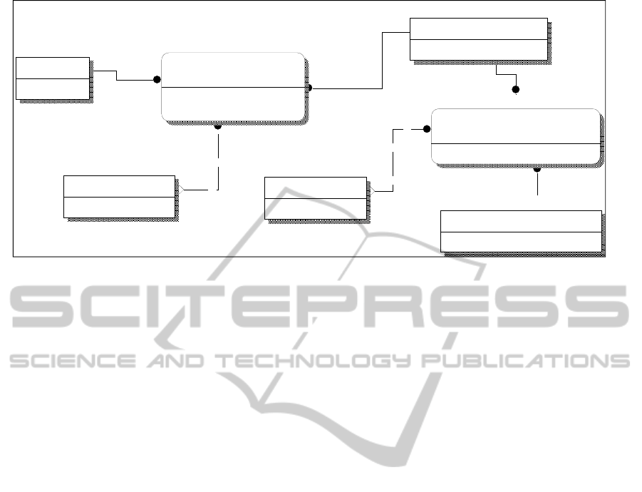
Figure 1: ER diagram from the main ER/Class cloud model introducing the FD concept.
∧ (1 ≤ i ≤ Max(Domain(x).[VLAN])) ∧
(Domain(x).[OS] = Network_Node(i).[OS]) }
Next we briefly look at a business system in the
context of existing compute models (e.g. client-
server) and then within a cloud environment. A
business system is loosely defined as a set of one or
more processes which, when combined, address the
requirements of a specific business problem. In the
traditional client-server model such systems were
implemented as one or more servers that were
dedicated to hosting the required business system
processes (Microsoft, 2001e). These were accessed
over one or more networks by individual sets of
workstations, whose functionality may have been
mutually exclusive with respect to each other.
Where the business process invoked requires
heterogeneous systems access, then there is a
problem with the current definition of the term
domain, referred to earlier, with respect to policy–
based control (0 et al., 2002, Stegmann, 1997), and
therefore the term functional policy domain or
functional domain should be used instead (Figure 1)
(Tezuka et al., 2000).
Throughout the paper the abbreviation Abs
stands for Abstraction / Abstracted, IPM for Inter-
Process Message and FK for Foreign Key.
This means that one dimension of the inheritance
of policy-based data may be controlled through the
specific business system being invoked by the client.
One of the key problems that is encountered in the
design and configuration of large-scale open
enterprise systems (Sutherland and Van den Heuvel,
2002, Murray, 2009, Nezlek et al., 1999, Pereira and
Sousa, 2004, Gorton and Liu, 2004, Arsanjani,
20020) is the lack of flexibility in the inherent
domain-mapping properties associated with the
operating systems of the network nodes (Figure 2).
This is combined with the properties relating to the
concept of ownership that are inherent within the
control structure of a domain; the domain is also in
turn normally tightly-coupled to either the operating
system or the network operating system of each
network node, such as Active Directory (Desmond
and Richardson, 2009) in the case of the Windows
operating system or X.500 (Chadwick, 1994) in the
case of Unix. This situation leads to an inherent
problem in that control structures formed through
the use of policies and profiles have to be repeated
for each operating system domain and between each
level of integration with the target network node or
network group. Where the design of a network
domain follows a strict, yet standard, hierarchy in
accordance with a relatively simple and repeatable
QMS (Quality Management System) requirement
model, there is a 1:M relationship between the
operating system/control system (e.g. Active
Directory) and the network node. There is also a
1:M relationship between the operating
system/control system and the associated business
systems. Both of these relationships do not lend any
significant degree of flexibility to their environment,
and as such are not specifically suited to fulfilling
the role of a control system within a cloud.
2.2 New Approach
To date the modelling which has been proposed for
the basic inter-communication management
structural methods, within the structure of a cloud,
uses the concept of abstraction classes (Eccles and
Loizou, 2010a, b) within the context of large-scale
Cloud
Cloud_ID
Cloud_Name
Cloud_FD_Mapping
Functional_Domain_ID (FK)
Cloud_ID (FK)
FD_Active_Status
FD_Def_ID (FK)
Functional_Domain
Functional_Domain_ID
Functional_Domain_Name
FD_Definition_Policy
FD_Def_ID
FD_Def_Name
Functional_Domain_Policy_Set
FD_Policy_ID
FD_Policy_Name
Operational_Policy
Op_Policy_ID
Op_Policy_Name
Func_Dom_Policy_Mapping_Env
Functional_Domain_ID (FK)
FD_Policy_ID (FK)
Op_Policy_ID (FK)
FUNCTIONAL DOMAIN CONCEPTS IN THE MODELLING OF CLOUD STRUCTURES AND THE BEHAVIOUR
OF INTEGRATED POLICY-BASED SYSTEMS THROUGH THE USE OF ABSTRACTION CLASSES
87
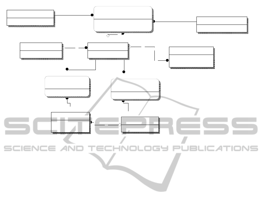
Figure 2: ER subschema showing the relationship between the FD concept and a conventional domain structure.
enterprise design structures. The next level of
structure that we propose is termed the Functional
Domain (Figure 1), and constitutes a logical area
within an Enterprise Domain (ED) that is defined by
the constraints of that domain or as a consequence of
the design policies that together define the properties
of that FD
The class of ED that is proposed to utilise a set
of related component structures, such as FDs, is that
of a cloud (Figure 1). The set of application
components linked to an enterprise function is called
the FD of that enterprise function (Wendt et al.,
2005). The elements of an FD require functional
integration with regard to the enterprise function
given. The given set of enterprise functions
correlates with the set of abstraction classes referred
to above. These may be integrated with respect to
their joint class of function by association with one
or more individual FDs (Figure 3, Figure 4). As
such, the resultant properties of the abstraction class
may vary as a consequence of belonging to a
specific FD, and the variation of these properties is
expressed via the policy or policies associated with
that specific FD. The FD may be enabled as part of
the design structure for the virtualised cloud
environment, and the methodology and design
structure for this are the subject of a future paper.
Such a policy may be modified by being part of an
operational policy class (Figure 3), which therefore
enables what is being invoked as opposed to how
such an invocation process is taking place.
A key operational requirement within an
environment, such as a cloud, is to be able to have a
control system that can take advantage of the
dynamic nature of such an operational scenario. One
of the key attributes of the concept of the FD,
referred to in this paper, involves the M:M
relationship to a business system (Figure 2). This
gives the required degree of flexibility necessary to
enable multiple business systems functions (e.g.
services) to relate to multiple degrees of control
structure on a peer-to-peer basis in conjunction with
hierarchies within a cloud. This naturally leads to the
following formalism for the logical representation of
the properties of a generic FD ; namely,
∀ Network_Node(x
i
) ∃ { Functional_Domain(y) |
Network_Node(x
i
) ∈ {Functional_Domain(y)}
∧ ((1 ≤ y
≤ Max(Functional_Domain(y)))
∧ (1 ≤ x
i
≤ Max(Network_Node(x
i
))))
∧ ((Network_Node(x
i
)
∈ {Business_System.Node(a
i
)})
∧ (1 ≤ a
i
≤ Max(Business_System.Node(a
i
))))
∧ ((Business_System.Node(a
i
)
∈ {Functional_Domain(y).BusSys(z)})
∧ (1 ≤ z ≤
Max(Functional_Domain(y).BusSys(z)))) }
The concept of the FD, as it is herein presented,
enables the requirement that a node may belong
either to different domains within an operational
session, depending on the set of abstracted processes
Network_Node
Network_Node_ID
Node_Class_ID (FK)
Network_Node_Class
Node_Class_ID
Node_Class_Name
IP_Address
IP_Address
IP_Subnet_ID (FK)
Network_Node_ID (FK)
OS_Domain_Nodes
Network_Node_ID (FK)
OS_Domain_ID (FK)
Non_OS_Domain_Nodes
OS_ID (FK)
Network_Node_ID (FK)
OS_Domain
OS_Domain_ID
OS_Domain_Name
OS_ID (FK)
Operating_System
OS_ID
OS_Name
Functional_Domain
Functional_Domain_ID
Functional_Domain_Name
Func_Dom_Node_Membership
Functional_Domain_ID (FK)
Business_System_ID (FK)
FD_Policy_ID (FK)
Network_Node_ID (FK)
Business_System
Business_System_ID
Busines_System_Name
CLOSER 2011 - International Conference on Cloud Computing and Services Science
88
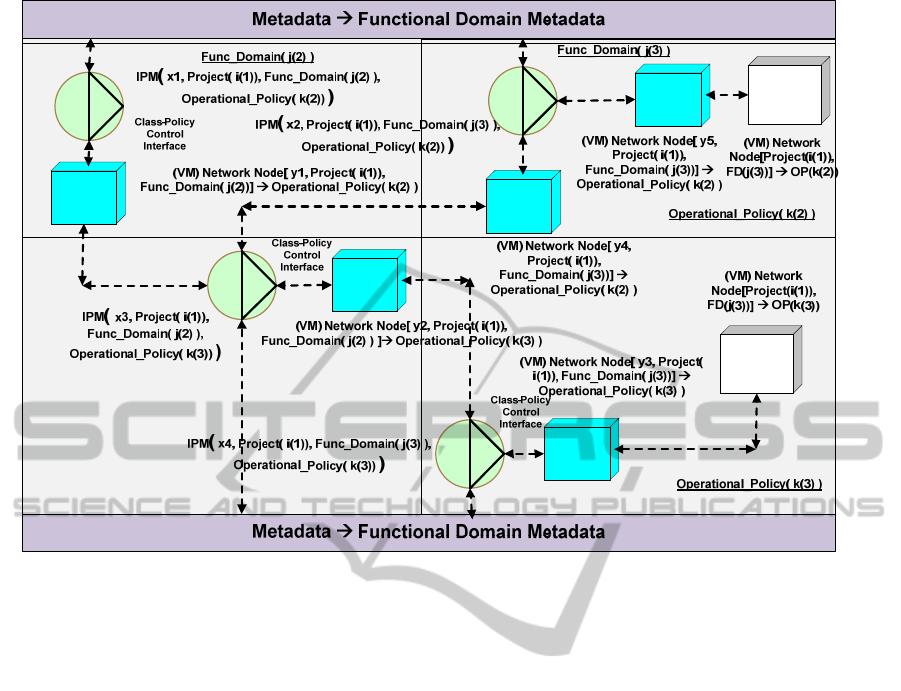
Figure 3: Abstraction Classes (VMs) in a cloud structure realised within the context of FDs and associated operational
policies. The metadata contains the definition of the operational policies, the location of the classes of operational functions
and the application of each such function within each host FD. These functions are accessed directly by the IPM modules,
using local policies specific to each IPM or IPM Class ID within an FD, Operational Policy (OP) area.
being invoked; or alternatively, it may be a member
of more than one domain simultaneously. By
abstracting the concept of the network node (Figure
5) within a cloud, each Network_Node object can be
associated with different subclasses of abstracted
cloud classes, such as those of users, user groups or
workstations (Figure 9)
3 DESIGN OF A GENERIC
APPROACH
There is a great degree of overlap in the structure
and the basic design of a cloud when compared to a
large-scale open enterprise system.
Many current definitions, and in some cases
working models of systems, described as clouds,
essentially comply with this basic characteristic
(Traore and Ye, 2003). The additional characteristics
of sets of services are presented as accessible utility
functions. However, it is also reasonable to assert
that a cloud differs from a large-scale open
enterprise system in that the internal structure may
vary in both its apparent architecture and in the
presentation over time on a dynamic basis.
Therefore, the points of reference used for internal
processing, and which may be available to external
events, may also vary in their nature and in their
location, leading to variations in the complexity of
cloud systems. Such variations may depend on the
interaction between other clouds and external events.
This is further complemented by the goal of making
all functional attributes of a cloud abstracted with
reference to the means by which they are accessed or
referred to.
En passant we note that the initial focus for the
concept of FDs originates from an analogous
concept that is used in the field of protein structure
research (Bajaj et al., 2011). In this area rather than
using the amino acid composition to represent a
protein sample, the FD composition is introduced to
incorporate the sequence order-related features
(Vlahovicek, 2001, Chou and Cai, 2004). Therefore,
a protein is now represented in terms of the FD
composition in a lower-order memory space,
incorporating not only some sequence order-related
features but also some function-related features
within the representation.
FUNCTIONAL DOMAIN CONCEPTS IN THE MODELLING OF CLOUD STRUCTURES AND THE BEHAVIOUR
OF INTEGRATED POLICY-BASED SYSTEMS THROUGH THE USE OF ABSTRACTION CLASSES
89
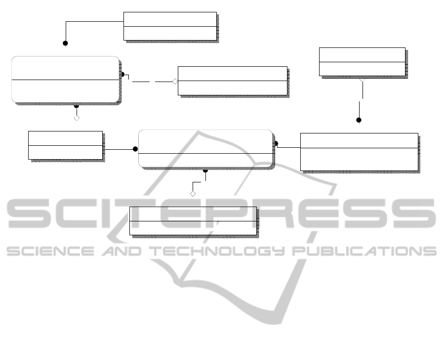
Figure 4: ER diagram for the control policy attributes within the cloud metadata that is responsible for governing the
operation of the FDs and the associated classes of NNs.
When a cloud is modelled by using a subset of
methods used for modelling other analogous
systems, the resultant artifact exhibits some
interesting properties.
One of the properties of the concept of an FD is
that of using it as an integral part of the generic
control structure, described later in this paper
(Figure 7, Figure 8), involving the use of policy
combined with event trapping in the context of one
or more sets of FDs, in order to produce an input
event command profile. Thus in order to achieve this
in a manner most applicable to each class of event, it
is required that the most appropriate class of control
policy be applied at the most relevant point within
the cloud. This is made possible through the use of
the layered metadata used to co-ordinate the control
management mechanisms within the cloud. The sets
of ER diagrams included in this paper are sub-
schemas taken from the overall metadata model of
the cloud and its associated management structures.
Some parts of the metadata database refer to the
nature and function of the said policies with
reference to their respective FDs (Figure 3), whilst
other parts form subschemas that relate to the
different aspects of the cloud and the control
structures (Figure 2) that are formulated for its
management through the use of integrated
frameworks (Traore and Ye, 2003). An example of
these are abstraction classes (Eccles and Loizou,
2010a, b). Within these ER diagrams can be seen
many instances of policy as they are applied to a
specific target entity (e.g. NN_AC_Policy_ID
applied to a specific Network_Node abstraction (see
Figure 4), where NN stands for Network_Node).
Thus, using the metadata ER design model (see
Figure 3), it becomes possible to finely tune the
policies with respect to both their content and their
direct applicability to the subject area to which they
are to be applied. (Policies are software-enabled
devices that enable a single instance of the
declaration of one or more rules concerning the state
of the environment in which they apply.)
It must be noted that the full model for the design of
the cloud, referred to in the discussion, incorporates
a much more complete range of techniques taken
from the Unified Modelling Language (UML)
(Bjorkander and Kobryn, 2003) and the Business
Process Modelling Notation (BPMN) (Caetano et al.,
2007). It must be observed that in order to
incorporate the output artifacts from these
techniques within a control metadata database that is
accessed by event-driven policies, for practical real-
time use, it is required to represent the artifacts
emanating from these techniques in a relational
manner using an ER model. The full methodology
for the proper design and construction of a cloud is
currently being developed, as we continue to
develop the management and control structures
through extending and modifying certain
architectures and standards for large-scale open
Functional_Domain
Functional_Domain_ID
Functional_Domain_Name
Func_Dom_Node_Membership
Functional_Domain_ID (FK)
Business_System_ID (FK)
FD_Policy_ID (FK)
Network_Node_ID (FK)
Network_Node
Network_Node_ID
Node_Class_ID (FK)
Network_Node_Abstraction_Class
Net_Node_Abs_Class_ID
User_Abs_Class_ID (FK)
Net_Node_Abs_Class_Name
Net_Node_Abstraction_Class_Policy
NN_AC_Policy_ID
NN_Abs_Policy_Name
Net_Node_Abstraction_Class_Mapping
Network_Node_ID (FK)
Net_Node_Abs_Class_ID (FK)
NN_AC_Policy_ID (FK)
Functional_Domain_Policy_Set
FD_Policy_ID
FD_Policy_Name
User_Abstraction_Class
User_Abs_Class_ID
User_Abs_Class_Name
CLOSER 2011 - International Conference on Cloud Computing and Services Science
90
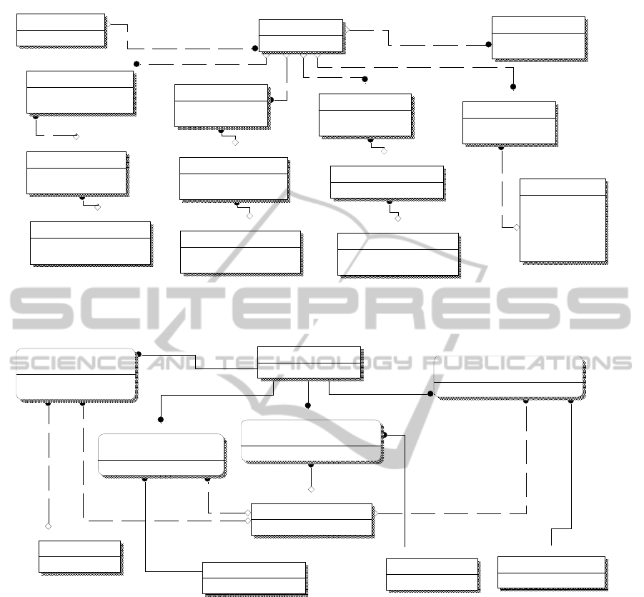
Figure 5: ER diagram representing the generic abstraction of different network entities related to the common entity
Network_Node.
Figure 6: ER diagram from the model of a cloud structure illustrating the abstracted nature of different classes of cloud-
based conceptual structures.
enterprise systems in order that they may be applied
to a cloud.
Control policies may be enabled with reference
to many different classes of Network_Node entity,
such as users, workstations and servers. In order for
the cloud model being developed to be correct with
respect to the characteristics described earlier, it
becomes essential to refer to the cloud components
in an abstracted sense, as shown in Figure 4 and
Figure 5, where NIC stands for Network Interface
Card, Con stands for Conceptual and Sw stands for
Switch. This concept is extended further in Figure 6
(SW stands for Software), where the functional
constructs hosted by the cloud, such as clusters,
applications, different classes of service objects are
also defined in an abstracted manner, each as part of
an FD.
In general, policies are used within specific FDs and,
for the most part, are applied to relatively simple
areas within those domains, such as user and
workstation configuration control. Within this
context, the general use of policies is either to
control the presentational level of processes, or to
control how their management may be restricted
with respect to their operating environment. Policies
may be applied using whatever form of rule-
interpretation is best suited to the local environment,
viewed in an abstracted manner. These policies may
in turn be associated with Active Directory objects,
such as sites, domains or OU’s (Desmond and
Network_Node
Network_Node_ID
Node_Class_ID (FK)
Network_Node_Class
Node_Class_ID
Node_Class_Name
A
bstracted_Server
A
bstracted_Server_ID
Con_Server_Name
Con_Serv_Class_ID (FK)
A
bstracted_Workstation
Workstation_ID
Workstation_Name
Con_Wkstn_Class_ID (FK)
Host_Server
Host_Server_ID
Host_Server_Name
Host_OS_ID (FK)
Cluster_ID (FK)
Host_Server_Version
Latest_Update
Blade_ID (FK)
IP_Address
IP_Address
IP_Subnet_ID (FK)
Network_Node_ID (FK)
Server_NIC
Server_NIC
A
bstracted_Server_ID (FK)
Network_Node_ID (FK)
Wkstn_NIC
Wkstn_NIC
Network_Node_ID (FK)
Workstation_ID (FK)
Host_NIC
Host_NIC
Host_Server_ID (FK)
Network_Node_ID (FK)
A
bstracted_Server_Class
Con_Serv_Class_ID
Con_Serv_Class_Name
Net_Node_Abs_Class_ID (FK)
A
bstracted_Wkstn_Class
Con_Wkstn_Class_ID
Con_Wk stn_Class_Name
Net_Node_Abs_Class_ID (FK)
Network_Switch_NIC
Net_Switch_NIC
Network_Node_ID (FK)
Net_Switch_ID (FK)
A
bstracted_Network_Switch
Net_Switch_ID
Con_Sw_Class_ID (FK)
A
bstracted_Net_Switch_Class
Con_Sw_Class_ID
Con_Sw_Class_Name
Net_Node_Abs_Class_ID (FK)
Functional_Domain
Functional_Domain_ID
Functional_Domain_Name
Network_Node
Network_Node_ID
Node_Class_ID (FK)
Func_Dom_Node_Membership
Functional_Domain_ID (FK)
Business_System_ID (FK)
FD_Policy_ID (FK)
Network_Node_ID (FK)
A
bstracted_Cluster
A
bstracted_Cluster_ID
A
bstracted_Cluster_Name
Func_Dom_Cluster_Membership
Functional_Domain_ID (FK)
A
bstracted_Cluster_ID (FK)
FD_Policy_ID (FK)
Functional_Domain_Policy_Set
FD_Policy_ID
FD_Policy_Name
A
bstracted_SW_Object
A
bstracted_SW _Obj_ID
A
bstracted_SW _Obj_Name
A
bstracted_Application
A
bstracted_App_ID
A
bstracted_App_Name
Func_Dom_Application_Membership
Functional_Domain_ID (FK)
A
bstracted_App_ID (FK)
FD_Policy_ID (FK)
Func_Dom_Abs_SW_Obj_Membership
Functional_Domain_ID (FK)
A
bstracted_SW_Obj_ID (FK)
FD_Policy_ID (FK)
FUNCTIONAL DOMAIN CONCEPTS IN THE MODELLING OF CLOUD STRUCTURES AND THE BEHAVIOUR
OF INTEGRATED POLICY-BASED SYSTEMS THROUGH THE USE OF ABSTRACTION CLASSES
91
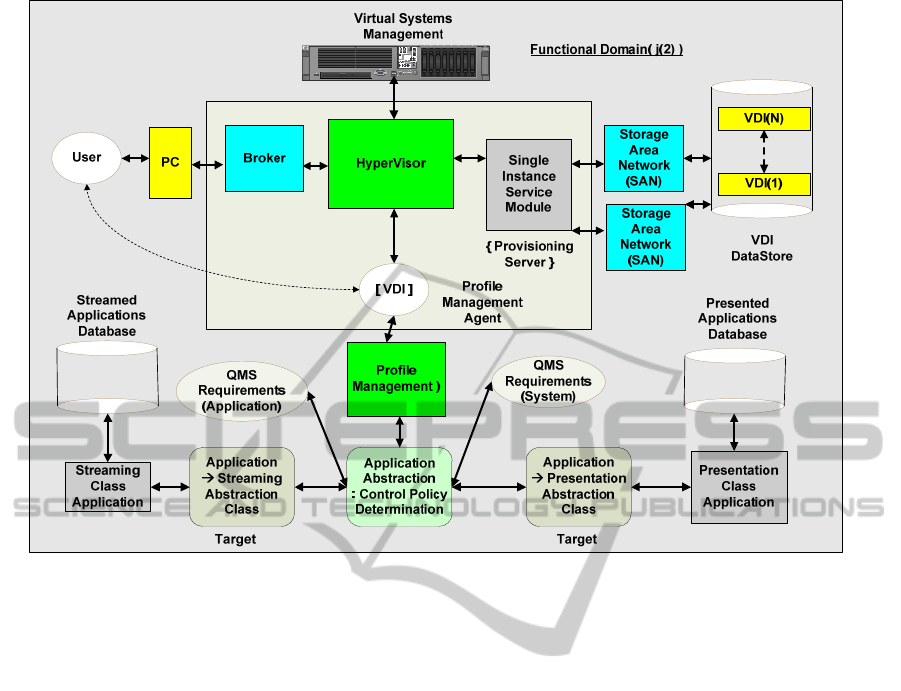
Figure 7: An intra-cloud dataflow structure employing an input (user) event, a control policy from the relevant FD, and a
resultant control profile in the selection of an abstracted (user) application.
Richardson, 2009, Allen and Lowe-Norris, 2003,
Allen, 2003). System policies enable local registry
values to be overridden with settings specific to the
particular process being addressed. Control policies
are defined in a policy file, normally located in an
area that is accessible to the requesting process.
The policies enabled through the use of FDs are
closer to the class of Control Policies than, for
example, the class of firewall policies (Lee et al.,
2003, Lee et al., 2002). As such, these are more in
keeping with the class of policy that may be utilised
in control structures such as those encountered in the
SOA context model (Zhou and Liu, 2010).(In Figure
7 VDI stands for Virtual Desktop Interface).
An example of such a class of process is the
Application Abstraction: Control Policy
Determination that is shown in Figure 7. As a result
of such a process, a resultant policy is formulated
from the system policy settings and the user policy
and/or default settings in the local registry
(Microsoft, 2001a), depending on the relative
security settings of each class of policy owner.
Based on the appropriate control structure, the
instance of this latter resultant process produced
from the Control Policy Determination process
results in the formulation of the system profile,
which controls the target process to be accessed
(Figure 7). Figure 7 represents an example of a
standard method of invoking abstraction classes
within a cloud structure using events that are
formulated such that the event class, the policy
acquisition, the profile generation and the associated
functional access are all derived at the abstract level.
Initially on receipt of the initial input event class (e.g.
a logon process), the local configuration information
is checked for the location of the policy file
(Microsoft, 2001b). The policies are then
downloaded by initially checking as to whether the
event profiles are enabled. If so, the policy file is
searched for the relevant event and, if found, then
the event-specific policy is enabled. If not then the
default user policy is enabled (Posey, 2001). If
group policy support (Microsoft, 2001c, d) has been
enabled, then it is established as to whether the user
is a member of any of the relevant set of groups. If
so, then the group information is downloaded
beginning with the lowest-priority group and ending
with the highest, thereby enabling the data belonging
to the latter group to supersede the rest. This is then
copied to the registry of the abstracted host, or its
equivalent. The policy file is then checked for
information pertaining to the relevant abstracted host.
If this exists, then the relevant policies are applied to
the environment of the abstracted host.
CLOSER 2011 - International Conference on Cloud Computing and Services Science
92
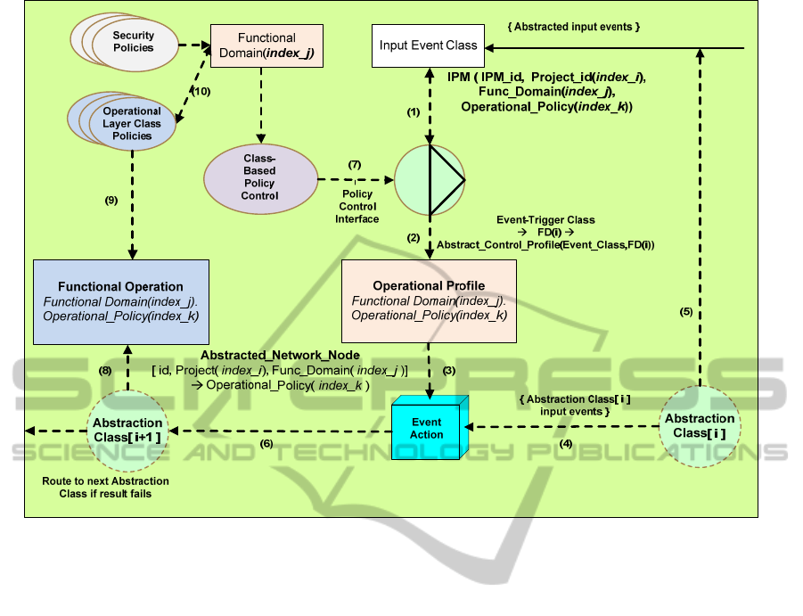
Figure 8: A low-level view of the interaction between the FD (Functional_Domain(index_j)), Policy
(Operational_Policy(index_k)) and Events to produce the control structure by way of an Operational Policy for the
Functional Operation.(Cf. Application Abstraction:Control Policy Determination in Figure 7).
Network-based policies within a cloud,
controlling the interpretation of event class
information and the actions that are undertaken as a
consequence of such events being invoked, are
examples of threshold management applications. An
example of this is Threshold Manager (Cisco, 1997),
which allows thresholds to be set and retrieves event
information. Thresholds can be set for targeted
abstracted nodes using threshold policies,
implemented as sets of configuration data that
specify the conditions for triggering a threshold
event for a particular management attribute affected
across a particular node given certain constraints
(Microsoft, 1997, Microsoft, 2001c, e).
An event is essentially a change of state of a
system, where the quantifying of the degree of
change of the system depends on both the class of
the event and the environment within which it
occurs. That is to say, both the nature of the event
and the method of its measurement will depend on
the class model of the relevant event and the class of
FD within which it occurs. All captured events are
related to the values of threshold-related events and
then cross-referenced to the user-configured
threshold policies.
In
Figure 8 we have determined to clarify the
explanation of the represented dataflows by labelling
each of the said dataflows from 1 to 10. These are
referred to in the ensuing text as, for example, (1),
(2), etc.
As shown in Figure 8, an abstracted input event
from a source other than an abstraction class is
examined by the policy control interface (1). This
uses the class-based control policy in conjunction
with the determined class of event to generate the
appropriate trigger for the operational profile
generation (2). This operational profile is to become
part of the protocol of the generated event (3), so as
to enable correct operation within the context of the
FD of the next abstraction class (6). This event
action may also be directly input through the use of
an abstraction class (4) or indirectly input through
the latter set of processes, if there is a requirement
for an operational profile to be generated (5). The
control policy sets the thresholds (7) that are set for
the class of input events (e.g. Systems Network
Management Protocol (SNMP) events), generated
from the local Management Information Base (MIB)
database variables, which exist in the local
environment controlled by the specified FD.
FUNCTIONAL DOMAIN CONCEPTS IN THE MODELLING OF CLOUD STRUCTURES AND THE BEHAVIOUR
OF INTEGRATED POLICY-BASED SYSTEMS THROUGH THE USE OF ABSTRACTION CLASSES
93
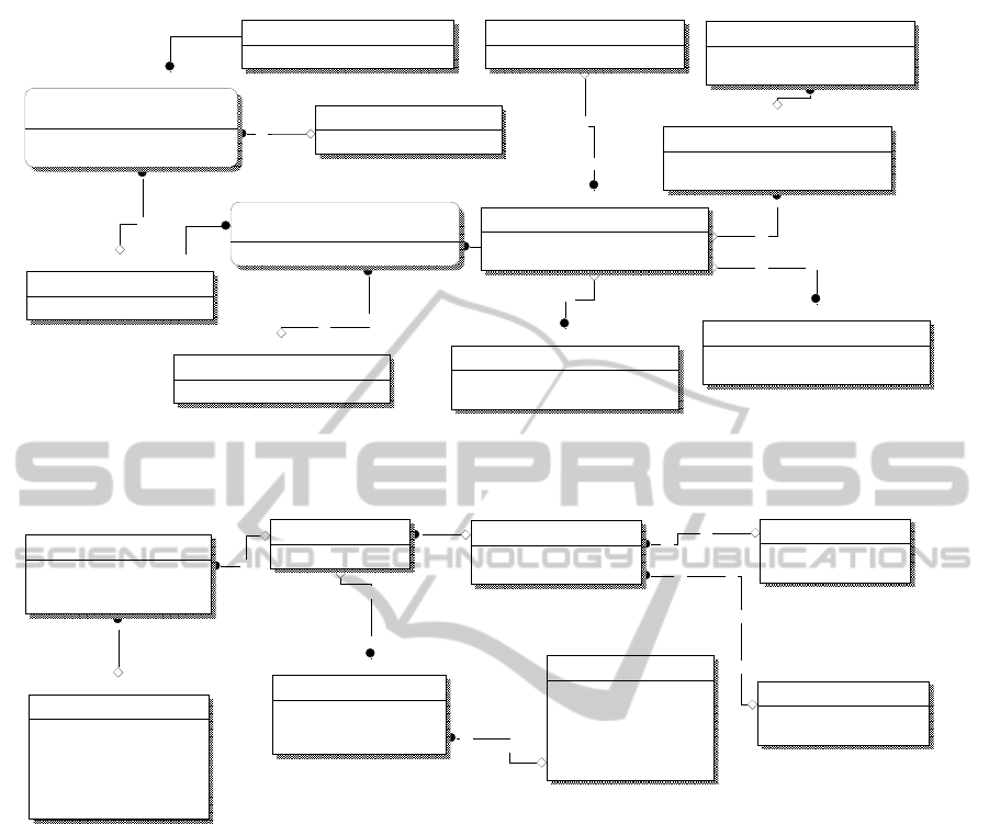
Figure 9: ER subschema to show how the abstraction of the Network_Node entity is conceptually related to the abstracted
layer of equivalent network entities with a 1:1 relationship.
Figure 10: ER subschema of a cloud model showing the entity Abstracted_Server and how this is related to physical /virtual
servers irrespective of their operational state within a dynamic cloud environment.
The profile is generated as a consequence of the
specific FD (2) adapting the local control policies in
accordance with its own internal policy, producing a
localised profile control structure for the input event
classes. The generated event calls the next
abstraction class in the relevant sequence of
abstraction classes derived from the controlling
metadata (Figure 3). In Figure 8 this next abstraction
class locates an instance of an object that will
perform the functional operation required (8), which
is itself influenced by the operational layer class
policies (9) in conjunction with the current FD (10).
This leads to the production of a set of abstracted
levels of technical (business) systems within a cloud
model; these systems lead to the simplification of
the management of the sets of their points of control.
An initial example of this is given in Figure 10,
where the entity Abstracted_Server is the point of
control that relates to the Server technical business
system. This is then related to the entity
Functional_Domain by way of the entity
Network_Node in Figure 9. It is thus demonstrated
how the dynamic properties of a cloud, referred to
earlier in this section, may be expressed by means of
the entity Operational_Server_Instance via the use
of the attribute Operation_State. This enables simple
centralised control at an abstracted level of the
different classes of server, where the current
practical requirements of implementing that specific
server, or set of servers, change depending on
whether the servers in question be physical or virtual.
As a result of the salient concept of FDs, there is
an associated class of control policy (Functional_
Domain_Policy_Set) that relates each FD and the
abstraction class of each Network_Node, as shown
in Figure 9. Each such policy interacts with the
Functional_Domain
Functional_Domain_ID: Long Intege
r
Functional_Domain_Name: Text(20)
Func_Dom_Node_Membership
Functional_Domain_ID: Long Intege
r
Business_System_ID: Long Integer
FD_Policy_ID: Long Integer
Network_Node_ID: Long Integer
Network_Node
Network_Node_ID: Long Intege
r
Node_Class_ID: Long Integer
Functional_Domain_Policy_Set
FD_Policy_ID: Long Integer
FD_Policy_Name: Text(20)
Net_Node_Abstraction_Class_Mapping
Network_Node_ID: Long Integer
Net_Node_Abs_Class_ID: Long Integer
NN_AC_Policy_ID: Long Integer
Net_Node_Abstraction_Class_Policy
NN_AC_Policy_ID: Long Integer
NN_Abs_Policy_Name: Text(20)
User_Abstraction_Class
User_Abs_Class_ID: Long Intege
r
User_Abs_Class_Name: Text(20)
Network_Node_Abstraction_Class
Net_Node_Abs_Class_ID: Long Intege
r
User_Abs_Class_ID: Long Integer
Net_Node_Abs_Class_Name: Text(20)
A
bstracted_Server
A
bstracted_Server_ID: Long Intege
r
Con_Server_Name: Text(20)
Con_Serv_Class_ID: Long Integer
A
bstracted_Wkstn_Class
Con_Wkstn_Class_ID: Long Integer
Con_Wkstn_Class_Name: Text(20)
Net_Node_Abs_Class_ID: Long Intege
r
A
bstracted_Server_Class
Con_Serv_Class_ID: Long Integer
Con_Serv_Class_Name: Text(20)
Net_Node_Abs_Class_ID: Long Intege
r
A
bstracted_Net_Switch_Class
Con_Sw_Class_ID: Long Integer
Con_Sw_Class_Name: Text(20)
Net_Node_Abs_Class_ID: Long Intege
r
A
bstracted_Server
Conceptual_Server_ID
Con_Server_Name
Con_Serv_Class_ID (FK)
Operational_Server_Instance
Op_Server_ID
Conceptual_Server_ID (FK)
Operation_State_ID (FK)
Physical_Server
Physical_Server_ID
Physical_Server_Name
Cloud_Server_ID (FK)
Physical_Server_Class_ID (FK)
Virtual_Machine
Virtual_Machine_ID
Virtual_Machine_Name
Virtual_Server_Class_ID (FK)
Cloud_Server_ID (FK)
Physical_Server_Class
Physical_Server_Class_ID
Physical_Server_Class_Name
Number_of_CPUs
CPU_Frequency
RAM
C_drive
D_drive
Virtual_Server_Class
Virtual_Server_Class_ID
Virtual_Server_Class_Name
vCP U
vCP U_F re q
vRA M
vC_ dr ive
vD_ dr ive
Cloud_Server_Mapping
Cloud_Server_ID
Op_Server_ID (FK)
Operation_State_Class
Operation_State_ID
Operation_State_Description
Operation_State_Name
CLOSER 2011 - International Conference on Cloud Computing and Services Science
94
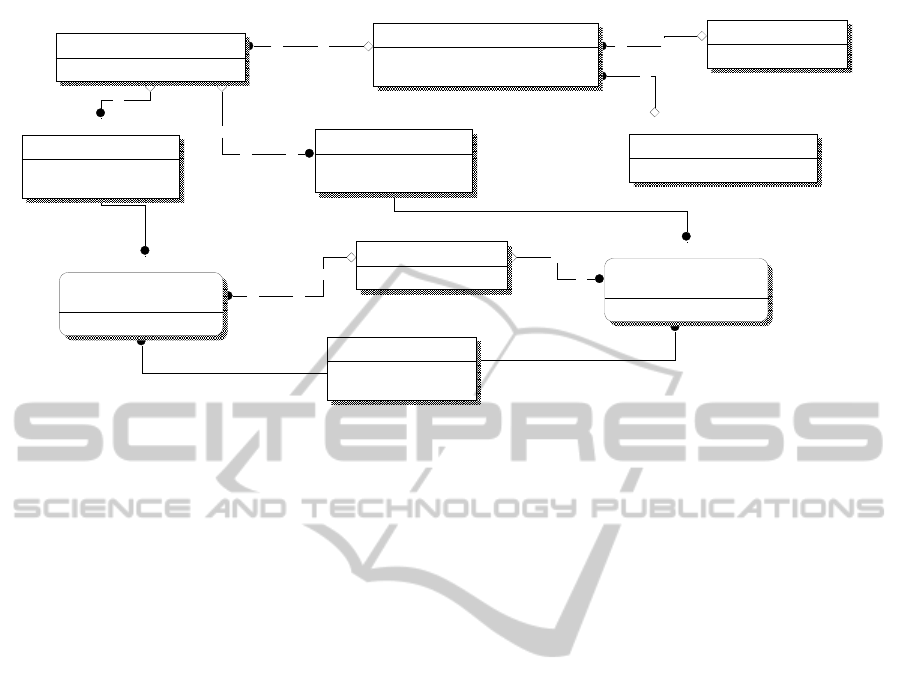
Figure 11: ER subschema from a cloud model to show how the abstraction of an application can be used to control the
nature of the implementation interface depending on the entity Selection_Control_Policy and the process Application
Abstraction : Control Policy Determination in Figure 7.
policy for the abstracted Network_Node as shown in
Figure 9 (Net_Node_Abstraction_ Class_Policy).
The latter policy will inherit from the former in
order to produce a resultant policy for the specific
abstracted Network_Node class with respect to the
FD in which it is located (De Bruijn and De Vreede,
1999). This process is more complex than it
seemingly is, due to the possible M:M relationship
between the entities Functional_ Domain and
Network_Node, implemented as the control entity
Func_Dom_Node_Membership in Figure 9.
As shown in Figure 12, this design is put into
practical use by means of a generic architecture that
produces a system able to operate within a cloud
environment as well as a large-scale virtual/physical
environment. This system is designed to utilise
virtualised applications rather than install them on a
target network node, typically a workstation.
Utilising this mechanism within an FD- controlled
cloud environment may result in the location of the
virtualised applications shifting with FD policy–
based rules, due to the dynamic nature of the cloud.
It is also the case that as the access mechanism for
the virtualised applications is abstracted, there is no
need to change the initial function call made to the
application via the Initiator Process Node in Figure
12, nor to the target node (e.g. workstation/server),
since both are abstracted (Figure 5). This gives the
initial basis for a very flexible management system
that is intended to serve as the basis for a control
system employed for a cloud construct currently
under development. A prototype of this design
construct is now under development / testing.
4 DISCUSSION
Once a virtualised environment has been properly
developed as a computing resource for a specific
business, or set of businesses, a new set of problems
emerge which are only now being recognised and
addressed. To begin with, the methodology and
associated modelling structure must now become an
intricate part of the active operational structure as
well as the more passive system management, since
the idea of the total replacement of layers of the
system will no longer be applicable. Therefore, the
complete set of artifacts used to model and design
the full range of components contributing to a cloud
control and management system must be
implemented as a data model. In practice this
becomes a distributed system and is the subject of
impending future research.
Finally, there is a need for subsequent research
concerning the integration of the concept of
functional policy domains with different network-
based operating systems. This must be extended to
deal with policy integration between different
domains (FDs) and between different types of such
domains in the context of a network environment.
This is being addressed by designing policies and
network-based systems in an abstracted manner.
A
bstracted_Application
A
bstracted_App_ID
A
bstracted_App_Name
Operational_Application
Operational_Application_ID
A
bstracted_Application_ID (FK)
A
pplication_Operational_State_ID (FK)
Streaming_Application
Streamed_App_ID
Streamed_App_Name
Cloud_Application_ID (FK)
A
bstracted_Server
A
bstracted_Server_ID
Con_Server_Name
Con_Serv_Class_ID (FK)
Streaming_Interface
Streamed_App_ID (FK)
A
bstracted_Server_ID (FK)
A
pp_Select_Policy_ID (FK)
Selection_Control_Policy
A
pp_Select_Policy_ID
Presentation_Application
Presentation_App_ID
Presentation_App_Name
Cloud_Application_ID (FK)
Presentation_Interface
Presentation_App_ID (FK)
A
bstracted_Server_ID (FK)
A
pp_Select_Policy_ID (FK)
A
pplication_Operational_State
A
pplication_Operation_State_ID
A
pplication_Operational_State
Cloud_Application_Mapping
Cloud_Application_ID
Operational_Application_ID (FK)
FUNCTIONAL DOMAIN CONCEPTS IN THE MODELLING OF CLOUD STRUCTURES AND THE BEHAVIOUR
OF INTEGRATED POLICY-BASED SYSTEMS THROUGH THE USE OF ABSTRACTION CLASSES
95
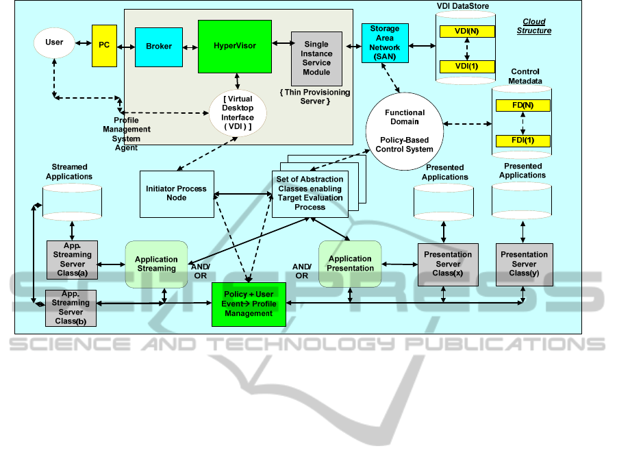
Figure 12: Summary diagram showing a generic control-flow system for the activation of an application by either
Presentation or Streaming mechanisms within the context of one or more FDs.
5 CONCLUSIONS
We have shown how formulating a set of simple
extensions to the object control policy methodology
by using the concept of FDs can produce the basis
for a policy-based network, which governs not only
how an object is initiated, but introduces seamless
flexibility into specifying which class of the
functional application should be invoked. This can
be tested using a cloud model, which is being
produced from an evolving cloud development
methodology; this is the subject of an upcoming
paper.
REFERENCES
Allen, R., 2003. Active Directory Cookbook, O’Reilly.
London.
Allen, R., Lowe-Norris, A.G., 2003. Active Directory,
O’Reilly. London, 2
nd
edition.
Arsanjani, A., 2002. Developing and Integrating
Enterprise Components and Services. Communications
of the ACM, 45, 10, pp.31-34.
Bajaj, C., Chowdhury, R.A., Rasheed, M., 2011. A
Dynamic Data Structure for Flexible Molecular
Maintenance and Informatics. BioInformatics, 27, 1,
pp.55-62.
Bjorkander, M., Kobryn, C., 2003. Architecting Systems
with UML 2.0. IEEE Software, 20, 4, pp.57-61.
Caetano, A., Pombinho, J., Tribolet, J., 2007.
Representing Organizational Competencies. In ACM
SAC’07, pp.1257-1262. ACM Press.
Chadwick, D., 1994. Understanding X.500, Chapman &
Hall. London.
Chou, K., Cai, Y., 2004. Predicting Protein Structural
Class by Functional Domain Composition.
Biochemical and Biophysical Research
Communications, 321, pp.1007–1009.
Cisco Systems Inc., 1997. Using Threshold Manager.
Cisco White Paper. Cisco Press.
Damianou, N., Bandara, A.K., Sloman, M., Lupu, E.C.,
2002. A Survey of Policy Specification Approaches.
Submission for Review. < http://www.doc.ic.ac.uk/
~mss/Papers/PolicySurvey.pdf > .
De Bruijn, H., de Vreede, G., 1999. Exploring the
Boundaries of Successful GSS Applications. In
Proceedings of the 33
rd
IEEE Hawaii International
Conference on Systems Science. IEEE Press.
Desmond, D., Richardson, J., 2009. Active Directory ;
Design, Deploying and Running Active Directory,
O’Reilly. London.
Eccles, J., Loizou, G., 2010a. An Approach to Enable
Cloud Computing by the Abstraction of Event-
Processing Classes. GSTF International Journal on
Computing, 1, 1, pp.138-144.
Eccles, J., Loizou., G. 2010b. A Cloud-Computing
Environment Based on a Model of Integrated
Abstraction Classes. In Annual International
CLOSER 2011 - International Conference on Cloud Computing and Services Science
96

Conference on Cloud Computing and Virtualization,
CCV 2010, pp.153-162.
Gorton, I., Liu, A., 2004. Architectures and Technologies
for Enterprise Application Integration. In IEEE
Proceedings of the 26th International Conference on
Software Engineering (ICSE’04). IEEE Press.
Lee, T.K., Yusuf, S., Luk, W., Sloman, M., Lupu, E.,
Dulay, N., 2003. Compiling Policy Descriptions into
Reconfigurable Firewall Processors. In Proceedings of
the 11th Annual IEEE Symposium on Field-
Programmable Custom Computing Machines
(FCCM’03). IEEE Press.
Lee, T.K., Yusuf, S., Luk, W., Sloman, M., Lupu, E.,
Dulay, N., 2002. Development Framework for
Firewall Processors. In Proceedings of the IEEE
International Conference on Field-Programmable
Technology. IEEE Press.
Microsoft Corporation, 1997. Guide to Microsoft Windows
NT 4.0: Profiles and Policies. Microsoft Windows NT
Server White Paper. Microsoft.
Microsoft Corporation, May 2001a. System Policies.
Technical Information, Chapter 8. Microsoft.
Microsoft Corporation, May 2001b. User Profiles and
System Policies. Technical Information, Chapter 15.
Microsoft.
Microsoft Corporation, May 2001c. Step-by-Step Guide to
Understanding the Group Policy Feature Set.
Operating System White Paper. Technical Information.
Microsoft.
Microsoft Corporation, May 2001d. Introduction to
Windows2000 Group Policy. Operating System White
Paper. Technical Information. Microsoft.
Microsoft Corporation, May 2001e. Windows DNA
Architecture Design: A Scalable, Highly Available
Business Object Architecture. White Paper. Technical
Information. Microsoft.
Murray, P., 2009. Enterprise Grade Cloud Computing. In
WDDDM’09. ACM Press.
Nezlek, G.S., Jain, H.K., Nazareth, D.L., 1999. An
Integrated Approach to Enterprise Computing
Architectures. Communications of the ACM, 42, 11,
pp.82-90.
Nielsen, M.S., 1999. Windows 2000 Server Architecture
and Planning, Coriolis Group Publishers. Scottsdale,
Arizona.
Pereira, C.M., Sousa, P., 2004. A Method to Define
Enterprise Architectures using the Zachman
Framework. In ACM Symposium on Applied
Computing (SAC’004). ACM Press.
Posey, B.M., May 2001. Protecting Users from
Themselves. Technical Information, Microsoft
Corporation. Microsoft.
Stegmann, C., 1997. A Framework for Authorization
Policies,
Professional Thesis. Institut Eurécom, IBM
Zurich Research Laboratory, Rüschlikon, Switzerland.
Sutherland, J., Jan van den Heuvel, W., 2002. Enterprise
Application Integration and Complex Adaptive
Systems. Communications of the ACM, 45, 10, pp.59-
64.
Tezuka, S., Sasaki, R., Kataoka, M.(Hitachi Ltd), 2000.
Seamless Object Authentication in Different Security
Policy Domains. In Proc. 33
rd
Hawaii IEEE
International Conference on Systems Science. IEEE
Press.
Traore, D.B., Ye, H., 2003. An Integrated Framework for
Forma1 Deve1opment of Open Distributed Systems.
In ACM Symposium on Applied Computing (SAC2003).
ACM Press.
Vlahovicek, M.J., 13
th
April 2001. Prediction of Protein
Functional Domains from Sequences using Artificial
Neural Networks. In Genome Research. Cold Spring
Harbor Laboratory Press. < http://www.genome.org/
cgi/doi/10.1101/gr.168701 >.
Wendt, T., Brigi, B., Winter, A., Nov 4
th
2005. Assessing
the Integration of Information System Components. In
ACM IHIS’05. ACM Press.
Yu Chen Zhou, Y., Xin Peng Liu, 2010. Context Model
SOA Policy Framework. In IEEE International
Conference on Web Services. IEEE Press.
FUNCTIONAL DOMAIN CONCEPTS IN THE MODELLING OF CLOUD STRUCTURES AND THE BEHAVIOUR
OF INTEGRATED POLICY-BASED SYSTEMS THROUGH THE USE OF ABSTRACTION CLASSES
97
