
VELOCITY AND ORIENTATION CONTROL IN AN ELECTRICAL
WHEELCHAIR ON AN INCLINED AND SLIPPERY SURFACE
S. O. Onyango
1
, Y. Hamam
2
and K. Djouani
3
1
F’SATI–Tshwane University of Technology, Pretoria, South Africa
2
ESIEE-Paris, Paris Est University, Noisy-le-Grand, France
F’SATI - Tshwane University of Technology, Pretoria, South Africa
LISV laboratory, UVSQ Velizy, Versailles, France
3
LISSI Laboratory, Paris Est University, Val de Marn´e, France
F’SATI - Tshwane University of Technology, Pretoria, South Africa
Keywords:
Modelling, Gravity, Input–output linearization, Slip, Control, Wheelchair.
Abstract:
People with disability increase everyday due to accidents, poor health care and aging of the population. While
some of these disabled people are strong enough and can comfortably use manual wheelchairs to move, others
are too weak and may find it extremely difficult to drive powered wheelchairs with basic functionalities.
Wheelchairs adaptable to various specialized functionalities may therefore be important if mobility of the
severely disabled persons isto be ensured. Control parameters adaptable to hand, tongue or even head joysticks
may consequently be necessary. Authors of this paper considered linear velocity and angular position for
control. With such control parameters the wheelchair user may navigate and reach every desired location. To
mimic real outdoor situations, slippery, inclined and flat surfaces are also considered. The dynamic modelling
procedure used in this paper is based on the Euler–Lagrange formalism. The wheelchair platform considered
in this paper is a differential drive platform with two passive front caster wheels and two active rear wheels.
1 INTRODUCTION
Thousands of people with disability worldwide take
advantage of wheelchair for their daily (Vignier
et al., 2008; Woude et al., 2006; Wobbrock et al.,
2004). A number of these disabled persons drive
their wheelchairs out-of-doors. In such environments,
they encounter extremely bumpy and slippery road
surfaces making it very difficult for the wheelchair
to navigate. Such adverse road conditions may con-
sequence into dangerous slipping of the wheelchair
platform and result into severe accidents to the al-
ready disabled wheelchair user. Dynamic modelling
process should as a result consider adverse ground
characteristics and the topographies of the road upon
which the wheelchair will be moving. The majority
researchers base their work on the kinematic mod-
els of wheelchair platforms in modelling,(Tarokh and
McDermott, 2005; Zhu et al., 2006). Such models
however fail to account for the acceleration and can
significantly differ from the actual movement when-
ever the handling limits of the wheelchair are ap-
proached. Dynamic modelling as a result becomes
the only option if accurate analysis of wheelchair is
to be ensured. Most of the researchers have con-
sidered dynamic modelling in their research (Dixon
et al., 2001; Kozlowski and Pazderski, 2004; Motte
and Guy, 2000; Stonier et al., 2007; Williams et al.,
2002), however such work restrict the platforms to
flat surfaces alone and for that reason do not ac-
count for the variations on gravitational forces affect-
ing wheelchair during its motion on inclined surfaces.
Other researchers have also taken into account fric-
tional forces in dynamic modelling (Williams et al.,
2002; Sidek, 2008; Kozlowski and Pazderski, 2004;
Hamed et al., 2007). In this work a dynamic model
of wheelchair platform is considered. This model ac-
counts for gravitational forces, frictional forces and
slipping effects.
Control of nonlinear systems is among the very
challenging fields of research. This is because
there lacks a generic method for controller synthe-
sis (Isidori, 1995; Khalil, 1996). Few of the pos-
sible methods consist of feedback linearization and
Lyapunov functions (Isidori, 1995). For the latter,
there is no systematic way of construction of the func-
112
O. Onyango S., Hamam Y. and Djouani K..
VELOCITY AND ORIENTATION CONTROL IN AN ELECTRICAL WHEELCHAIR ON AN INCLINED AND SLIPPERY SURFACE.
DOI: 10.5220/0003416301120119
In Proceedings of the 8th International Conference on Informatics in Control, Automation and Robotics (ICINCO-2011), pages 112-119
ISBN: 978-989-8425-75-1
Copyright
c
2011 SCITEPRESS (Science and Technology Publications, Lda.)
tion except for passive systems (Spong et al., 1989),
the former is the other method considered in this pa-
per. Input–output feedback linearization linearizes
only part of the dynamics between the output and in-
put. Feedback linearization has been used earlier in
(Ortega et al., 2000). With this method, nonlinearities
are pushed to the internal dynamics in order that the
behavior of input–output is minimum phase. Nonlin-
ear state transformation and nonlinear state feedback
is then used to recompense system nonlinearities. A
linear controller is then designed and employed to
control the linearized system (Ortega et al., 2000).
This paper is organized as follows. In section II the
dynamic model of an electric powered wheelchair
which includes dynamics of friction and gravity
forces of uphill and downhill movementsis presented.
Input–output feedback linearization is utilized in sec-
tion III to control linear velocity and angular position.
Finally in section IV, detailed simulation results are
presented to lay bare the importance of the proposed
modelling and control techniques. Some concluding
remarks are also presented.
2 DYNAMIC MODEL OF THE
WHEELCHAIR
2.1 A Nonholonomic Wheelchair
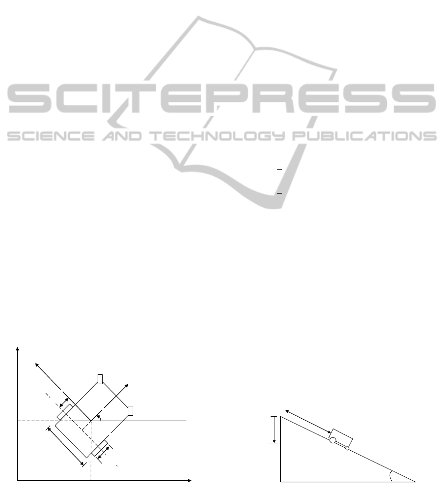
In this work, we consider the structure of wheelchair
platform shown in fig.1 for modeling and control. Fig.
1 consists of two independently drivenmotorizedhind
and two passive front castor wheels. Based on the dif-
ferential driveprinciple, authorsof this paper consider
angular velocity of the wheelchair platform above as
a function of the difference between angular veloci-
ties of right and left wheels. It is possible to achieve
a straight line trajectory whenever equal torques are
!
"
2#
−%
&
O
C
'
(
)
*
2+
'
*
Figure 1: Platform of the differential drive wheelchair.
applied to each of the rear wheels with identical mo-
tors. The wheelchair platform herein is considered
as a rigid body in derivation of the kinetic energy. La-
grange formalism is then used to derivethe general set
of differential equations that describes the time evolu-
tion of wheelchair subject to nonintergrablekinematic
constraints (Hamed et al., 2007; Wells, 1967).
In fig.1, components of the coordinate vector are
shown. The inertial coordinate frame is indicated
as (x,y,z) while the body fixed coordinate of the
wheelchair is indicated as (X,Y,Z) with c being the
origin. The position of the wheelchair in the inertial
frame is specified completely by; q = [x
g
,y
g
,z
g
,θ]
T
,
where, x
g
, y
g
and z
g
are the coordinates of the of the
wheelchair platform’s centre of gravity, the orienta-
tion of the wheelchair is described by θ while the road
inclination angle is indicated as φ according to fig.2.
2b is the length of the axis between the wheels of the
wheelchair platform and r is the radius of the wheels.
γ
R
and γ
L
are the angular rotations of the right wheel
and the left wheel respectively. The Lagrange func-
tion L which is difference between kinetic and po-
tential energies of the wheelchair may be expressed
as (Hamed et al., 2007; Wells, 1967);
L =
1
2
M(˙x
2
g
+ ˙y
2
g
+ ˙z
2
g
) +
1
2
I
z
˙
θ
2
+ Ml
˙
θcosφ( ˙x
g
sinθ − ˙y
g
cosθ)
−Mgsinφ(x
g
cosθ+ y
g
sinθ) (1)
where;
M = M
w
+ M
p
M
p
is the patients mass, M
w
is the total mass of
wheelchair plus its components, I
z
is the moment of
inertia of the wheelchair platform about z
g
, g is the
gravitational acceleration. With n as the dimensional
configuration space and q = (q
1
,... , q
n
) as the gen-
eralized coordinates subjected to (n− m) constraints,
the general expression of a nonholonomic wheelchair
may be illustrated by (Wells, 1967; Fierro and Lewis,
1997);
M(q) ¨q+C(q ˙q) ˙q+ F + G(q) = E (q)τ+ A
T
(q)λ
(2)
where;
M(q) ∈ R
n×n
is the symmetric positive definite in-
ertia matrix, G(q) ∈ R
n
is a vector of gravitational
sin ∅
∅
Figure 2: The wheelchair on an incline (D is the displace-
ment on xy–plane).
VELOCITY AND ORIENTATION CONTROL IN AN ELECTRICAL WHEELCHAIR ON AN INCLINED AND
SLIPPERY SURFACE
113

forces, C(q ˙q) ∈ R
n×n
is the matrix of corolis and
centripetal and forces, τ ∈ R
r
is the input vector
of torques and forces, F is the matrix of frictional
forces, E (q) ∈ R
n×r
is the input transformation ma-
trix A(q) ∈ R
(n−m)×n
is the matrix related to non-
holonomic constraints and λ is the vector of Lagrange
multipliers.
M(q) =
M 0 0 Ml cosφsinθ
0 M 0 −Ml cos φcosθ
0 0 M 0
Ml cosφsinθ −Ml cos φcosθ 0 I
z
]
C(q ˙q) =
0 0 0 Ml
˙
θcosφcosθ
0 0 0 Ml
˙
θcosφsinθ
0 0 0 0
0 0 0 0
]
G(q) =
Mgsinφcosθ
Mlsinφsinθ
0
Mgsinφ
y
g
cosθ− x
g
sinθ
]
A(q) =
−cosφsinθ cosφcosθ sinφ −d
sinφsinθ −sinφcosθ cosφ 0
]
E (q) =
cosθ
r
cosθ
r
sinθ
r
sinθ
r
0 0
b
r
−b
r
]
τ =
τ
R
τ
L
]
The following are some of the properties of dynamic
system (2).
Property 1.
Matrices M(q) and G(q) are bounded and uniformly
continuous if q is uniformly bounded and continuous
respectively. Matrix C(q, ˙q) is uniformly bounded and
uniformly continuous if ˙q is uniformly bounded and
continuous (Ge and Lewis, 2006).
Property 2.
Matrice
˙
M − 2C is skew symmetric, that is, x
T
(
˙
M −
2C)x = 0 ∀ x 6= 0 (Ge and Lewis, 2006).
We assume first that the platform wheels are sub-
jected to nonholonomic kinematic constraints and
therefore the wheels of the platform roll without slip-
ping. These independent and non integrable kine-
matic constraints confine lateral movements to direc-
tions perpendicularto the axis of the driving wheels of
the wheelchair and may be expressed in the following
form:
A(q) ˙q = 0 (3)
Where S(q) ∈ R
n×m
is a set of linearly independent
and smooth vector field that spans the null space of
A(q), it is possible to state that:
S
T
(q)A
T
(q) = 0 (4)
where
S(q) =
cosθ −l cosφsinθ
sinθ l cosφcosθ
0 lsinφ
0 1
On account of (3) and (4), a kinetic model (5) of
the wheelchair platform which converts velocities η
in the body fixed coordinates to velocities ˙q in the in-
ertial coordinates may be demonstrated.
˙q = S(q)η (5)
where η = [
ϑ ω
]
T
where, ϑ is the linear velocity
and ω is the angular velocity of the centre of gravity
of the wheelchair.
Slipping parameters may now be introduced in the
general coordinate. Since we assume that slip only
occurs in the rear wheels, slipping parameters may as
a result be introduced and the kinematic model be-
comes;
˙q = S(q)η+ ε (6)
where;
ε = [
˙
˜x
g
˙
˜y
g
0
˙
˜
θ 0 0 ]
T
is the slipping compo-
nent with,
˙
˜x
g
being the velocity of longitudinal slip,
˙
˜y
g
is the velocity of lateral slip and
˙
˜
θ
g
is the rate of
deviation due to slip.
2.2 Frictional Force
Usually friction modelling is very complex since it
is high nonlinear and because of the fact that it de-
pends on many variables. A simplified approxima-
tion is therefore presented and used in the description
of friction as a combination of viscous and coulomb
friction. It may be expressed as
f(ε) = µ
vsc
ε+ µ
cmb
Mg sgn(ε) (7)
with µ
vsc
and µ
cmb
being the coefficients of viscous
and coulomb friction respectively. Based on the fact
that velocity of the wheelchair is relativelylow, it may
be confirmed that coulomb friction is much greater
than viscous friction µ
vsc
ε, which may now be ne-
glected to simplify the friction model. As a result of
sgn(ε), equation(7) is not linear when the slipping ve-
locity ε is zero. It is therefore not differentiable when-
ever ε = 0. But because a continuous and time differ-
entiable friction model of wheelchair is required, the
approximation below is proposed:
sgn(ε) ≈
2
π
arctan(k ε) (8)
ICINCO 2011 - 8th International Conference on Informatics in Control, Automation and Robotics
114

since its true that lim
k→∞
2
π
arctan(k ε) = sgn(ε) where
(k >> 1) is the constant that determine approxima-
tion accuracy. From the expression above, force of
friction acting at the wheelchairs centre of mass may
be expressed in the matrix below
F =
2
π
Mgcosφ
µ
Xmax
arctan(k
˙
˜x
g
)
µ
Ymax
arctan(k
˙
˜y
g
)
0
µ
θmax
arctan(k
˙
˜
θ)
2.3 A Slipping Wheelchair
Longitudinal slip is the slip ratio s
r
and is calculated
as the difference between the actual platform’s veloc-
ity v and the wheel circumferential velocity r
˙
γ. How-
ever to limit slip between −1 to 1, the result is divided
by either v or r
˙
γ whichever is greater as shown is (9)
s
r
=
(r
˙
γ− v)
r
˙
γ
driving : (r
˙
γ > v)
s
r
=
(r
˙
γ− v)
v
braking : (r
˙
γ < v) (9)
We assume in this work as in (Hamed et al., 2007)
that velocity of the front wheels will reflect the real
velocity of the wheelchair and that due to force ef-
fect only rear wheels will slip. Slip is for that reason
considered in this work to be the difference between
the front wheel velocity v and the rear wheel veloc-
ity r
˙
γ. Velocity and orientation of the castor wheel
can geometrically be calculated as in (Hamed et al.,
2007) whenever the wheelchair is reduced into a bi-
cycle model.
2.4 Controllable Dynamic Model
The system in equation (2) is then transformed into
the form more appropriate for control. Equation (6)
is differentiated with respect to time and the result is
substituted into (2) to obtain the following relation-
ship:
MS
˙
η+ M
˙
Sη+ M
˙
ε+CSη +Cε + F + G = Eτ+ A
T
λ
(10)
To eliminate the constraint matrix A
T
λ, we multiply-
ing equation (10) by S
T
, this gives;
S
T
MS
˙
η+ S
T
M
˙
Sη+ S
T
M
˙
ε+ (11)
S
T
CSη+ S
T
Cε + S
T
(F + G) = S
T
Eτ
The dynamic model of wheelchair with slip described
in (11) is now capable of moving on roads of various
inclinations and may be simplified to form (12).
˙
η = [M
n
]η+ [G
n
] + [B]τ (12)
where
[M
n
] = −(S
T
MS)
−1
(S
T
M
˙
S+ S
T
CS)η
[G
n
] = −(S
T
MS)
−1
(S
T
MS
˙
η+S
T
M
˙
ε+ S
T
Cε+ S
T
(F + G))
[B] = (S
T
MS)
−1
(S
T
E)
3 DESIGN OF A CONTROLLER
Since the dynamic model of the wheelchair platform
in equation (12) is nonlinear, the general mathemati-
cal expression for such MIMO systems is
˙x = f(x(t),u(t))
y = h(x(t)) (13)
where x ∈ R
n
is the vector of state variables, u ∈ R
m
is the vector control input and y ∈ R
m
is the output
vector for the system.
Definition 1. Given x
0
∈ X, then X is an n–dimension
differentiable manifold if ∃ a neighbourhood V of x
0
and integer vector (r
1
, r
2
, .. ., r
m
) such that (Slotine
and Li, 1991; Feng and Fei, 1998);
1. L
gj
L
k
f
h
i
(x) = 0 ∀x ∈ V, 1 ≤ j ≤ m,1 ≤ i ≤ m,
0 ≤ k ≤ r
i
− 2
2.
β(x) =
L
g1
L
r
1
−1
f
h
1
(x) ··· L
gm
L
r
1
−1
f
h
1
(x)
.
.
.
.
.
.
.
.
.
L
g1
L
r
m
−1
f
h
m
(x) · · · L
gm
L
r
m
−1
f
h
m
(x)
is nonsingular ∀x ∈ V, we say that (13) has a vec-
tor relative degree (r
1
, r
2
, ··· , r
m
) at point x
0
.
Lemma. The necessary and sufficient condition for
exact feedback linearization at x
0
for system (13)
is that ∃ a neighbourhood V of x
0
and a smooth
real valued functions h
i
x ∈ V, i = 1, 2, ··· , m.
such that system (13) has a vector relative degree
(r
1
, r
2
, ··· , r
m
) at the point x
0
, and
∑
m
i=1
r
i
= 1 (Feng
and Fei, 1998).
Systems (12) is static state input-output linearizable
by regular static state feedback and coordinate
transformation if an invertible feedback law of the
form (14) exist with v being an auxiliary input and an
invertible β(x),
u = α(x) + β(x)v (14)
and a coordinate change (15)
z = φ(x) (15)
VELOCITY AND ORIENTATION CONTROL IN AN ELECTRICAL WHEELCHAIR ON AN INCLINED AND
SLIPPERY SURFACE
115

so that the new coordinate has linear and controllable
closed loop system. In this work, the output equation
(16) is chosen in such a way that it is possible to spell
out the task that the wheelchair is required to perform
in the most realistic way to enable us built a simple
controller without lowering the quality of desired per-
formance. Two control objectives are established; 1).
is tracking the desired output linear velocity ϑ and
2) is tracking the desired angular position ω of the
wheelchair. The following output vector may now be
specified.
y(x) =
ϑ
θ
(16)
In solving the tracking control problem, the linear ve-
locity error and orientation error is defined as in equa-
tion (17) so as to force the tracking error e = [e
1
1
e
2
1
]
T
to zero.
e =
ϑ− ϑ
r
θ− θ
r
=
e
1
1
e
2
1
(17)
A constant reference linear velocity ϑ
r
and a refer-
ence orientation θ
r
which is a function of time is as-
sumed in this problem. As a result, we can now track
both constant orientation and orientations which are
functions of time
3.1 Relative Degree
The control input u does not appear in the second out-
put component after the first differentiation of equa-
tion (17) with respect to time, the decoupling matrix
obtained is also singular. This implies that the re-
sult may not be partial input–output linearizable.
˙
θ
is therefore delayed to appear in the second derivative
of the output to enable the control input u appear.
˙e
1
1
˙e
2
1
˙e
2
2
] =
˙
ϑ−
˙
ϑ
r
˙
θ−
˙
θ
r
˙
ω−
˙
ω
r
(18)
˙e
1
1
˙e
2
1
˙e
2
2
=
−gsinφ − c− m
e
2
2
b− d −n
+
1
Mr
(τ
R
+ τ
L
)
0
−b
ar
(τ
R
− τ
L
)
(19)
where
a = Ml
2
cos2φ − I
z
b =
Mgsinφ
a
(y
g
cosθ− x
g
sinθ)
c =
¨
˜x
g
cosθ+
¨
˜y
g
sinθ
d =
¨
˜
θ
2a
(2I
z
+ d
2
M − d
2
Mcos2φ)
m =
2gcosφ
π
{µ
X
cosθarctan(k
˙
˜x
g
) +
µ
Y
sinθarctan(k
˙
˜y
g
)}
n =
2Mgcosφ
aπ
{−µ
X
lsinθcosφarctan(k
˙
˜x
g
) +
µ
Y
lcosθcosφarctan(k
˙
˜y
g
) + µ
θ
arctan(k
˙
˜
θ)
e
1
has a relative degree of one and e
2
has a relative
degree of two, the sum of the component of vector
relative degree of (18) is therefore 3. Which is greater
than the state dimension 2 of the system. State ex-
tension is therefore performed to ensure that sum of
the component of vector relative degree is less than or
equal to the dimension of the system.
3.2 Control Law
State feedback law that compensates the nonlinearity
in the input–output behavior may now be applied. A
decoupling matrix with a rank of two and therefore
invertible and nonsingular unless a = 0 is obtained.
The dimensions I
z
,M and l should for that reason be
chosen in such a way that equation (22) is always in-
vertible.
u
1
u
2
=
L
g
e
1
1
L
g
L
f
e
2
1
−1
v
1
v
2
−
L
f
e
1
1
L
f
e
2
1
(20)
where u is the control variable,
L
f
e
1
1
L
f
e
2
1
=
−gsinφ− c− m
b− d − n
, (21)
L
g
e
1
1
L
g
L
f
e
2
1
=
1
Mr
1
Mr
−b
ar
b
ar
(22)
and
v
1
v
2
=
−K
1
e
1
1
−K
21
e
2
1
− K
22
e
2
2
(23)
K
2
′
s
are then chosen in such away that polynomial
equation (24) below
s
2
+ K
22
s+ K
21
= 0 (24)
is Hurwitz.
4 SIMULATION AND RESULTS
Computer simulations are presented in this section to
confirm the behavior of the designed dynamic model
and controller. The wheelchair is simulated on an in-
clined wet surface and inclined oily surface. Table
ICINCO 2011 - 8th International Conference on Informatics in Control, Automation and Robotics
116
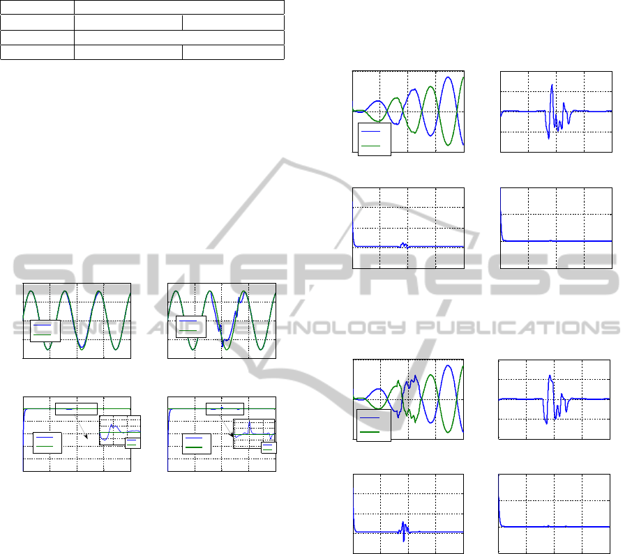
Table 1: The dynamic model.
Kinematics b = 0.35m, l = 0.25m, r = 0.2m
Dynamics Total mass = 80kg I
z
= 39.733kgm
2
Default K
1
= 7, K
22
= 10, K
21
= 200
Surface µ
1
∈ (0.2,0.4) µ
2
∈ (0.6,0.8)
I. presents the parameters used in the entire simula-
tion. In this paper, a sinusoidal waveform is supplied
to the wheelchair as the angular orientation, an incli-
nation of 10
o
and a reference linear velocity of 10m/s
is also considered. Two surface conditions are ana-
lyzed, based on the coefficient of friction of the sur-
face, we refer to these surfaces as; wet surface for
µ
1
∈ (0.2,0.4) and oily surface for µ
2
∈ (0.6,0.8).
4.1 Wet Surface (µ
1
)
0 5 10 15 20
-1
-0.5
0
0.5
1
(a). Tracking of the angular position (
µ
1
)
time (s)
Angular position
θ
(rad)
θ
θ
r
0 5 10 15 20
0
2
4
6
8
10
12
(b). Tracking of the linear velocity (
µ
1
)
time (s)
Linear velocity v (m/s)
v
v
r
0 5 10 15 20
-1
-0.5
0
0.5
1
(c). Tracking of the angular position (
µ
2
)
time (s)
Angular position
θ
(rad)
θ
θ
r
0 5 10 15 20
0
2
4
6
8
10
12
(d). Tracking of the linear velocity (
µ
2
)
time (s)
Linear velocity v (m/s)
v
v
r
8 10 12
9.98
10
10.02
10.04
time (s)
v
v
r
8 10 12
9.8
9.9
10
10.1
10.2
time (s)
v
v
r
Figure 3: Tracking of orientation and velocity of the plat-
form on wet and oily surfaces.
We use the word wet to mean a condition where only
slight slip may occur. A maximum longitudinal coef-
ficient of friction (µ
X
= 0.2) and maximum lateral co-
efficient of friction (µ
Y
= 0.4) is therefore considered
for a wet surface. In subplot (a) of fig. 3 the reference
and the output angular position of the wheelchair is
shown. It can be seen that the wheelchair tracked well
the reference angular position. The wheelchair then
slipped after the 7
th
second with the introductions of
a wet surface, and deviated a little from the reference,
however the controller still was able to track the ref-
erence orientation during the slip and perfectly after
the slip. Subplot (b) of fig. 3 shows the reference
and the output linear velocity of the wheelchair. A
perfect track of the reference linear velocity is shown
throughout the simulation except with a small devia-
tion during the period of slip, this deviation however
disappears after slip is eliminated. Torques and errors
generated by the wheelchair while moving on wet sur-
face are shown in fig. 4. It may be noticed in subplot
(a) of fig. 4 that the torques supplied to the right and
the left wheel increase in magnitudeas the wheelchair
moves uphill. This is because of the increase in the
potential energy of the wheelchair with height.
0 5 10 15 20
-5000
0
5000
(a). Torques generated by the controller
time (s)
Torques (N.m)
τ
R
τ
L
0 5 10 15 20
-0.1
-0.05
0
0.05
0.1
(c). Angular orientation error
time (s)
θ
-
θ
r
(rad)
0 5 10 15 20
-500
0
500
1000
1500
(b). Resultant torque
time (s)
τ
R
+
τ
L
(N.m)
0 5 10 15 20
-5
0
5
10
(d). Linear velocity error
time (s)
v - v
r
(m/s)
Figure 4: Torques and errors generated by the controller on
wet surface.
0 5 10 15 20
-5000
0
5000
(a). Torques generated by the controller
time (s)
Torques (N.m)
τ
R
τ
L
0 5 10 15 20
-0.4
-0.2
0
0.2
0.4
(c). Angular orientation error
time (s)
θ
-
θ
r
(rad)
0 5 10 15 20
-500
0
500
1000
1500
(b). Resultant torque
time (s)
τ
R
+
τ
L
(N.m)
0 5 10 15 20
-5
0
5
10
(d). Linear velocity error
time (s)
v-v
r
(m/s)
Figure 5: Torques and errors generated by the controller on
the oily surface.
4.2 Oily Surface (µ
2
)
The word oily is used in this paper to mean a con-
dition with increased slip. A surface with maxi-
mum longitudinal coefficient of friction (µ
X
= 0.8)
and maximum lateral coefficient of friction (µ
Y
= 0.6)
is considered as oily. Subplot (c) of fig. 3 shows
the reference and the output angular position of the
wheelchair driven on an oily surface. It can be seen
that the wheelchair tracked well the reference angu-
lar position however as compared to subplot (a) of
the same figure there was an increased deviation dur-
ing the period of slip indicating that the surface was
indeed more slippery. The controller however was
VELOCITY AND ORIENTATION CONTROL IN AN ELECTRICAL WHEELCHAIR ON AN INCLINED AND
SLIPPERY SURFACE
117

still able to track the reference orientation during the
slip and perfectly after the slip verifying the ability
of the control law developed. Subplot (d) of fig. 3
shows the reference and the output linear velocity of
the wheelchair. A perfect track of the reference lin-
ear velocity is again shown throughout the simulation
except with a small but increased deviation during the
period of slip, this deviation however disappeared af-
ter slip was eliminated. Torques and errors generated
by the wheelchair while moving on the oily surface
are shown in fig. 4.
On both surfaces, during the period of slip, irreg-
ular torques were generated to enable the platform
track closely the angular orientation and the linear ve-
locity. It may be noticed, however, that highly irreg-
ular torques were produced in subplot (a) of fig. 5
than in subplot (a) of fig. 4. This is because of the in-
creased slip on the oily surface. In subplots (c) of fig.
4 and fig. 5, the orientation tracking errors are shown
with a deviation of about 0.06 radians and 0.21 ra-
dians for wet and oily surfaces respectively. In both
cases, the error diminishes with time and the zero er-
ror is tracked the just after the 14
th
second. Little de-
viations from the referencelinear velocity v
r
may also
noticed in subplots (d) of fig. 4 and fig. 5 during the
slip.
4.3 Conclusions
The dynamic model of a wheelchair has been devel-
oped in this paper in such a way that the wheelchair
movement is not restricted to flat surfaces alone. The
model developed here include effects of frictional
forces, gravitational forces and slip. Navigation of
wheelchair by tracking velocity and orientation is also
investigated. A nonlinear feedback law that links the
reference linear velocity (v
r
) and reference angular
orientation (θ
r
) supplied to the controller is devel-
oped with satisfactory results. Torques supplied to
the plant during navigation are also analysed with the
result that irregular torques are supplied during slip.
Extensivecomputersimulationsare then performedto
verify the usefulness of the designed model and con-
troller.
4.4 Future Works
It has been realized that torquessupplied to the wheels
increases with time as the wheelchair moves up-
hill, future work may therefore involve limiting the
torques supplied to the wheels to a values that may be
contained by the supplying battery.
Future work will also involve inclusion of assis-
tive controller to help the wheelchair make realtime
decision in cases where the patient is either unable to
or is slow to make such decisions.
Filtering of undesired error signals that might be
sent to the controller by severely and shaking dis-
abled wheelchair users and implementation of this
controller on the FSATIE wheelchair platform are
some of the future works.
ACKNOWLEDGEMENTS
The authors of this paper gratefully appreciate the
contribution of Tshwane University of Technology
and F’SATIE for providing relevant and necessary
support for this research.
REFERENCES
Dixon, W., Walker, I., and Dawson, D. (2001). Fault detec-
tion for wheeled mobile robots with parametric uncer-
tainty. IEEUASME International Conference on Ad-
vanced Intelligent Mechatronics Proceedings, pages
1245 – 1250.
Feng, C. and Fei, S. (1998). Analysis and design of nonlin-
ear control system. Publishing House of Electronics
Industry, Beijing.
Fierro, R. and Lewis, F. (1997). Control of a nonholonomic
mobile robot: Backstepping kinematics into dynam-
ics. Journal of Robotic Systems, 14(3):149 – 164.
Ge, S. and Lewis, F. (2006). Autonomous mobile robots;
sensing, control, decision making and applications.
Taylor and Francis Group LLC,.
Hamed, E., Yskandar, H., Eric, M., and Imad, M. (2007).
Dynamic model of electrical wheelchair with slipping
detection. EUROSIM, pages 1 – 6.
Isidori, A. (1995). Nonlinear Control Systems. Birkhuser,
3 edition.
Khalil, H. (1996). Nonlinear Systems. Prentice Hall, New
Jersey.
Kozlowski, K. and Pazderski, D. (2004). Modeling and con-
trol of a 4-wheel skid steering mobile robot. Interna-
tional Journal of Applied Mathematics and Computer
Science, 14(4):477 – 496.
Motte, I. and Guy, C. (2000). A slow manifold approach for
the control of mobile robots not satisfying the kine-
matic constraints. IEEE Transaction on Robotics and
Automation, 16(6):875 – 880.
Ortega, R., der Schaft, A. V., Mareels, I., and Maschke,
B. (2000). Energy shaping revisited. In IEEE Inter-
national Conference on Control Applications, pages
121–125, Anchorage USA.
Sidek, S. N. (2008). Dynamic Modeling and Control of
Nonholonomic Wheeled Mobile Robot Subjected To
Wheel Slip. PhD thesis, Graduate School of Vanderbilt
University.
ICINCO 2011 - 8th International Conference on Informatics in Control, Automation and Robotics
118

Slotine, J. and Li, W. (1991). Applied nonlinear control.
Prentice-Hall, Englewood Cliffs,NJ.
Spong, M. W., Hutchinson, S., and Vidyasagar, M. (1989).
Robot Modeling and Control. John Wiley & Sons, Inc,
1 edition.
Stonier, D., Cho, S.-H., Choi, S.-L., Suresh, K. N., and
Jong-Hwan, K. (2007). Nonlinear slip dynamics for
an omniwheel mobile robot platform. IEEE Interna-
tional Conference on Robotics and Automation, pages
2367 – 2372.
Tarokh, M. and McDermott, G. J. (2005). Kinematics mod-
eling and analyses of articulated rovers. IEEE Trans-
actions on Robotics, 21(4):539 – 553.
Vignier, N., Ravaud, J.-F., Myriam, W., Franois-Xavier, L.,
and Ville, I. (2008). Demographics of wheelchair
users in france: Results of national community based
handicaps in capabilities dependence surveys. Jour-
nal of Rehabilitation Medicine, pages 231 – 239.
Wells, D. (1967). Problems of Lagrangian Dynamics
Schausms Outline Series. McGraw Hill Company,
New York, 1st edition edition.
Williams, R. L., Carter, B. E., Paolo, G., and Giulio, R.
(2002). Dynamic model with slip for wheeled omni-
directional robots. IEEE Transaction on Robotics and
Automation, 18(3):285 – 292.
Wobbrock, J. O., Myers, B. A., Htet, A. H., and LoPresti,
E. F. (2004). Text entry from power wheelchairs:
Edgewrite for joysticks and touchpads. ACM, pages
110 – 117.
Woude, L. V. D., Groot, S. D., and Janssen, T. (2006). Man-
ual wheelchairs: research and innovation in sports and
daily life. Elsevier, pages 226 – 235.
Zhu, X., Dong, G., Hu, D., and Cai, Z. (2006). Robust
tracking control of wheeled mobile robots not satis-
fying nonholonomic constraints. Proceedings of the
Sixth International Conference on Intelligent Systems
Design and Applications (ISDA’06), page 6.
VELOCITY AND ORIENTATION CONTROL IN AN ELECTRICAL WHEELCHAIR ON AN INCLINED AND
SLIPPERY SURFACE
119
