OBSTACLE AVOIDANCE WITH SIMULTANEOUS
TRANSLATIONAL AND ROTATIONAL MOTION CONTROL
FOR AUTONOMOUS MOBILE ROBOT
Masaki Takahashi, Takafumi Suzuki, Tetsuya Matsumura and Ayanori Yorozu
Dept. of System Design Engineering, Keio University, 3-14-1 Hiyoshi, Kohoku-ku, Yokohama 223-8522, Japan
Keywords: Service Robot, Obstacle Avoidance, Omni-directional Platform, Fuzzy Potential Method.
Abstract: This paper presents a real-time collision avoidance method with simultaneous control of both translational
and rotational motion with consideration of a robot width for an autonomous omni-directional mobile robot.
In the method, to take into consideration the robot’s size, a wide robot is regarded as a capsule-shaped case
not a circle. With the proposed method, the wide robot can decide the direction of translational motion to
avoid obstacles safely. In addition, the robot can decide the direction of the rotational motion in real time
according to the situation to perform smooth motion. As an example of design method of the proposed
method, novel control method based on the fuzzy potential method is proposed. To verify its effectiveness,
several simulations and experiments using a real robot are carried out.
1 INTRODUCTION
Various obstacle avoidance methods and their
availabilities for mobile robots have described (Du,
2007)-(Dieter, 1997). Most of these studies regard
the robots as points or circles and discuss control
methods of translational motion. In these studies, a
non-circle robot is regarded as a circle robot with
consideration of maximum size of the robot. The
effectiveness of avoiding obstacles by this approach
has been confirmed. However, depending on the
shape of the robot, this approach reduces and wastes
available free space and can decrease the possibility
that the robot reaches the goal. If wide robots, which
are horizontally long, are regarded as circles in
accordance with conventional approaches, they may
not be able to go between two objects due to the
largest radius of the robot, even if they ought to be
able to go through by using their shortest radius.
This suggests the necessity of a suitable orientation
angle at the moment of avoidance. Consequently, to
enable wide robots to avoid obstacles safely and
efficiently, it is necessary to control not only a
translational motion but also a rotational motion. In
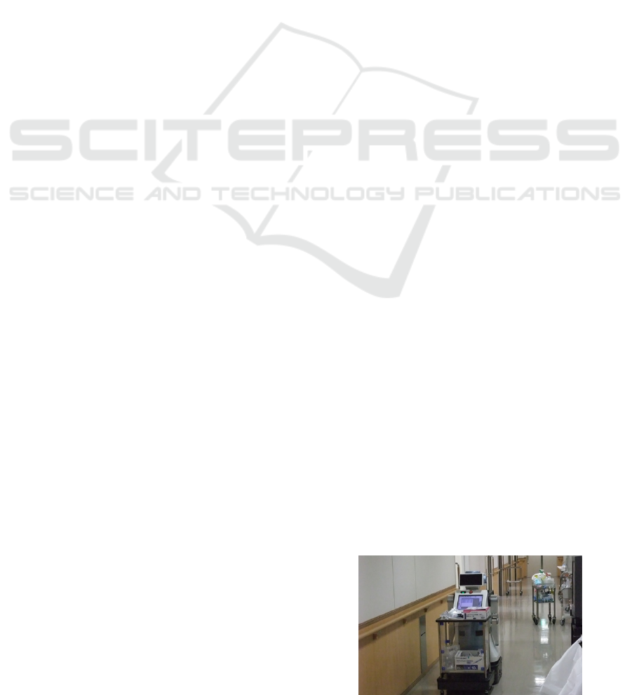
our current research, a wide robot with omni-
directional platforms shown in Figure 1 is
developed.
Several studies have focused on the orientation
angle of the robot (Kavraki, 1995)(Wang and
Chirikjian, 2000). In these studies, by convolving the
robot and the obstacle at every orientation and
constructing the C-space, the suitable orientation
angles of the robot for path planning are decided.
However, these methods require an environmental
map and the studies have not shown the
effectiveness for avoidance of unknown obstacles by
autonomous mobile robots. Therefore, to avoid
unknown obstacles reactively with consideration of
the orientation angle, wide robots need an algorithm
that can decide the orientation angle and rotational
velocity command in real time based on current
obstacle information.
This study proposes a control method of both
translational and rotational motion with
consideration of a robot width in order to achieve a
smooth motion. With the proposed method, the
Figure 1: An autonomous robot for hospital use.
5
Takahashi M., Suzuki T., Matsumura T. and Yorozu A..
OBSTACLE AVOIDANCE WITH SIMULTANEOUS TRANSLATIONAL AND ROTATIONAL MOTION CONTROL FOR AUTONOMOUS MOBILE ROBOT.
DOI: 10.5220/0003443300050013
In Proceedings of the 8th International Conference on Informatics in Control, Automation and Robotics (ICINCO-2011), pages 5-13
ISBN: 978-989-8425-75-1
Copyright
c
2011 SCITEPRESS (Science and Technology Publications, Lda.)
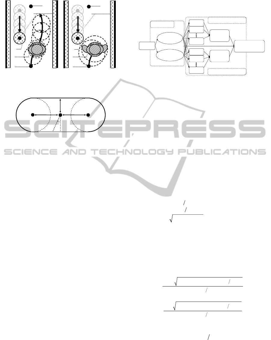
(a) Situation A (b) Situation B
Figure 2: Two robots which are included in respective
circles.
Figure 3: Capsule-shaped case.
orientation angle is controlled easily in real time. To
verify the effectiveness of the proposed method,
several simulations and experiments using our robot
shown in Figure 1 are carried out.
2 SIMULTANEOUS
TRANSLATIONAL
AND ROTATIONAL MOTION
CONTROL
2.1 Problem for Solution
There are various non-circle robots. These are
vertically long robots, or wide robots. These robots
have two arms mounted on a torso with wheels so
these robots can be used for mobility, manipulation,
whole-body activities, and human-robot interaction
(Ambrose, 2004)(Takahashi, 2009). For these wide
robots, conventional obstacle avoidance methods are
incompatible because they regard the robot as a point
or a circle. We are developing a wide robot with a
torso, two arms and a head shown in Figure 1. It not
only moves indoors but also communicates and
interacts with humans through gestures or speech.
When the robot opens one or both of its arms
slightly, as shown in Figure 2(b), it becomes
increasingly difficult to apply conventional obstacle
avoidance methods. If these wide robots are regarded
as circles in accordance with conventional
approaches, it may not be possible for them to go
between two obstacles due to the largest radius of
the robot, even if they
Figure 4: Concept of fuzzy potential method using both
translational and rotational motion with an omni-direction
platform.
ought to go through by using their shortest radius. In
this study, a capsule-shaped case is introduced to
make wide robots move smoothly and safely in an
environment with obstacles.
2.2 Design of Capsule-shaped Case
The capsule-shaped case is modeled by two circles
and two lines tangent to the circles as shown in
Figure 3. This closed contour is defined as
()l
φ
with
the origin at the point
P
O
.
()
() ()
1
4
23
22
12
34
0
cos
2
cos
a
a
Cif
lC if
XYif
φ
φ
φ
φ
φπ
φφ
φ
φφ
φ
φφ
φφ
φ
φφ
≤<
⎧
≤<
⎪
⎪
=−
≤<
⎨
⎪
≤<
+
⎪
⎩
≤<
(1)
where
i
φ
is clockwise from the back direction of the
robot.
12
arctan( / ), arctan( / ),
La La
CC CC
φ
φπ
=
=−
34
arctan( / ), 2 arctan( / )
R
aRa
CC CC
φ
πφπ
=
+=−
()X
φ
and
()Y
φ
are calculated as follows.
()
()
()
{}
()
()
()
{}
()
222
2
2
12
222
2
2
34
1tan 2
1tan 2
1tan 2
1tan 2
LLLa
RRRa
CCCC
if
X
CCCC
if
π
φ
πφ
φφφ
φ
π
φ
πφ
φφφ
⎧
−− − − + −
⎪
⎪
+−
⎪
⎪
≤<
⎪
=
⎨
⎪
+−− + −
⎪
⎪
+−
⎪
≤<
⎪
⎩
(2)
(
)
(
)
(
)
tan 2YX
φ
φπφ
=
−
(3)
In the proposed method,
L
C
,
R
C
,and
a
C
are decided
in a way that makes wide robot shape fall within the
capsule-shaped case.
Obstacle
Goal
Start
Robot
s
d
Obstacle
Goal
Start
Robot
s
d
Obstacle
Goal
Start
Robot
s
d
Obstacle
Goal
Start
Robot
s
d
P
R
P
L
P
O
a
C
R
C
L
C
φ
P
R
P
L
P
O
a
C
R
C
L
C
P
R
P
L
P
O
a
C
R
C
L
C
φ
PMF 1
PMF 2
PMF i
PMF 1
PMF 2
PMF j
Environment
Own condition
Fuzzy
operation
Fuzzy
operation
Omni-directional
drive system
Rotational motion
Translational motion
Information
Sensors
ICINCO 2011 - 8th International Conference on Informatics in Control, Automation and Robotics
6
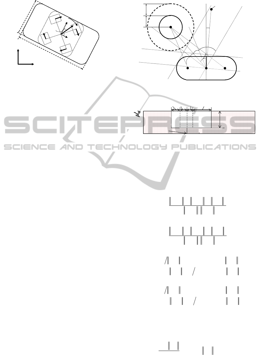
Figure 5: Omni-directional platform with wide body.
2.3 Controller Design
Figure 4 shows a concept of the fuzzy potential
method (FPM) that takes into consideration both
translational and rotational motion. In the
conventional FPM (Tsuzaki, 2003), a command
velocity vector that takes into consideration element
actions is decided. Element actions are represented
as potential membership functions (PMFs), and then
they are integrated by means of fuzzy inference. The
horizontal axis of PMF is directions which are from
π
−
to
π
radians measured clockwise from the front
direction of the robot. The vertical axis of PMF is
the grade for the direction. The grade, direction, and
configured maximum and minimum speeds, are used
to calculate the command velocity vector.
In this research, in addition to conventional
approach the PMFs for translational and rotational
motion are designed respectively based not only on
environmental information but also the robot's
condition. Environmental information and the robot's
condition are treated separately and divided into a
translation problem and a rotational problem. Then
the PMFs of each problem are independently
integrated using fuzzy inference. Finally,
translational and rotational velocity commands,
which are calculated by defuzzification of mixed
PMFs, are realized by an omni-directional drive
system, as shown in Figure 5.
2.4 PMF for Translational Motion
2.4.1 PMF for Obstacles
To enable a wide robot to avoid obstacles safely and
efficiently in real time, a concave shaped PMF
(1,2,,)
t
oj
j
n
μ
= "
shown in Figure 7, which takes into
consideration the capsule case, is generated. This
PMF is specified by depth and width, which are
calculated based on the geometrical relation between
an obstacle and the robot as shown in Figure 6. By
Figure 6: Wide robot and obstacle.
Figure 7: Example of PMF for an obstacle
generating a PMF based on the variables
L
ϕ
,
R
ϕ
,
L
ϕ
′
,
R
ϕ
′
, a and
,ro
ϕ
in Figure 7, it can choose a safe
direction.
222
PQ PQ PP
arccos .
2PQ PQ
OO LO OL
L
OO LO
ϕ
⎛⎞
+−
⎜⎟
=
⎜⎟
⋅
⎜⎟
⎝⎠
J
JJJJJG JJJJJJGJJJJJG
JJJJJJG JJJJJJG
(4)
222
PQ PQ PP
arccos .
2PQ PQ
OO RO OR
R
OO RO
ϕ
⎛⎞
+−
⎜⎟
=
⎜⎟
⋅
⎜⎟
⎝⎠
J
JJJJJG JJJJJJG JJJJJG
JJJJJJG JJJJJJG
(5)
(
)
()
()
{}
arcsin P Q P Q .
arcsin P Q P Q .
LO LO
L
LO s s LO
DifD
dDdifD
ϕ
π
⎧
<
⎪
′
=
⎨
⎪
−−−≥
⎩
J
JJJJJG JJJJJJG
J
JJJJJG JJJJJJG
(6)
(
)
()
()
{}
arcsin P Q P Q .
arcsin P Q P Q .
RO RO
R
RO s s RO
DifD
dDdifD
ϕ
π
⎧
<
⎪
′
=
⎨
⎪
−−−≥
⎩
J
JJJJJG JJJJJJG
J
JJJJJG JJJJJJG
(7)
As a measure to decide how far the robot should
depart from the obstacle,
a
is defined as the depth of
the concave PMF.
,
,
.
ro
ro
aif
D
α
α
α
−
=<
−
r
r
(8)
y
x
δ
out
v
2
w
v
1
w
v
4
w
v
3
w
v
y
r
v
x
r
v
ω
out
ϕ
R
W
L
y
x
δ
out
v
2
w
v
1
w
v
4
w
v
3
w
v
y
r
v
x
r
v
ω
out
ϕ
RR
W
LL
Obstacle
P
R
P
L
P
O
L
ϕ
R
ϕ
L
ϕ
′
R
ϕ
′
Q
O
o
r
s
d
,ro
ϕ
Capsule Case
Goal or Subgoal
,rg
ϕ
Obstacle
P
R
P
L
P
O
L
ϕ
R
ϕ
L
ϕ
′
R
ϕ
′
Q
O
o
r
s
d
,ro
ϕ
Capsule Case
Goal or Subgoal
,rg
ϕ
grade
0
1
0
direction [rad]
R
ϕ
′
ϕ
,ro
ϕ
R
ϕ
L
ϕ
L
ϕ
′
a
π
π
−
OBSTACLE AVOIDANCE WITH SIMULTANEOUS TRANSLATIONAL AND ROTATIONAL MOTION CONTROL
FOR AUTONOMOUS MOBILE ROBOT
7
where
,
(r ,r )
ro x y
=r
is the current position vector of
the obstacle relative to the robot. If the current
obstacle position is inside a circle with radius
α
from the robot position, a PMF for obstacle
avoidance is generated.
D
is decided to ensure a
safe distance.
.
ao s
DC r d=++
(9)
a
C is the minimum size of the capsule case,
o
r and
s
d denote respectively the radius of the obstacle and
the safe distance.
,ro
ϕ
is the angle of the direction to
the obstacle relative to the robot.
,
arctan(r / r ) .
ro y x
ϕ
=
(10)
For safe avoidance, the PMF
t
oj
μ
is generated for
all the obstacles that the robot has detected. Then,
they are all integrated by calculating the logical
product
t
o
μ
.
12
.
tt t t
oo o oj
μμ μ μ
=∧∧⋅⋅⋅∧
(11)
By deciding the depth and the base width of the
concave PMF
t
o
μ
is generated.
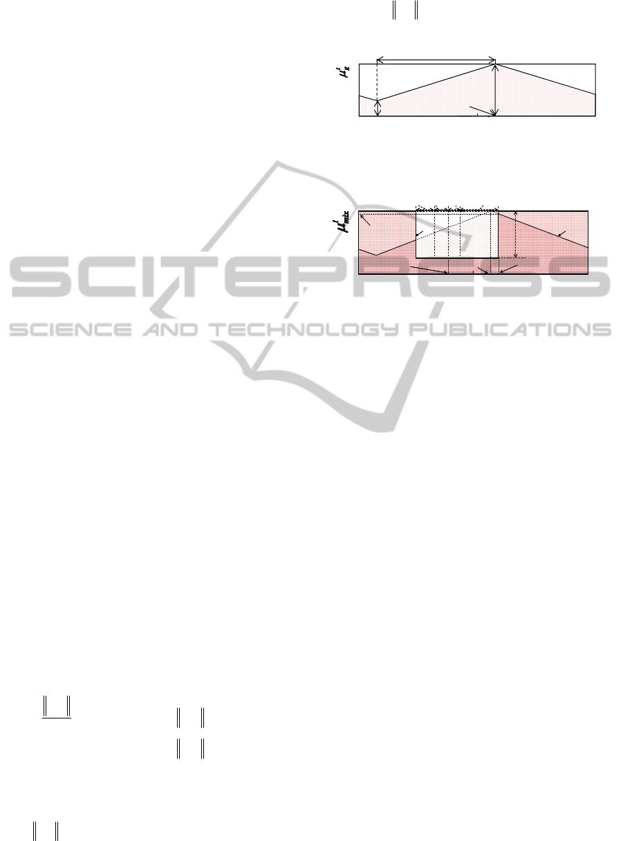
2.4.2 PMF for a Goal
To head to the goal, a triangular PMF
t
g
μ
is
generated, as shown in Figure 8.
t
g
μ
is specified by
a
g
,
b
g
,and
,rg
ϕ
. As a measure to decide how close
to the goal the robot should go,
a
g
is defined as the
height of the triangular PMF. As a measure to decide
how much the robot can back away from obstacles,
b
g
is defined.
t
g
μ
reaches the maximum value as
a
g
at an angle of the goal direction relative to the
front direction of the robot
,rg
ϕ
.
,
,
,
.
1.0
rg
rg
a
rg
if
g
if
ε
ε
ε
⎧
⎪
≤
=
⎨
⎪
>
⎩
r
r
r
(12)
(
)
01 .
ba
gg
ηη
=≤<
(13)
where
,rd
r
is an absolute value of the position
vector of the goal relative to the robot.
ε
and
η
are
constants. If
,rd
r
is below
ε
,
a
g
is defined. The
robot can decelerate and stop stably.
Figure 8: Example of PMF for a goal.
Figure 9: Example of mixed PMF for translational motion.
2.4.3 Calculation of a Translational
Command Velocity Vector
The proposed method uses fuzzy inference to
calculate the command velocity vector. The PMFs
t
o
μ
and
t
g
μ
are integrated by fuzzy operation into a
mixed PMF
t
mix
μ
as shown in Figure 9.
t
mix
μ
is an
algebraic product of
t
o
μ
and
t
g
μ
.
.
ttt
mix g o
μ
μμ
=∧
(14)
By defuzzifier, a velocity command vector is
calculated as a traveling direction
out
ϕ
and an
absolute value of the reference speed of the robot
based on the mixed PMF
t
mix
μ
.
out
ϕ
is decided as the
direction that makes the PMF
()
t
mix
μ
ϕ
maximum.
Based on
out
ϕ
,
out
v is calculated as follows.
()( )
t
out mix out max min min
vvvv .
μϕ
=−+
(15)
where
()
t
mix out
μϕ
is the mixed PMF for translational
motion corresponding to the
out
ϕ
.
max
v and
min
v are
respectively the upper and lower limits of the robot
speed.
0
1
0
a
g
b
g
,rg
ϕ
π
π
−
π
grade
direction [rad]
ϕ
out
ϕ
(
)
t
mix out
μϕ
0
1
0
π
−
π
grade
direction [rad]
ϕ
L
ϕ
R
ϕ
L
ϕ
′
R
ϕ
′
,ro
ϕ
a
t
g
μ
t
o
μ
,rg
ϕ
out
ϕ
(
)
t
mix out
μϕ
0
1
0
π
−
π
grade
direction [rad]
ϕ
L
ϕ
R
ϕ
L
ϕ
′
R
ϕ
′
,ro
ϕ
a
t
g
μ
t
o
μ
,rg
ϕ
ICINCO 2011 - 8th International Conference on Informatics in Control, Automation and Robotics
8

2.5 PMF for Rotational Motion
2.5.1 PMF for Obstacles
To enable a wide robot to decide the appropriate
angle of the direction for obstacle avoidance in real
time, PMF
r
o
μ
is generated.
.
rrr
oec
μ
μμ
=−
(16)
Figure 10: Example of mixed PMF for rotational motion.
r
e
μ
is generated based on the distance from the
center of the robot to obstacles corresponding to all
directions, as shown in Figure 10. The relative
distances are obtained with range sensors such as
laser range finder, ultra sonic sensors or infrared
sensors.
r
c
μ
is generated based on the capsule case.
()
(
)
.
r
c
l
ϕ
π
μϕ
α
+
=
(17)
The aim of the PMF
r
o
μ
is to search for an
orientation angle of the robot that would maximize
the distance between a point on capsule case and
each obstacle by turning the front or back side of the
robot. By using the capsule case, a PMF design can
deal with the width of the robot for rotational motion.
2.5.2 PMF for a Goal
In order to turn the front of the robot toward the goal
direction or the travelling direction if there is no
obstacle to avoid, PMF for a goal is generated as
r
g
μ
.
This shape is decided in same way as
t
g
μ
.
2.5.3 Calculation of a Rotational Command
Velocity
For the rotational motion, like the translational
motion, the rotational command velocity is derived.
The PMFs
r
e
μ
and
r
g
μ
are integrated by fuzzy
operation into a mixed PMF
r
mix
μ
, as shown in
Figure 10.
.
rrr
mix g o
μμμ
=∧
(18)
By defuzzifier, the command velocity is
calculated as a rotational direction
ori
ϕ
and an
absolute value of the reference speed of the robot.
ori
ϕ
is decided as the direction
i
ϕ
that makes the
following function
()h
ϕ
minimum.
() ()
r
mix
h d
ϕζ
ϕζ
ϕ
μψψ
+
−
=
∫
(19)
where
ζ
is the parameter to avoid choosing an
uncertainty
i
ϕ
caused by, for example, noise on the
sensor data. On the basis of
ori
ϕ
,
ω
is calculated.
Table 1: Parameters in numerical simulations.
L 0.4 m W 1.0 m
C
a
0.3 m C
L
0.3 m
C
R
0.3 m r
a
0.3 m
d
s
0.3 m D 0.9 m
α
4.0 m
η
0.2
ε
1.0 m a
r
1.0 m/s
2
ω
max
1.0 rad/s
ω
min
0.0 rad/s
sgn( )
a ori
.
ω
ωϕ
=
(20)
where
a
ω
is design variable.
2.6 Omni-directional Platform
An omni-directional platform was used for the
autonomous mobile robot's motion. The command
velocity vector was realized by four DC motors and
omni wheels.
cos .
x
r out out
vv
ϕ
=
(21)
sin
y
r out out
vv
ϕ
=
(22)
where
out
v and
ω
are respectively command
translational velocity vector and rotational velocity.
1
2
3
4
cos sin
cos sin
cos sin
cos sin
w
x
r
w
y
r
w
w
v
R
v
v
R
v
R
v
R
v
δδ
δδ
δδ
ω
δδ
⎡⎤
⎡⎤
⎡⎤
⎢⎥
⎢⎥
⎢⎥
−
⎢⎥
⎢⎥
=
⎢⎥
⎢⎥
⎢⎥
−−
⎢⎥
⎢⎥
⎢⎥
⎢⎥
⎣⎦
⎢⎥
−
⎢⎥
⎣⎦
⎣⎦
(23)
δ
is an angle of gradient for each wheel.
R
is half
r
e
μ
r
c
μ
0
1
0
π
−
π
grade
direction [rad]
ϕ
r
o
μ
(
)
r
mix ori
μ
ϕ
ori
ϕ
r
e
μ
r
c
μ
0
1
0
π
−
π
grade
direction [rad]
ϕ
r
o
μ
(
)
r
mix ori
μ
ϕ
ori
ϕ
OBSTACLE AVOIDANCE WITH SIMULTANEOUS TRANSLATIONAL AND ROTATIONAL MOTION CONTROL
FOR AUTONOMOUS MOBILE ROBOT
9
the distance between two diagonal wheels.
w
i
v
is a
command velocity of each
-thi
wheel.
3 SIMULATION RESULTS
To verify the effectiveness of the proposed method,
numerical simulations were carried out. In
simulations, the robot was presumed to be able to
detect obstacles and to have information about the
relative position vector. The measuring range was
assumed to be 4.0 m in all directions. Each
parameter was shown in Table 1.
(a) Situation I.
(b) Situation II.
Figure 11: Simulation results.
(a) Situation I: robot cannot find the direction between the
two obstacles.
(b) Situation II: robot can find the direction between the
two obstacles.
Figure 12: Aspects of mixed PMF for translational motion
in two different situations.
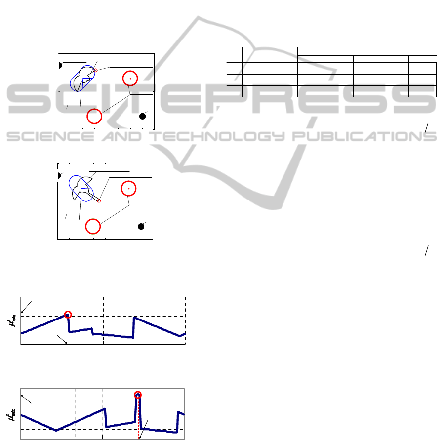
3.1 Performance of Capsule Case
To verify the effectivenesses of using capsule case
by comparing the results of the chosen direction of
robot motion, simulations in two different situations
regarding the orientation angle for a wide robot were
carried out. In the simulations, the positions of the
robot and two obstacles were immobilized at each
point respectively
(1.0 m, 2.0 m) , (1.5 m, 0.5 m) and
(3.0 m, 2.0 m) , as shown in Figure 11.
Table 2: Position coordinates of start and goal points of the
robot and of obstacles.
In situation I shown in Figure 11(a), the
orientation angle of the robot was fixed to
4
π
−
radians clockwise from the x-axis on the absolute
coordinates. Therefore the robot faced the goal.
Figure 12(a) shows the mixed PMF
t
mix
μ
in this
situation. The chosen direction of the robot motion
was calculated as
1.35
−
radians, which was
clockwise from the front direction of the robot, as
shown in Figure 11(a). As a result, the robot chose a
longer route to the goal.
In situation II shown in Figure 11(b), the
orientation angle of the robot was fixed to
4
π
radians on the absolute coordinates. In contract to
situation I, the robot did not face the goal. Figure
12(b) shows the mixed PMF
t
mix
μ
in this situation.
The chosen direction of the robot motion was
calculated as
1.37
radians, which was clockwise
from the front direction of the robot, as shown in
Figure 11(b). As a result, the robot chose a shorter
route with no collision.
These two results showed the effectiveness of the
capsule case and that the wide robot can decide the
direction of translational motion that takes
consideration with the robot's orientation, the goal
position and the obstacle position simultaneously in
real time.
3.2 Obstacle Avoidance
The effectiveness of the proposed method was
verified by comparing two design methods based on
FPM in three situations. In method I, the wide robot
was regarded as a circle with radius 0.6 m. In
0 1.0 2.0 3.0 4.
0
0
1.0
2.0
3.0
x-coordinate [m]
y-coordinate [m]
x
y
Goal point
Start point
Obstacle
Robot
mixed PMF :
Selected direction
t
mix
μ
(
)
4 rad
π
−
0 1.0 2.0 3.0 4.
0
0
1.0
2.0
3.0
x-coordinate [m]
y-coordinate [m]
x
y
0 1.0 2.0 3.0 4.
0
0
1.0
2.0
3.0
x-coordinate [m]
y-coordinate [m]
x
y
0 1.0 2.0 3.0 4.
0
0
1.0
2.0
3.0
x-coordinate [m]
y-coordinate [m]
xx
yy
Goal point
Start point
Obstacle
Robot
mixed PMF :
Selected direction
t
mix
μ
(
)
4 rad
π
−
0000
0 1.0 2.0 3.0 4.0
0
1.0
2.0
3.0
x-coordinate [m]
y-coordinate [m]
x
y
Goal point
Start point
Obstacle
Robot
mixed PMF :
Selected direction
t
mix
μ
(
)
4 rad
π
0 1.0 2.0 3.0 4.0
0
1.0
2.0
3.0
x-coordinate [m]
y-coordinate [m]
x
y
0 1.0 2.0 3.0 4.0
0
1.0
2.0
3.0
x-coordinate [m]
y-coordinate [m]
x
y
0 1.0 2.0 3.0 4.0
0
1.0
2.0
3.0
x-coordinate [m]
y-coordinate [m]
x
y
0 1.0 2.0 3.0 4.0
0
1.0
2.0
3.0
x-coordinate [m]
y-coordinate [m]
xx
yy
Goal point
Start point
Obstacle
Robot
mixed PMF :
Selected direction
t
mix
μ
(
)
4 rad
π
0
1
0
π
−
π
()
t
mix out
μϕ
out
ϕ
direction
[
rad
]
ϕ
0
1
0
π
−
π
()
t
mix out
μϕ
out
ϕ
direction
[
rad
]
ϕ
0
1
0
π
−
π
()
t
mix out
μϕ
out
ϕ
direction
[
rad
]
ϕ
0
1
0
π
−
π
()
t
mix out
μϕ
out
ϕ
direction
[
rad
]
ϕ
Start [m] Goal [m]
(2.5, 1.8)− (2.5, 1.2)− (2.5,1.2) (2.5,1.8)(0.0,0.0) (8.0,0.0)
(0.0, 2.0)− (11, 2.0)
Obstacles [m]
A
B
C
(0.0, 2.0)− (11, 2.0)
(4.0, 2.0)− (4.0, 1.4)− (4.0,1.0) (4.0,1.6)
123
4
(4.0, 2.0)− (4.0, 1.4)− (4.0, 0.4) (4.0,1.0)
5
−
(4.0, 2.2)
(4.0,1.6)
Start [m] Goal [m]
(2.5, 1.8)− (2.5, 1.2)− (2.5,1.2) (2.5,1.8)(0.0,0.0) (8.0,0.0)
(0.0, 2.0)− (11, 2.0)
Obstacles [m]
A
B
C
(0.0, 2.0)− (11, 2.0)
(4.0, 2.0)− (4.0, 1.4)− (4.0,1.0) (4.0,1.6)
123
4
(4.0, 2.0)− (4.0, 1.4)− (4.0, 0.4) (4.0,1.0)
5
−
(4.0, 2.2)
(4.0,1.6)
ICINCO 2011 - 8th International Conference on Informatics in Control, Automation and Robotics
10
method II, the capsule case was used and the width
and rotational motion of the robot were taken into
consideration. The start and goal positions of the
robot and the obstacles are shown in Table 2.
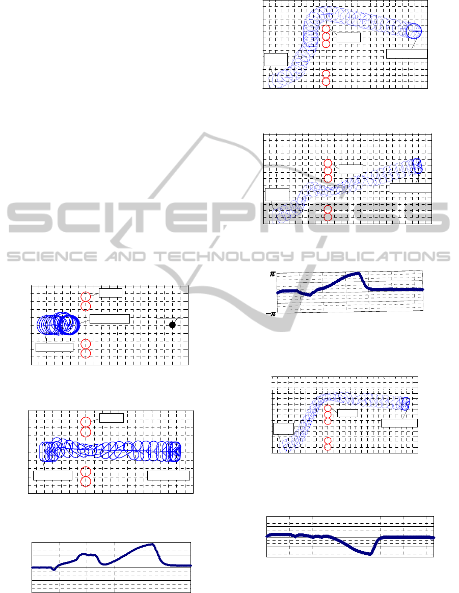
In situation A, the robot with method I did not
succeed in going between two objects. It did not
collide with the obstacles and did not get to the goal
point as shown in Figure 13. On the other hand, in
method II, the capsule case and real-time control
based on FPM were used. As shown in Figure 14,
the robot performed translational and rotational
motion simultaneously in real time and succeeded in
going between two objects. Figure 15 shows the time
history of the orientation angle on the absolute
coordinate of the robot. The robot changed the
orientation angle according to the situations and
succeeded in getting to the goal with the orientation
angle 0 radian by using PMF for rotational motion.
In situation B, the robot with method II did not
succeeded to going between two objects as shown in
Figure 16. The robot found another way and got to
the goal point. On the other hand, as shown in Figure
17, the robot with method II performed translational
and rotational motion simultaneously in real time.
Figure 13: Simulation result of method I in situation A.
Figure 14: Simulation result of method II in situation A.
Figure 15: Orientation angle of the robot with method II in
situation A.
Figure 16: Simulation result of method I in situation B.
Figure 17: Simulation result of method II in situation B.
Figure 18: Orientation angle of the robot with method II in
situation B.
Figure 19: A simulation result in the situation C by using
method II.
Figure 20: Orientation angle of the robot with method II in
situation C.
The time history of the orientation angle on the
absolute coordinates of the robot is shown in Figure 18.
-1.0 0 1.0 2.0 3.0 4.0 5.0 6.0 7.0 8.0 9.0
-2.0
-1.0
0
1.0
2.0
x-coordinate [m]
y-coordinate [m]
Obstacle
Robot : t = 0.0s
Robot : t = 24.7s
Goal point
x [m]
y [m]
-1.0 0 1.0 2.0 3.0 4.0 5.0 6.0 7.0 8.0 9.0
-2.0
-1.0
0
1.0
2.0
x-coordinate [m]
y-coordinate [m]
Obstacle
Robot : t = 0.0s
Robot : t = 24.7s
Goal point
-1.0 0 1.0 2.0 3.0 4.0 5.0 6.0 7.0 8.0 9.0
-2.0
-1.0
0
1.0
2.0
x-coordinate [m]
y-coordinate [m]
Obstacle
Robot : t = 0.0s
Robot : t = 24.7s
-1.0 0 1.0 2.0 3.0 4.0 5.0 6.0 7.0 8.0 9.0
-2.0
-1.0
0
1.0
2.0
x-coordinate [m]
y-coordinate [m]
Obstacle
Robot : t = 0.0s
Robot : t = 24.7s
Goal point
x [m]
y [m]
-1.0 0 1.0 2.0 3.0 4.0 5.0 6.0 7.0 8.0 9.0
-2.0
-1.0
0
1.0
2.0
x-coordinate [m]
y-coordinate [m]
Obstacle
Robot : t = 0.0s Robot : t = 24.7s
x [m]
y [m]
-1.0 0 1.0 2.0 3.0 4.0 5.0 6.0 7.0 8.0 9.0
-2.0
-1.0
0
1.0
2.0
x-coordinate [m]
y-coordinate [m]
Obstacle
Robot : t = 0.0s Robot : t = 24.7s
-1.0 0 1.0 2.0 3.0 4.0 5.0 6.0 7.0 8.0 9.0
-2.0
-1.0
0
1.0
2.0
x-coordinate [m]
y-coordinate [m]
Obstacle
Robot : t = 0.0s Robot : t = 24.7s
x [m]
y [m]
time
[
s
]
0 5 10 15 20 25
orientation angle [rad]
π
π
−
0
time
[
s
]
0 5 10 15 20 25
orientation angle [rad]
π
π
−
0
-1 0 1 2 3 4 5 6 7 8 9 10 11 12
-2
-1
0
1
2
3
4
x
-coordinate
[
m
]
y-coordinate [m]
Obstacle
Robot : t = 42.2s
: t = 0.0s
Robot
1
O
2
O
3
O
4
O
5
O
-1 0 1 2 3 4 5 6 7 8 9 10 11 12
-2
-1
0
1
2
3
4
x
-coordinate
[
m
]
y-coordinate [m]
Obstacle
Robot : t = 42.2s
: t = 0.0s
Robot
-1 0 1 2 3 4 5 6 7 8 9 10 11 12
-2
-1
0
1
2
3
4
x
-coordinate
[
m
]
y-coordinate [m]
Obstacle
Robot : t = 42.2s
: t = 0.0s
Robot
: t = 0.0s
Robot
1
O
2
O
3
O
4
O
5
O
-1 0 1 2 3 4 5 6 7 8 9 10 11 12
-2
-1
0
1
2
3
4
x
-coordinate
[
m
]
y-coordinate [m]
1
O
2
O
3
O
4
O
5
O
Obstacle
Robot : t = 31.8s
: t = 0.0s
Robot
-1 0 1 2 3 4 5 6 7 8 9 10 11 12
-2
-1
0
1
2
3
4
x
-coordinate
[
m
]
y-coordinate [m]
1
O
2
O
3
O
4
O
5
O
Obstacle
Robot : t = 31.8s
: t = 0.0s
Robot
: t = 0.0s
Robot
t
i
m
e
[
s
]
0
5
1
0
1
5
20
2
5
o
r
i
e
n
t
a
t
i
o
n
a
n
gl
e
[
r
a
d
]
0
3
0
t
i
m
e
[
s
]
0
5
1
0
1
5
20
2
5
o
r
i
e
n
t
a
t
i
o
n
a
n
gl
e
[
r
a
d
]
0
3
0
-1 0 1 2 3 4 5 6 7 8 9 10 11 12
-2
-1
0
1
2
3
x [m]
y [m]
Obstacle
Robot : t = 36.7s
: t = 0.0s
Robot
x-coordinate [m]
y-coordinate [m]
44
-
y-coordinate [m]
-
y-coordinate [m]
x
-coordinate [m]
x
-coordinate [m]
1
O
2
O
3
O
4
O
5
O
-1 0 1 2 3 4 5 6 7 8 9 10 11 12
-2
-1
0
1
2
3
x [m]
y [m]
Obstacle
Robot : t = 36.7s
: t = 0.0s
Robot
x-coordinate [m]
y-coordinate [m]
44
-
y-coordinate [m]
-
y-coordinate [m]
x
-coordinate [m]
x
-coordinate [m]
-1 0 1 2 3 4 5 6 7 8 9 10 11 12
-2
-1
0
1
2
3
x [m]
y [m]
Obstacle
Robot : t = 36.7s
: t = 0.0s
Robot
x-coordinate [m]
y-coordinate [m]
-1 0 1 2 3 4 5 6 7 8 9 10 11 12
-2
-1
0
1
2
3
x [m]
y [m]
Obstacle
Robot : t = 36.7s
: t = 0.0s
Robot
-1 0 1 2 3 4 5 6 7 8 9 10 11 12
-2
-1
0
1
2
3
x [m]
y [m]
Obstacle
Robot : t = 36.7s
: t = 0.0s
Robot
: t = 0.0s
Robot
x-coordinate [m]
y-coordinate [m]
44
-
y-coordinate [m]
-
y-coordinate [m]
x
-coordinate [m]
x
-coordinate [m]
1
O
2
O
3
O
4
O
5
O
time [s]
0 5 10 15 20 25
o
rientation angle [rad]
π
π
−
0
30
35
time [s]
0 5 10 15 20 25
o
rientation angle [rad]
π
π
−
0
30
35
O
2
O
1
O
3
O
4
O
2
O
1
O
3
O
4
OBSTACLE AVOIDANCE WITH SIMULTANEOUS TRANSLATIONAL AND ROTATIONAL MOTION CONTROL
FOR AUTONOMOUS MOBILE ROBOT
11
In situation C, the robot with method II took its
own size into consideration using the capsule case
and chose a path that did not go between the two
obstacles.
These results showed that motion control without
a capsule case made it difficult for the robot to go
between two objects due to the largest radius of the
robot, even if it would be able to go through by using
its shortest radius. Applying the capsule case to a
wide robot, the robot can decide the orientation
angle according to the situation. As a result, the
robot can get to the goal point smoothly and safely.
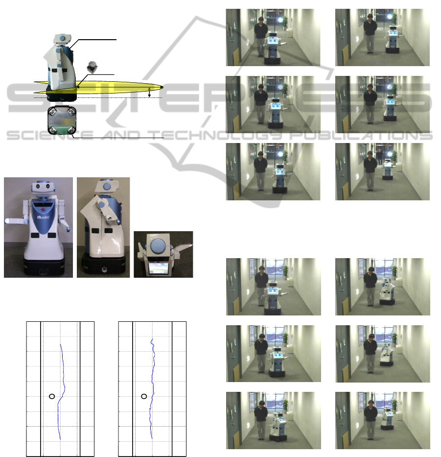
Figure 21: Laser sensor and an omni-directional platform
on an autonomous mobile robot.
(a) Front (b) Side (c) Top
Figure 22: Experimental situation.
(a) Method I (b) Method II
Figure 23: Trajectory of the robot.
4 EXPERIMENTAL RESULTS
To verify the performance of the proposed collision
avoidance method to static obstacles, an experiment
using the real robot were carried out. In order to
recognize the environment, as shown in Figure 21,
the robot has external sensors, such as a stereo
camera, laser range finder and ultrasonic sensors.
However, in this research the robot recognizes the
environment using only laser range finder.
(a) (d)
(b) (e)
(c) (f)
Figure 24: Experimental result to static human using fuzzy
potential method without PMF for rotational motion
(method I).
(a) (d)
(b) (e)
(c) (f)
Figure 25: Experimental result to static human using fuzzy
potential method with PMF for rotational motion (method
II).
LRF
4.0m
0.23m
+120°
‐120°
Omni Wheeled Platform
MKR-003
LRF
4.0m
0.23m
+120°
‐120°
Omni Wheeled Platform
MKR-003
-1.0
0.0
1.0
2.0
3.0
4.0
5.0
6.0
7.0
8.0
-2.0 -1.0 0.0 1.0 2.0
y-coordinate [m]
x-coordinate [m]
-1.0
0.0
1.0
2.0
3.0
4.0
5.0
6.0
7.0
8.0
-2.0 -1.0 0.0 1.0 2.
0
y-coordinate [m]
x-coordinate [m]
ICINCO 2011 - 8th International Conference on Informatics in Control, Automation and Robotics
12
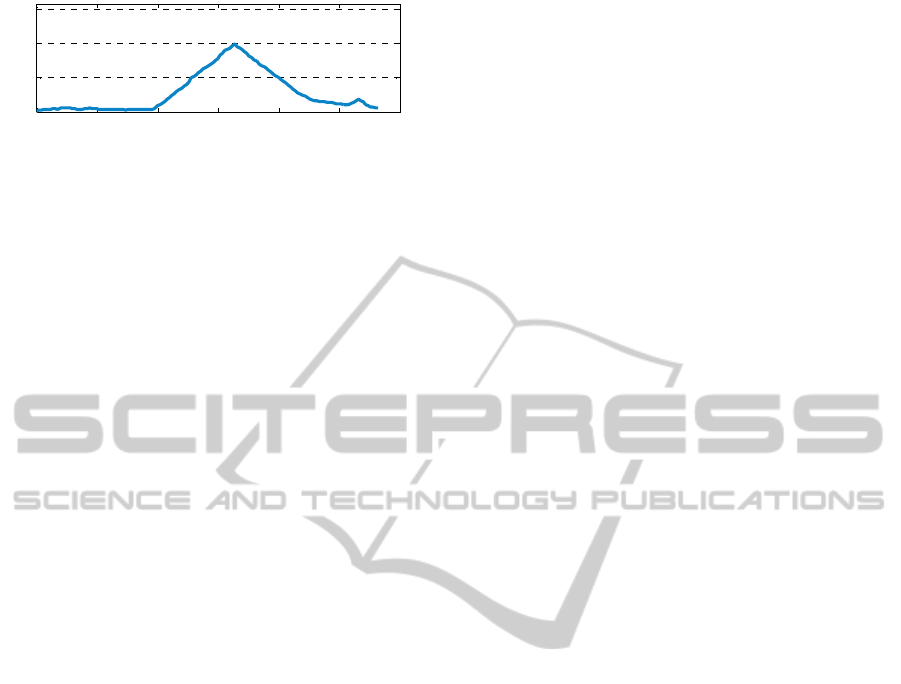
Figure 26: Time history of yaw angle of the robot.
The upper limit of the velocity of the robot was
0.5 m/s. The upper limit of the acceleration of the
robot was 1.0 m/s
2
. The arm position was set as
shown in Figure 22. Figures 23(a) and 24 showed
that the robot with method I can reach the goal
without colliding with the obstacle. However, the
position of the right arm comes close to the right-
side wall.
On the other hand, it was confirmed in Figures
23(b), 25 and 26 that the robot with the proposed
method (method II) changes the orientation angle of
the robot to keep the safe distance with the right-side
wall and can reach the goal point without colliding
with the obstacle.
5 CONCLUSIONS
In this paper, the real-time collision avoidance
method with simultaneous control of both
translational and rotational motion with
consideration of a robot width for an autonomous
mobile robot, which is horizontally long, has been
proposed. This method used an omni-directional
platform for the drive system and was based on the
fuzzy potential method. The novel design method of
potential membership function, which takes the
robot's size into consideration using the capsule case,
was introduced. With the proposed method, the wide
robot can decide the direction of translational motion
to avoid obstacles safely. In addition, by controlling
rotational motion in real time, the wide robot moves
while keeping a safe distance with surroundings in
narrow space. The effectiveness has been verified by
numerical simulations and experiments. It has been
shown that the proposed method performs
translational and rotational motion simultaneously
according to the situation.
REFERENCES
Kavraki, L., 1995. Computation of Configuration Space
Obstacles Using the Fast Fourier Transform,
IEEE
Trans. on Robotics and Automation
, Vol. 11, No. 3, pp.
408-413.
Wang, Y., Chirikjian, G. S., 2000. A New Potential Field
Method for Robot Path Planning,
Proc. IEEE Int. Conf.
on Robotics and Automation
, San Francisco, CA, pp.
977-982.
Ambrose, R. O., Savely, R. T., Goza, S. M., Strawser, P.,
Diftler, M. A., Spain, I., and Radford, N., 2004.
Mobile manipulation using NASA’s robonaut, Proc.
IEEE ICRA
, pp. 2104-2109.
Du, Z., Qu, D., Yu, F. and Xu, D, 2007. A Hybrid
Approach for Mobile Robot Path Planning in Dynamic
Environments,
Proc. IEEE Int. Conf. on Robotics and
Biomimetics
, pp.1058-1063.
Khatib, O., 1986. Real-time Obstacle Avoidance for
Manipulators and Mobile Robots, Int. J. of Robotics
Research
, Vol.5, No.1, pp.90-98.
Koren, Y., and Borenstein, J., 1991. Potential Field
Methods and Their Inherent Limitations for Mobile
Robot Navigation,
Proc. IEEE Int. Conf. on Robotics
and Automation
, pp.1398-1404.
Borenstein, J., Koren, Y. , 1989. Real-Time Obstacle
Avoidance for Fast Mobile Robots, IEEE Trans. on
Systems, Man, and Cybernetics
, Vol.19, No.5,
pp.1179-1187.
Borenstein, J., Koren, Y., 1991. The Vector Field
Histogram Fast Obstacle Avoidance for Mobile Robots,
IEEE Trans. on Robotics and Automation, Vol.7, No.3,
pp.278-288.
Lumelsky, V. J., Cheung, E. , 1993. Real Time Obstacle
Collistion Avoidance in Teleoperated Whole Sensitive
Robot Arm Manipulators, IEEE Trans. Systems, Man,
and Cybernetics
, Vol.23, No.1, pp.194-203.
Borenstein, J., Koren, Y., 1991. The Vector Field
Histogram Fast Obstacle Avoidance for Mobile Robots,
IEEE Trans. on Robotics and Automation, Vol.7, No.3,
pp.278-288.
Dieter, F., Wolfram, B., Sebastian, T., 1997. The Dynamic
Window Approach to Collision Avoidance,
IEEE
Robotics and Automation
, Vol. 4, No. 1, pp.1-23.
Tsuzaki, R., Yoshida, K., 2003. Motion Control Based on
Fuzzy Potential Method for Autonomous Mobile
Robot with Omnidirectional Vision”.
Journal of the
Robotics Society of Japan
, Vol.21, No.6, pp.656-662.
Takahashi, M., Suzuki, T., 2009. Multi Scale Moving
Control Method for Autonomous Omni-directional
Mobile Robot,
Proc. of the 6th Int. Conf. on
Informatics in Control, Automation and Robotics
.
0 5 10 15 20 25 30
0
1
2
3
Time [s]
Yaw angle [rad]
π
OBSTACLE AVOIDANCE WITH SIMULTANEOUS TRANSLATIONAL AND ROTATIONAL MOTION CONTROL
FOR AUTONOMOUS MOBILE ROBOT
13
