
BEYOND DESIGN PATTERNS
Improving Software Design with Pluggable Units
Fernando Barros
Departamento de Engenharia Inform
´
atica, Universidade de Coimbra, 3030 Coimbra, Portugal
Keywords:
Reusable software, Design patterns.
Abstract:
Design patterns provide solutions to recurrent problems and they have been extensively used in software
development. However, patterns favor a distinction based on small design differences leading to the creation
of a large number of solutions. Additionally, patterns are often hard to integrate making it difficult to develop
applications based in pattern composition. In this paper we exploit the ability of independent and pluggable
software units (PUs) to provide a unifying representation of design patterns. Preliminary results demonstrate
that patterns can effectively be represented by PUs using a reduced set of constructs. In particular we show
that patterns considered to belong to different categories are the same using a representation based on PUs.
This is the case of the Observer and Composite patterns, that are considered as belonging to the behavioral
and structural category, respectively.
1 INTRODUCTION
Design patterns have solved some limitations of
object-oriented programming (Gamma et al., 1995),
and they have been extensively used in application
development, making it easier to evolve and to main-
tain software. A large number of patterns have been
identifyed/created, and currently, pattern identifica-
tion, application and integration becomes a major bot-
tleneck in pattern use. Since patterns are not based
on a reduced set of constructs, the emphasis on small
differences can easily be used to create new patterns,
leading to increasing levels of complexity. In this pa-
per we consider independent and pluggable software
units (PUs) (Barros, 2005) as an alternative represen-
tation to design patterns. In particular, we develop
PU-based representations of the Observer and Com-
posite patterns and we demonstrate that these pat-
terns are effectively the same under the PU paradigm.
These results point the potential of PUs for represen-
ting apparently unrelated abstractions. We demon-
strate the ability of PUs to develop complex appli-
cations by modeling a lunar lander vehicle, a system
that have been extensively used to show software ar-
chitectures capabilities (Taylor et al., 2010). The lu-
nar lander system requires the integration of several
design patterns, a feature difficult to achieve using
object-oriented programming (Cacho et al., 2006).
We demonstrate that under PUs, patterns can be seam-
lessly integrated and we describe a solution devel-
oped reusing existing PUs. Examples are provided
in JUSE , a Java/Groovy realization of PUs.
2 REPRESENTING DESIGN
PATTERNS WITH PLUGGABLE
UNITS
Pluggable Units (PUs) enable the development of
software based on independent units (Barros, 2005).
PUs extend the object paradigm by employing the
concept of output interface to enable software inde-
pendence while keeping request-reply communica-
tion, supported by the mostly used programming lan-
guages. PUs define two type of entities: basic PUs
responsible for method invocation, and network PUs
that define message passing and PU composition. In
this section we provide a representation of the Ob-
server and Composite design patterns (Gamma et al.,
1995), that are shown to be the same under PUs.
2.1 Observer
The Observer design pattern, and its related sibling
Model-View-Controller (MVC), are probably the
123
Barros F..
BEYOND DESIGN PATTERNS - Improving Software Design with Pluggable Units.
DOI: 10.5220/0003466001230128
In Proceedings of the 6th International Conference on Software and Database Technologies (ICSOFT-2011), pages 123-128
ISBN: 978-989-8425-77-5
Copyright
c
2011 SCITEPRESS (Science and Technology Publications, Lda.)
most well known entries of the patterns catalog.
These patterns have been widely used for developing
applications and frameworks, most notably GUI
frameworks like, for example, Java/Swing and
JavaBeans. The Observer pattern has contributed to a
new branch of programming termed by Event-Based
Programming that uses the Observer publish/sub-
scribe communication protocol to define the basic
message passing infrastructure (Fiege et al., 2002).
To show how PUs can trivially describe the Observer
pattern we use a simple bank account application that
can update account balance and compute the average
balance. Additionally, the current account balance is
displayed in two different widgets. The bank account
is defined in Listing 1 using the JUSE language, a
Java/Groovy realization of PUs.
1class
Account
extends
Connecton {
2private float
balance = 0f;
3public
GateCollection inGates() {
4return super
.inGates().add("deposit");
5
}
6public
GateCollection outGates() {
7return super
.outGates().add("balance");
8
}
9public void
deposit(
float
value) {
10
balance += value;
11out
.balance(balance);
12
}
13
}
Listing 1:
Account
PU.
This PU has input gate
deposit
to make deposits.
Other gates could be considered but are omitted for
simplicity. Whenever the balance is changed its cur-
rent value is sent through output gate
balance
, Line
11. The concept of output gate is a major change to
object-oriented programming enabling software inde-
pendence as we show next. Each costumer is rep-
resented by the
Customer
PU, a network PU repre-
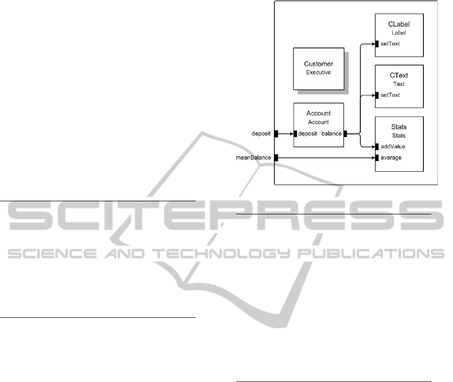
sented in Figure 1 and defined in Listing 2.
The
Customer
network is composed by 5 PUs. A
special PU termed by
Executive
keeps the network
topology. The
Account
PU output gate
balance
is
linked to
CLabel
,
CText
and to
Stats
PU. The first
PUs are widgets that display account balance. These
widgets wrap Java/Swing classes into PUs, enabling
the development of GUI applications with pluggable
software units. The
Stats
PU defines the input gate
addValue
to receive a new balance, keeping account
statistics. The average account balance can be ob-
tained through the network input gate meanBalance.
Figure 1:
Customer
topology.
1class
Customer
extends
Executive {
2public
GateCollection netInGates() {
3return
super
.netInGates().add("deposit").add("meanBalance");
4
}
5public void
topology() {
6
addS(Account, "Account");
7
addS(Stats, "Stats");
8
addS(CText, "Text");
9
addS(CLabel, "Label");
10
linkS("Network", "deposit", "Account", "deposit");
11
linkS("Network", "meanBalance", "Stats", "average");
12
linkS("Account", "balance", "Stats", "add");
13
linkS("Account", "balance", "Text", "setText", "{[
float
x] -> [x.toString()]}");
14
linkS("Account", "balance", "Label", "setText",
"{[
float
x] -> [x.toString()]}");
15
}
16
}
Listing 2:
Observer
PU.
Since, the Account interfaces are not compatible
with other PUs, filters are created to make the adap-
tation. Lines 13-14 convert the
float
balance into a
String
required by the widgets. This conversion can
actually be considered the Adapter pattern (Gamma
et al., 1995), that becomes materialized in a filter.
When the balance is updated its current value is sent
through output gate
balance
and broadcasted to all
linked PUs that for this particular topology display
the current balance and compute balance average. Us-
ing PUs, an Observer becomes simply any gate that
has several links attached to it, making this pattern
a mere topological feature. No particular constructs
were developed to represent the Observer that uses
the general purpose operators defined for linking PUs.
Since all PUs are homogenous, any PU can act as
both Subject and Observer of any other PU, making
the Observer pattern irrelevant. In fact, the partition-
ing of applications into patterns become meaningless
using PUs that can seamlessly combine design pat-
ICSOFT 2011 - 6th International Conference on Software and Data Technologies
124
terns. Patterns become indistinguishable, being im-
plicitly represented in the topology. In the next sec-
tion we show that the Composite pattern, a structural
SDP, is the very same as the Observer pattern, a be-
haviorial SDP, providing further evidence of our con-
jectures.
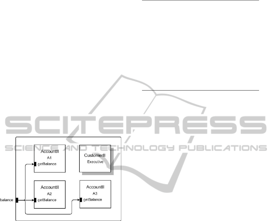
2.2 Composite
The Composite pattern enables an insightful compar-
ison with the Observer pattern described in Section
2.1. For describing the Composite we consider the
CustomerII
network of Figure 2 with three accounts
A1
,
A2
and
A3
. Each
AccountII
PU can compute its
balance and we are interested in the aggregated bal-
ance of a customer. This problem can be represented
with the Composite pattern that handles the iteration
to obtain the balance of each account and then com-
putes the sum.
Figure 2:
CustomerII
topology.
The topology of Figure 2 is defined by Listing 3.
At first glance, taking only into account the graphical
representation, this topology is equal to the Observer
topology of Figure 1. In reality, we face the same
topology. However, there is a subtle difference not
highlighted by the graphical definition: in this exam-
ple we take care of the results obtained by the input
gate
balance
and we sum the returned values from
each account to compute the total balance. This sum
is computed by the filter function associated with gate
balance
and defined in Lines 4-6.
In this representation using PUs, the Observer and
Composite patterns are not just similar, they are ef-
fectively the same. The differences are only based on
the particular use we made of parameters and return
values. In the Observer case, we expect no return va-
lues from the observers and thus gate functions can
be omitted. In the Composite case we are usually in-
terested in the return values, being common that no
parameter is provided.
1class
CustomerII
extends
Executive {
2public
GateCollection netInGates() {
3return super
.netInGates().add("balance",
4
"{ArrayList list -> //computes the sum using
"inject"
5return
list.inject(0){
float
x,
float
y -> x +
y}
6
}";
7
}
8public void
topology() {
9
addS(AccountII, "A1");
10
addS(AccountII, "A2");
11
addS(AccountII, "A3");
12
linkS("Network", "balance", "A1", "getBalance");
13
linkS("Network", "balance", "A2", "getBalance");
14
linkS("Network", "balance", "A3", "getBalance");
15
}
Listing 3:
CustomerII
PU.
Gate
balance
makes the combination of these behav-
iors employing the same constructs. We consider that
trying to introduce any distinction between these two
patterns under a software topology is mostly arbitrary
and useless. Actually, some languages, like Pascal,
have introduced the distinction between functions and
procedures to represent return and non-return value
calls. However, this distinction is nowadays consid-
ered awkward and major mainstream languages do
not usually support this classification. We have made
no assumption about the nature of the
AccountII
PU, that can be either a basic or a network PU, en-
abling the trivial definition of composite observers.
The nested definition of observers/composites is en-
abled by the recursive definition of PU networks, a
built-in feature, as opposed to a specific characteristic
of a given design pattern.
3 PATTERN INTEGRATION
A major problem with design patterns is that they
make it difficult to establish a solution to a problem
as a combination several patterns (Cacho et al., 2006).
To demonstrate PU ability to represent more complex
systems we model a vehicle that is intended to land
in the moon at safe velocity. This system has been
extensively used for describing software architectures
(Taylor et al., 2010). However, it has been described
with simple dynamics valid only for small time in-
tervals (Taylor et al., 2010), and not adequate to re-
present the complete trajectory of a lander vehicle.
A more realistic behavior can be found in (Cellier,
1991). Our representation is able to describe a soft-
ware application with a complex GUI interface, while
keeping detailed dynamics that take into account ac-
celeration and fuel variation. The PU representation
of the application is depicted in Figure 3, where ren-
dering information (panels and frames), is omitted for
BEYOND DESIGN PATTERNS - Improving Software Design with Pluggable Units
125

simplification. Vehicle is described by the following
ordinary differential equations (ODES):
Fuel
′
= −k · T hrust
Y
′′
=
T hrust
M
Total
− G
M
Moon
(Radius
Moon
+Y )
2
where the lander total mass is given by:
M
Total
= Fuel + M
Lander
Vehicle dynamics are modeled by the integrators
Y
,
VY
and
Fuel
, that numerically solve this set of
ODEs. The lander thrust is set by the slider
Thrust
that can be directly controlled by users. Several plot-
charts depict, thrust, fuel, velocity and position. Va-
lues are sampled by the
Sampler
PU and sent to
the plot charts
Y-Plot
,
VY-PLot
,
Thrust-Plot
and
Fuel-Plot
. Zero-cross detectors monitor vehicle
fuel and position. If the fuel becomes zero the lan-
der starts a free fall. When lander position reaches
zero the simulation stops.
Variable plots are depicted in Figure 4, for a sys-
tem in the following initial conditions: vehicle mass =
38.0 kg; fuel = 1000.0 kg; position = 60000.0 m and
velocity = -2000.0 m/s.
The representation of this system would require
several design patterns. The Composite pattern can
be discovered, for example, in the connections be-
tween the
Sampler
PU and the
Integrator
s. The
Sampler
output gate
sample
is used to retrieve the
current values from the integrators and from the verti-
cal slider (
VSlider
). These values are then combined
into one array and sent through the
Sampler
output
gate
value
. A different value is chosen from this
array by the filters located in the links between gate
value
and each input gate
add
of the plotters. This
pattern identification effort, however, seems to bring
no benefit, being essentially useless. Composite can
also be found in the
VY
integrator that samples
Y
,
Fuel
and
Thrust
PUs. These values are then combined to
compute lander acceleration.
Each output gate in figure 3 can also be identi-
fied with an Observer, since an arbitrary number of
links can be connected from a single output gate. In
particular,
Sampler
output gate
value
resembles the
Observer pattern, since this gate is connected to the
input gate
add
of different
Plotter
s. Although, as
mentioned before,
Sampler
output value is actually
filtered at each like, no return values is issued by
the plotters and the gate behaves as an observer. A
more conventional observer behavior can trivially be
achieved at this gate by adding different widgets/plot-
ers for representing the same value.
The kind of graphical representation used in the
lunar lander system is commonly accomplished with
the Model-View-Controller pattern (Freeman and
Freeman, 2004). We emphasize that, although all PUs
are independent and reusable in arbitrary contexts, no
clear separation of the lunar lander into MVC compo-
nents can meaningfully be made in a representation
based on PUs. Actually, PU-based design tends only
to impose two types of constraints: the development
of applications form existing PUs and the develop-
ment of new PUs in order to maximize their proba-
bility of reuse. These features promote the systematic
reuse of software.
The presented results point to the irrelevance of
patterns, in opposition to other paradigms, like soft-
ware architectures, where they are considered to be
useful in software design (Shaw and Garlan, 1996;
Taylor et al., 2010). Our results have been confirmed
by the development of several applications using PUs.
Actually, given the widget library and the library of
active PUs that include integrators, detectors and sam-
plers, the lunar landing system was developed with
essentially no code. The created code being essen-
tially declarative defining the topology in a manner
described in Listings 2 and 3. Patterns, on the con-
trary can hardly support this productive form of reuse
achieved with PUs.
We have limited our discussion to the Composite
and Observer design patterns, since these patterns are
commonly classified as belonging to different cate-
gories. However, under a PU representation they are
actually the same. Other patterns can also be triv-
ially represented as specific topologies, requiring no
special operators to be used. This is the case, for
example, for the Chain of Responsibility design pat-
tern as shown in (Barros, 2005). This pattern can
also be considered present in the lunar landing sys-
tem. Looking at the relationship between integrators,
we observe that the
Fuel
samples from
Thrust
,
VY
samples from
Fuel
, and
Y
samples from
VY
, making
it a pipeline topology that resembles the Chain of Re-
sponsibility. Actually, since
VY
also samples from
Y
,
a feedback loop is established, and the topology de-
parts form the simple pipeline. Contrarily to design
patterns, PUs can be placed into arbitrary topologies
without any constraint imposed by their internal de-
sign, becoming, thus, very flexible and enabling a su-
perior support for software reuse.
4 RELATED WORK
The principles of hierarchical decomposition and in-
dependence have been considered as key constructs
for handling complex problems in many fields. One
of the first formal descriptions of independent decom-
position has been made in the area of General Systems
ICSOFT 2011 - 6th International Conference on Software and Data Technologies
126
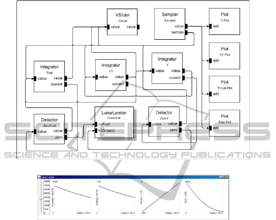
Figure 3:
LunarLander
topology.
Figure 4: Lunar lander state variables plot.
Theory (Wymore, 1967). An earlier use of indepen-
dence in software was made in (Kahn, 1974), where
a synchronous programming language was defined.
The main limitations of general systems formalisms
and is related to the underlaying communication that
is not compliant with the request-reply protocol used
by most programming languages (Barros, 1997). The
same drawbacks apply to coordination languages and
process calculus (Arbab, 2004; Hoare, 1985; Milner
et al., 1989), that do not support request-reply com-
munication, becoming difficult to use.
To bridge the gap between specifications and im-
plementations, hierarchical and modular constructs
have been introduced into existing programming lan-
guages (Aldrich et al., 2002; Molkentin, 2007; Tay-
lor et al., 2010). However, none of theses approaches
provide the general support to independent software
as provided by PUs. Limitations include the lack of
filters and input/output functions making these ap-
proaches not compliant with our definition of inde-
pendence. Observer and Composite pattern unifica-
tion is not possible in ArchJava (Aldrich et al., 2002)
since it cannot handle sets of simultaneous return va-
lues.
Attempts to provide a common representation for
design patterns have shown that most patterns could
not be componentizable (Arnout, 2004). Patterns re-
quire their re-implementation in particular contexts,
preventing the definition of patterns libraries and the
effective reuse of software. In fact, this limitation
seems to be inherent to the object-oriented technology
that is unable to support systematic software reuse.
A representation of Composite using Aspect-
Oriented Programming AOP can be found in (Hanne-
mann and Kiczales, 2002). However, this representa-
tion follows closely the OOP design pattern (Gamma
et al., 1995), introducing a specific aspect for descri-
bing the Composite. This solution, does not achieve
an independent design and it is longer and harder to
understand when compared with the corresponding
solutions based on PUs. The representation of Ob-
server in AOP has been described (Hannemann and
BEYOND DESIGN PATTERNS - Improving Software Design with Pluggable Units
127

Kiczales, 2002; Pawlak et al., 2006). This solution,
however, closely follows the original definition, and
likewise Composite, it introduces aspects to repre-
sent the observer pattern, requiring a partitioning into
subjects an observers. The AOP representation did
not achieve unified representation of patterns like we
point in this work. The representation of Observer us-
ing software architectures was also proposed (Oder-
sky and Zenger, 2005; Sreedhar, 2002). These ap-
proaches, however, leads to a complex description of
the pattern that is quite similar to the original one.
Event-based programming has been used as the
basis for some software architectures (Luckham and
Vera, 1995; Taylor et al., 2010). However, EBP is
based on the Observer pattern, one star in the pattern
galaxy, being obviously unable to provide a unified
pattern representation.
5 CONCLUSIONS
Design patterns provide solutions to overcome some
limitations of object-oriented programming. Patterns
however, are not based on simple and sound princi-
ples, leading to an explosion of their number. This
was the case of Observer and Composite patterns that
albeit considered very different under OOP, are ex-
actly the same under the software topology paradigm.
Patterns provide no meaningful insight on how appli-
cations can be partitioned and organized becoming an
irrelevant construct for developing software topolo-
gies. Our current work has shown that most of the pat-
terns defined in (Gamma et al., 1995) are actually spe-
cific topologies with small differences between them.
Future research is required to extend our results to a
larger number of patterns.
ACKNOWLEDGEMENTS
This work was partially supported by the Portuguese
Foundation for Science and Technology under project
PTDC/EIA-EIA/100752/2008.
REFERENCES
Aldrich, J., Chambers, C., and Notkin, D. (2002). ArchJava:
Connecting software architecture to implementation.
In International Conference on Software Engineering,
pages 187–197.
Arbab, F. (2004). Reo: A channel-based coordination
model for component composition. Mathematical
Structures in Computer Science, 14(3):329–366.
Arnout, K. (2004). From Patterns to Components. PhD
thesis, ETH Z
¨
urich.
Barros, F. (1997). Modeling formalisms for dynamic struc-
ture systems. ACM Transactions on Modeling and
Computer Simulation, 7(12):505–515.
Barros, F. (2005). System and method for programming
using independent and reusable software units. US
Patent 6851104 B1.
Cacho, N., Sant’Anna, C., Figueiredo, E., Garcia, A.,
Batista, T., and Lucena, C. (2006). Composing De-
sign Patterns: A Scalability Study of Aspect-Oriented
Programming.
Cellier, F. (1991). Continuous System Modeling. Springer-
Verlag.
Fiege, L., M
¨
uhl, G., and Gartner, F. (2002). Modular event-
based systems. The Knowledge Engineering Journal,
17(4):359–388.
Freeman, E. and Freeman, E. (2004). Head First Design
Patterns. O’Reilly.
Gamma, E., Helm, R., Johnson, R., and Vlissides, J. (1995).
Design Patterns. Addison-Wesley.
Hannemann, J. and Kiczales, G. (2002). Design Pattern
Implementation in Java and AspectJ. OOPSLA.
Hoare, C. (1985). Communicating Sequential Processes.
Prentice Hall.
Kahn, G. (1974). The Semantics of a Simple Language for
Parallel Programming.
Luckham, D. and Vera, J. (1995). An event-based architec-
ture definition language. IEEE Transactions on Soft-
ware Engineering, 21(9):717–734.
Milner, R., Parrow, J., and Walker, D. (1989). A Calculus of
Mobile Processes, Part I/II. Number ECS-LFCS-89-
85/86.
Molkentin, D. (2007). The Book of Qt 4: The Art of Building
Qt Applications. Open Source Press.
Odersky, M. and Zenger, M. (2005). Scalable component
abstractions. In Object-Oriented Programming Sys-
tems Languages and Applications, pages 41–57.
Pawlak, R., Seinturier, L., and Retaill
´
e, J.-P. (2006). Foun-
dations of AOP for J2EE Development. A-Press.
Shaw, M. and Garlan, D. (1996). Software Architecture.
Prentice Hall.
Sreedhar, V. (2002). Mixin’up Components. International
Conference on Software Engineering.
Taylor, R., Medvidovic, N., and Dashofy, E. (2010). Soft-
ware Architecture. Wiley.
Wymore, A. (1967). A Mathematical Theory of Systems
Engineering. Krieger.
ICSOFT 2011 - 6th International Conference on Software and Data Technologies
128
