
MODEL-DRIVEN TESTING
Transformations from Test Models to Test Code
Beatriz Pérez Lamancha, Pedro Reales Mateo, Macario Polo
ALARCOS research group, Castilla-La Mancha University, Ciudad Real, Spain
Danilo Caivano
Dipartamento di Informatica, Universitá degli Studi, Bari, Italy
Keywords: Model-driven testing, Model-based testing, UML testing profile, Transformation, Model to text
transformation, MOFScript, xUnit, JUnit.
Abstract: In MDE, software products are built with successive transformations of models at different abstraction
levels, which in the end are translated into executable code for the specific platform where the system will
be deployed and executed. As testing is one of the essential activities in software development, researchers
have proposed several techniques to deal with testing in model-based contexts. In previous works, we
described a framework to automatically derive UML Testing-Profile test cases from UML 2.0 design
models. These transformations are made with the QVT language which, like UML 2.0 and UML-TP, is an
OMG standard. Now, we have extended the framework for deriving the source code of the test cases from
those in the UML Testing Profile. This transformation, which can be applied to obtain test cases in a variety
of programming languages, is implemented with MOFScript, which is also an OMG standard. Thus, this
paper almost closes our cycle of testing automation in MDE environments, always within the limits of OMG
standards. Moreover, thanks to this standardization, the development of new tools is not required.
1 INTRODUCTION
Currently, new technologies, new tools and new
development paradigms exist that help to reduce
software development time. Increasingly, software
development models are being used to a greater or
lesser degree. These models can be used for
requirements elicitation, to achieve a common
understanding with stakeholders or to build and
share the architecture solution. Model-Driven
Engineering (MDE) considers models for software
development, maintenance and evolution through
model transformation (Mens and Van Corp, 2006).
Testing must support software development,
reducing testing time but ensuring the quality of the
product generated. Model-based testing (MBT)
provides techniques for the automatic generation of
test cases using models extracted from software
artefacts (Dalal et al., 1999). Several approaches
exist for model-based testing (Dias Neto et al., 2007,
Prasanna et al., 2005). Nonetheless, adoption of
model-based testing by the industry remains low and
signs of the anticipated research breakthrough are
weak (Bertolino, 2007). In this work, we use the
term model-driven testing to refer to a model-based
testing approach that follows the MDE paradigm,
i.e., using model transformations.
In previous works (Perez Lamancha et al., 2010,
Pérez Lamancha et al., 2009a), we defined an
automated model-driven testing framework. This
framework uses two types of transformations, the
first of which is model-to model-transformation to
generate test models from design models. This
transformation takes UML 2.0 models as input and
through QVT, produces UML Testing Profile
models (this can be consulted in (Pérez Lamancha et
al., 2009b)).
The second type of transformations is test model
to test code transformation, which is the main
contribution of this paper.
Figure 1 describes the transformation from test
model to test code. The transformation is developed
using the MofScript tool (2011b), which implements
the OMG´s MOF model-to-text transformation
121
Pérez Lamancha B., Reales Mateo P., Polo M. and Caivano D..
MODEL-DRIVEN TESTING - Transformations from Test Models to Test Code.
DOI: 10.5220/0003466201210130
In Proceedings of the 6th International Conference on Evaluation of Novel Approaches to Software Engineering (ENASE-2011), pages 121-130
ISBN: 978-989-8425-57-7
Copyright
c
2011 SCITEPRESS (Science and Technology Publications, Lda.)
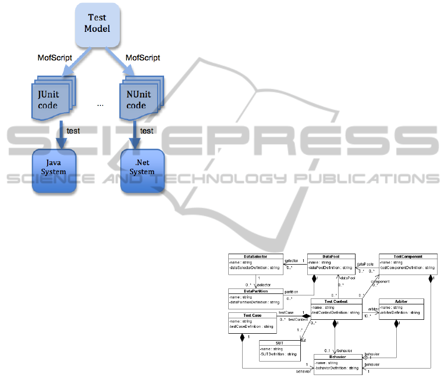
(OMG, 2008). In this work, the transformation
generates JUnit code (2011a), which makes it
possible to automate the coding of Java test cases
and their management. It is also possible to generate
other testing code, for example, NUnit (2011c) to
test .Net systems.
Figure 1: Test model to test code transformations.
Once the test code is obtained by the
transformation, it can be compiled and executed to
test the system under test (SUT) and to obtain the
test case verdict, i.e., whether it fails or passes.
Section 2 presents the metamodels and standards
used in this paper. Section 3 describes the approach
for model-driven testing and presents the automated
testing framework. Section 4 summarizes the model
to model transformations definded in the framework.
Section 5 describes transformations from test models
to test code using MofScript in detail. Section 6
summarizes the works related to our approach.
Finally, Section 7 presents conclusions and future
work.
2 METAMODELS AND
STANDARDS
One of the central parts of MDE is model
transformation, defined as the process of converting
one model to another model of the same system
(Miller and Mukerji, 2003). Even with the source
code, programs are expressed in a programming
language; if we make the correspondence between a
grammar and a metamodel explicit, programs may
be converted into equivalent MDA-models (Bezivin,
2005). A transformation requires: (i) source and
target models, (ii) source and target metamodels and
(iii) the definition of the transformation (Miller and
Mukerji, 2003). In this work the metamodel used is
the UML Testing Profile.
UML 2.0 Testing Profile (UML-TP) (OMG,
2005) defines a language for designing, visualizing,
specifying, analyzing, constructing and documenting
the artefacts of test systems. It extends UML 2.0
with specific concepts for testing, grouping them in
test architecture, test data, test behaviour and test
time.
Figure 2 shows an excerpt of the UML-TP
metamodel. The test architecture in UML-TP is the
set of concepts to specify the structural aspects of a
test situation. It includes the TestContext, which
contains the test cases (as operations) and whose
composite structure defines the test configuration.
The test behaviour specifies the actions and
evaluations necessary to evaluate the test objective,
which describes what should be tested. The
TestCase specifies one case to test the system,
including what to test it with, the required input,
result and initial conditions. It is a complete
technical specification of how a set of
TestComponents interacts with a System Under Test
(SUT) to realize a TestObjective and returns a
Verdict value (OMG, 2005).
Figure 2: UML-TP metamodel.
We use two transformations: for model to model
transformation (M2M) we selected the OMG’s
Queries, Views and Transformations (QVT)
standard (OMG, 2007). The QVT standard describes
three languages for transformations: Relations,
Operational and Core. Of these, we used the
Relations language, where each relation specifies
how an element (or set of elements) from the source
models is transformed into an element (or set of
elements) of the target model. The Operational
language can be used to implement one or more
Relations from a Relations specification when it is
ENASE 2011 - 6th International Conference on Evaluation of Novel Software Approaches to Software Engineering
122

difficult to provide a purely declarative specification
of how a Relation is to be populated. QVT Core is a
low-level language into which the others can be
translated (OMG, 2007). One of the advantages of
the QVT standardization is its adoption by tool
vendors, which also entails the possibility of
interchanging models across different platforms.
For model to code transformation (M2C), we
use the MOFScript tool (2011b), an implementation
of OMG’s MOF Model to Text transformation
language (MOF2Text) (OMG, 2008). Each
transformation defined with this language is
composed of a texttransformation element. A
texttransformation is the main element that
transforms a model into text. These models are
specified as inputs in the transformation. Also, a
texttransformation can import other previously
defined transformations.
A texttransformation is composed of rules. A
rule is basically the same as a function. Each rule
performs a sequence of operations or calls to other
rules in order to analyze the input models and
generate the desired text. Each rule has a context
type, which is a type of input metamodel. This
represents the type of elements to which the rule can
be applied. Also, a rule can have a return element,
which can be reused in other rules and input
parameters to perform the operations defined in the
rule. Both the return and the input parameter have a
type of input metamodel or basic type, which is
defined by MOFScript language.
A texttransformation element can also have an
entry point rule. This is a special type of rule called
main. This rule is the first rule to be executed when
the transformation is executed and has the
responsibility for executing the rest of the
transformation rules.
The M2C transformation in our case generates
xUnit code. xUnit is a family of frameworks, which
enable the automated testing of different elements
(units) of software. Such frameworks are based on a
design by Kent Beck, originally implemented for
Smalltalk as SUnit (Beck, 1999). Gamma and Beck
ported SUnit to Java, creating JUnit (2011a). From
there, the framework was also ported to other
languages, as NUnit for .NET.
3 MODEL DRIVEN TESTING
APPROACH
Our proposal for model driven testing automatize the
generation of test cases from design models using
model transformations. We have defined an
automated framework, based on Dai’s idea (Dai,
2004). Figure 3 shows the models involved in the
framework, which is divided vertically into System
models (left) and Testing models (right). For
System models, the framework follow the MDA
(Miller and Mukerji, 2003) levels. MDA defines
three viewpoints of a system (Harmon, 2004):
(i) the Computation Independent Model (CIM),
which focuses on the context and
requirements of the system without
considering its structure or processing;
(ii) the Platform Independent Model (PIM), which
focuses on the operational capabilities of a
system outside the context of a specific
platform; and
(iii) the Platform Specific Model (PSM), which
includes details relating to the system for a
specific platform.
The philosophy of MDA can be applied to test
modeling. As Figure 3 shows, the same abstraction
levels (PIM, PSM) can be applied to test models.
The Test levels defined are (Dai, 2004):
(i) platform independent test model (PIT),
(ii) platform specific test model (PST) and
(iii) executable test code.
Furthermore, with the adequate transformations,
test models can directly proceed from system
designs. The arrows in Figure 3 represent
transformations between models.
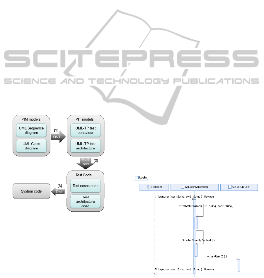
Figure 3: Model-driven testing approach.
The main characteristics of the automated
framework for model-driven testing that we have
defined and implemented are (Perez Lamancha et
al., 2010):
Standardized. The framework is based on
Object Management Group (OMG) standards,
where possible. The standards used are UML,
UML Testing Profile as metamodels, and
Query/View/Transformation (QVT) and
MOF2Text as standardized transformation
languages.
MODEL-DRIVEN TESTING - Transformations from Test Models to Test Code
123
Model-driven Test Case Scenario Generation.
The framework generates the test cases at the
functional testing level (which can be extended
to other testing levels); the test case scenarios are
automatically generated from design models and
evolve with the product until the test code
generation. Design models represent the system
behaviour using UML sequence diagrams.
Framework Implementation using Existing
Tools. No tools have been developed to support
the framework: existing market tools that
conform to the standards can be used. The
requisite is that the modelling tool can be
integrated with the tools that produce the
transformations.
Figure 4 shows the UML diagrams used in the
framework. For each functionality represented as a
sequence diagram at PIM level, the test case is
automatically generated using QVT (arrow 1). The
transformation generates the test case behaviour as
another sequence diagram and a class diagram
representing the test architecture. Both models
conform to the UML Testing Profile (UML-TP).
Earlier works (Pérez Lamancha et al., 2009b, Perez
Lamancha et al., 2010), presented this
transformation, summarized in Section 4.
Figure 4: Metamodels involved in the testing framework.
In this paper, the transformation from test models
to test code is described. This transformation
corresponds to arrow (2) in Figure 3 and Figure 4.
With this transformation the entire cycle is closed,
and the framework is completed. As result, an
executable test code is generated from a test model,
which in turn proceeds from the design model.
For the transformation in arrow (2), test models
represented using UML-TP are the input, and the
test code is the output. This test code can be written
according to several testing frameworks (for
example JUnit, the unit testing framework for Java).
This transformation is done using MOF Model-to-
Text (OMG, 2008). Once the test code is obtained, it
can be compiled and possibly executed. With this
executable test code, the system can be tested (arrow
3 in Figure 4).
4 TEST MODEL GENERATION
This section explains how the test cases can be
derived from sequence diagrams at functional test
level, corresponding to arrow 2 in Figure 4. A UML
Sequence diagram is an Interaction diagram, focused
on the message interchange between lifelines. A
sequence diagram describes sequences of events.
Events are points on the lifeline, such as the sending
of a message or the reception of a message (Baker et
al., 2007) . A sequence diagram can be used to show
the system behaviour for a use case scenario in a
design model as well as to show the behaviour of a
test case in a test model.
Figure 5 shows the main scenario of the “Login”
use case, where a user gives his/her user name and
password and the system checks whether both
parameters are valid; if they are, the system creates a
new session for that user. To generate the test case
for a sequence diagram, from a functional testing
point of view, the system must be considered as a
black box and the stimulus from the actor to the
system must be simulated and vice versa. Using the
UML-TP, actors are represented with
TestComponents, whilst the System is represented
with the SUT.
Figure 5: UML sequence diagram for “Login”.
ENASE 2011 - 6th International Conference on Evaluation of Novel Software Approaches to Software Engineering
124
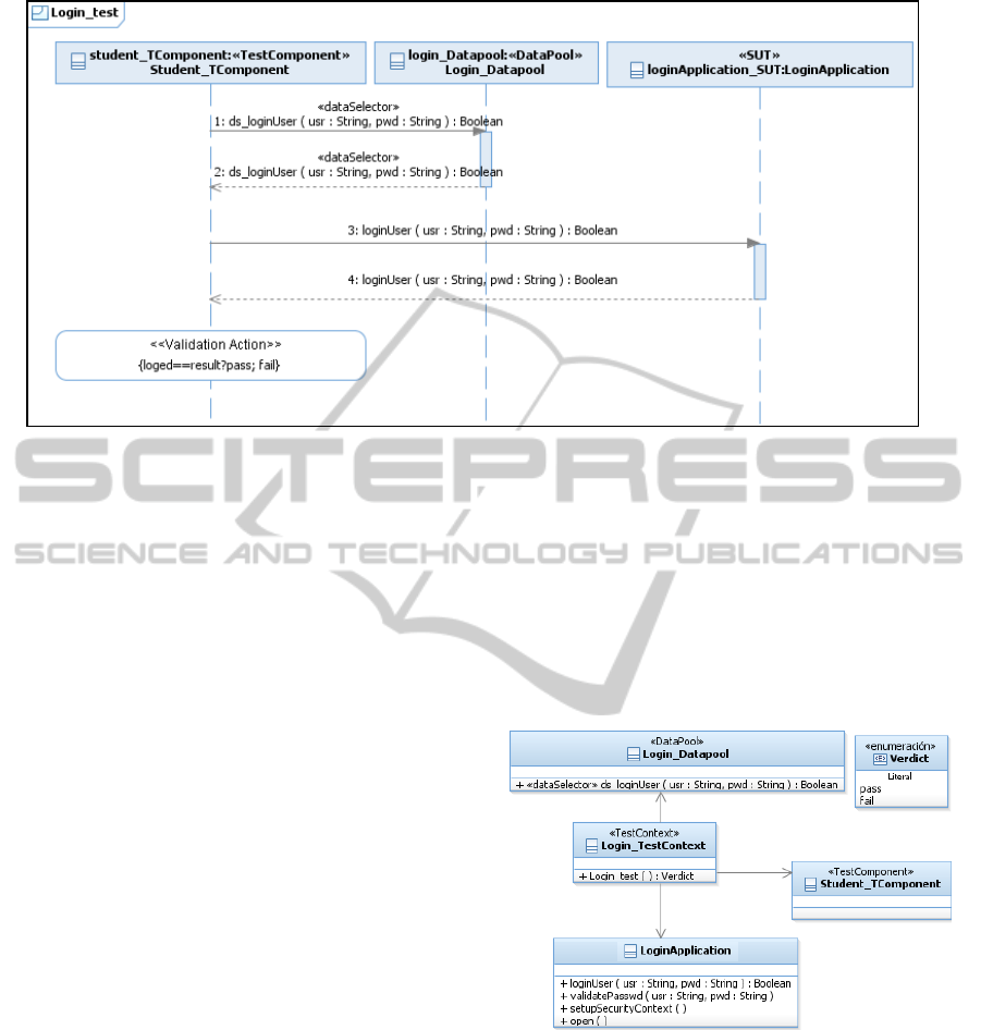
Figure 6: Test case automated generated using QVT transformation from Login sequence diagram.
In our proposal, each message between the actor
and the SUT must be tested. For this, the following
steps in the test case behaviour are generated:
• Obtaining the test data: To execute the test
case, the required test data is stored in the
DataPool. The TestComponent asks for the
test data using the DataSelector operation in
the DataPool.
• Executing the test case in the SUT: The
TestComponent simulates the actor and
stimulates the SUT. The TestComponent calls
the SUT functionality to be tested: i.e.,
TestComponent calls the message to test in the
SUT.
• Obtaining the test case verdict: The
TestComponent is responsible for checking
whether the value returned for the SUT is
correct, and uses the Validation Action for
that.
Figure 6 shows the test case generated to test the
functionality of Figure 5. The TestComponent
(Student_TComponent) simulates the Student actor
in Figure 5. It obtains the test data necessary from
the DataPool, executes the operations of the system,
and finally uses a ValidationAction to check the
correct running of the system. The first message in
Figure 6 calls the loginUser(uid,psw):Boolean. To
test this, first, the arguments are taken from the
DataPool using a DataSelector for each argument;
the DataPool retrieves the user (uid), password
(pwd) and the expected result (result). The
TestComponent executes the loginUser method in
the SUT (message labelled 3 in Figure 6), and the
return from the SUT is the real result (logged).
Finally, the Validation Action is responsible for
the test case verdict: the test case passes if the
expected result is equal to the actual result;
otherwise, it fails.
Figure 7 shows the resulting test architecture
derived for this example, which conforms to the
UML-TP metamodel. Since the UML-TP is a UML
Profile, the classes defined in the test architecture
are stereotyped.
Figure 7: Test architecture generated.
The main concepts generated are:
• Login_TestContext: Stereotyped as
<<TestContext>>, includes the operation
Login_test for executing the test.
• Login_DataPool: Stereotyped as
<<DataPool>> contains the test data. Operations
in this class are stereotyped as <<DataSelector>>
and will be used in the tests to obtain the test
data. Includes the operation DataSelector
ds_loginUser.
MODEL-DRIVEN TESTING - Transformations from Test Models to Test Code
125
• Student_TComponent: Stereotyped as
<<testComponent>> is responsible for initiating
the test case and interchanging events with the
SUT to test the functionality.
More information about the semantic of the
transformations from design to test models and
about how QVT transformations were developed can
be consulted in (Pérez Lamancha et al., 2009b).
5 TRANSFORMATIONS FROM
MODELS TO CODE
This section presents the main contribution of the
paper: transformations from test models to test code,
which corresponds to the arrow labelled 2 in Figure
5.
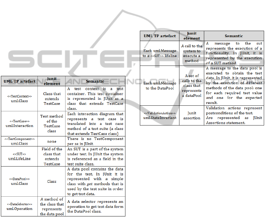
Table 1: Transformation rules semantic for test archi-
tecture (adopted from UML-TP).
Our approach applies the idea of MDA
development to testing. MDA separates business
complexity from the implementation details, by
defining several software models at different
abstraction levels (Mellor et al., 2004, Kleppe et al.,
2003).
Once the test cases and the test architecture are
obtained, the next step is to obtain the test code to
test the system. Table 1 shows how the test model is
transformed to test code.
We use JUnit test code to exemplify the
transformation. The transformation takes UML-TP
models as input and generates JUnit Code as output.
Table 1 shows the semantic of the transformation
rules to generate the test code. The first column
shows the UML-TP artefact, the second shows the
JUnit element generated and the third describes the
semantic of the transformation. UML-TP
specification describes the transformations to JUnit
for the test architecture.
However, transformation rules for behavioural
test cases are defined by us, taking into account the
characteristics of the sequence diagrams generated
(see
Table 2).
Table 2: Transformation rules semantic for test behaviour.
5.1 MOFScript Transformations
Two MofScript transformations have been
implemented to perform the transformations in
Table 1 and
Table 2. These MofScript
transformations are TextContextMapping and
DataPoolMapping.
TestContextMapping transformation is
responsible for generating the JUnit code that
contains the test cases, and the body of the test
cases. This transformation has a set of rules that can
be split into two:
1) rules to create the architecture (the test suite
class and the test case methods) and
2) rules to create the body of the test cases (in
the next section).
The first kind of rule analyzes the packages, classes
and sequence diagrams that represent test cases and
create a specialization of TestSuite class for each
class stereotyped as <<TestContext>>. Parameters
and methods in the model are in turn translated into
Java parameters and methods (excepting the
operations which are realized by sequence diagrams
stereotyped as <<TestCases>>).
ENASE 2011 - 6th International Conference on Evaluation of Novel Software Approaches to Software Engineering
126
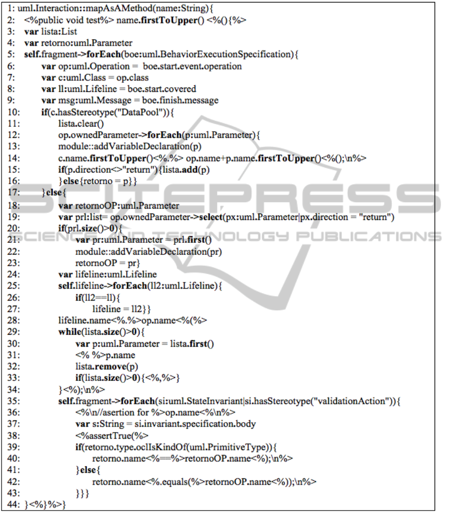
Table 3: MofScript rule: MapAsAMethod to transform an iteration into a method.
The second kind of rule creates the test cases. They
analyze the sequence diagrams stereotyped as
<<TestCase>>. Each time an operation of a test
context is carried out, a new method is created in a
test suite (previously generated from the text
context). The method name starts with the word
“test” and it has not returned value to the
parameters. Then, the rules generate the body of the
method analyzing the sequence of messages inside
the sequence diagram. The transformations
performed by this kind of rule are described in
details in the following section.
The DataPoolMapping transformation is
responsible for creating the Java classes that
MODEL-DRIVEN TESTING - Transformations from Test Models to Test Code
127
represent DataPools for the tests. This
transformation is only composed of rules to create
the architecture, because the body of the methods
simply returns a value.
5.2 An Example of Mofscrip Rule:
Uml:Interaction::mapAsAMethod
This section presents an example of a transformation
rule using MofScritp. Rule
uml:Interaction::mapAsAMethod of the
transformation TextContextMapping is shown in
Table 3.
This rule transforms a UML Interaction
stereotyped as “TestCase” into a JUnit test method
that belongs to the resulting test suite class.
Basically, the rule creates the header of the method
and searches sequences of three elements (as shown
in
Table 3:
i) a call to the DataPool,
ii) a call to the SUT and
iii) a state invariant, in order to create the
body of the method.
Statement 2 creates the method header. Then
statement 5 creates a loop that goes all over the
messages, searching the messages for the DataPool,
SUT and the stateinvariant. When a message to the
DataPool is found, it searches for the remaining calls
described above.
At this point the execution of two iterations is
required. The first iteration creates the calls to the
DataPool and stores the required information for the
next iteration. Statements 11-16 translate the
message to the DataPool into a set of calls to the
DataPool, one for each parameter passed by the
reference. This division is required because in UML
a method can have many parameters by reference
but in Java the parameters are passed by value and
there is only a return parameter. Another possibility
would be to create a method that returns a vector in
order to contain all the parameters by reference, but
for simplicity’s sake, we chose to create several
calls. To create these calls, the auxiliary function
addVariableDeclaration is used. This function
creates the declaration of the variable that will
contain the value retuned by the DataPool.
The second iteration creates a call to the SUT.
Statements 18-34 deal with the translation of the
message to the SUT into a call to the SUT. These
statements can be split into two parts. The first part
is composed of statements 18-23. These statements
check when the call to the SUT has a return value,
and in that case create a variable declaration using
the addVariableDeclaration function that will
contain the value returned by the SUT. Statements
24-34 compose the second part. These statements
create the call to the SUT using the variables that
contain the data obtained from the DataPool.
At the end of the second iteration, an assertion
with the information stored in the state invariant
element is generated, which is just after the message
element that represents the call to the SUT.
Statements 35-43 deal with translating the state
invariant elements into JUnit assertions. The
statements simply create an assertion and compare
the expected result obtained from the DataPool with
the result obtained from the SUT.
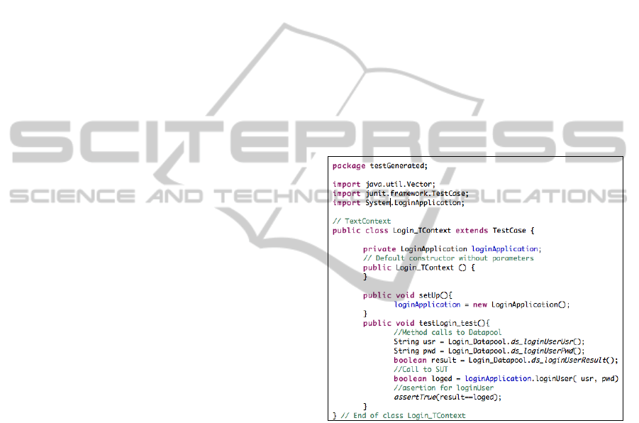
5.3 JUnit Code Generated
Once MofScript transformations are executed, the
JUnit test case is obtained. Figure 8 shows the JUnit
test code generated.
Figure 8: JUnit test code generated.
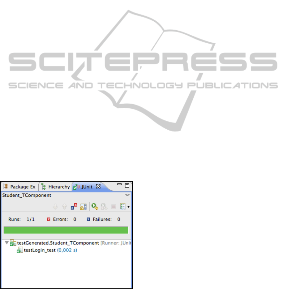
This test code could be compiled and executed.
After this compilation, JUnit shows its execution
results (Figure 9).
5.4 Model-driven Testing Framework
Implementation
The implementation of the framework requires the
selection of a modelling tool from those on the
market, as well as the identification of the tools to
perform transformations between the models and
from model to code. Our selected tool was IBM
Rational Software Architect (IRSA). This tool
graphically represents the sequence diagrams and
exports them to UML2 through XMI.
ENASE 2011 - 6th International Conference on Evaluation of Novel Software Approaches to Software Engineering
128
The Eclipse IDE makes it possible to use
modelling tools in an integrated way, using
extensions in the form of plug-ins. Eclipse plug-ins,
which are used to perform modelling tasks, exist.
The Eclipse Modelling Framework (EMF) plugin
allows the development of metamodels and models:
from a model specification described in XMI, it
provides tools and runtime support to produce a set
of Java classes for the model, along with a set of
adapter classes that enable viewing and command-
based editing of the model. UML2 is an EMF-based
implementation of the UML 2.0 OMG metamodel
for the Eclipse platform. UML2 Tools is a Graphical
Modelling Framework editor for manipulating UML
models.
The transformation between models (arrow 1 in
Figure 4) uses QVT language, which requires the
tool that implements the standard. medini QVT is a
plugin for eclipse that implements OMG's QVT
Relations specification in a QVT engine. We used it
to develop and execute the QVT transformations
(Pérez Lamancha et al., 2009b).
The model-to-text transformations have been
defined with MofScript language, and it thus
requires a tool that supports this language. The
MOFScript tool (2011b) is a plugin for Eclipse that
makes it possible to develop transformations with
the language MofScript. This tool has been used to
develop and perform the transformations presented
in this paper. It has a code editor to define the
transformations, which brings out the reserved word
of the language and has autocompletion features.
This tool also has a MofScript checker and an
execution engine to check the syntax of the defined
transformations and execute them.
Figure 9: JUnit test case execution.
6 RELATED WORKS
Many proposals for model-based testing exist (Dias
Neto et al., 2007, Prasanna et al., 2005), but few of
them focus on automated test model generation
using model transformations.
Dai (Dai, 2004) describes a series of ideas and
concepts to derive UML-TP models from UML
models, which are the basis for a future model-based
testing methodology. Test models can be
transformed either directly to test code or to a
platform specific test design model (PST). After
each transformation step, the test design model can
be refined and enriched with specific test properties.
However, to the best of our knowledge, this
interesting proposal has no practical implementation
for any tool.
Baker et al. (Baker et al., 2007) define test
models using UML-TP. Transformations are done
manually instead of using a transformation language.
Naslavsky et al. (Naslavsky et al., 2007) use
model transformation traceability techniques to
create relationships among model-based testing
artefacts during the test generation process. They
adapt a model-based control flow model, which they
use to generate test cases from sequence diagrams.
They adapt a test hierarchy model and use it to
describe a hierarchy of test support creation and
persistence of relationships among these models.
Although they use a sequence diagram (as does this
proposal) to derive the test cases, they do not use it
to describe test case behaviour.
Javed et al. (Javed et al., 2007) generate unit test
cases based on sequence diagrams. The sequence
diagram is automatically transformed into a unit test
case model, using a prototype tool based on the
Tefkat transformation tool and MOFScript for model
transformation. This work is closed to ours, but they
don´t uses the UML-TP. We generate the unit test
case in two steps and they in only one. We think that
use a intermediate model using UML-TP as PIT is
more appropiate to follow a MDE approach.
7 CONCLUSIONS
We have presented our framework for automated
model-based testing using standardized metamodels
such as UML and UML-TP. In this paper the
complete transformations cycle defined in the
framework is implemented, obtaining executable test
cases procedures in JUnit code.
To obtain complete test cases we also need to
define the way in that test data are generated: at this
MODEL-DRIVEN TESTING - Transformations from Test Models to Test Code
129

moment, both the test data and the expected result
(which are required for the test oracle) are manually
stored in the datapool. Our ongoing work uses UML
State Machines to define the test oracle.
Future work includes implementing MOFScript
transformations to generate NUnit test cases, the
application of the entire framework in an industrial
project and, as we have pointed out, to take
advantage of state machine annotations to
automatically include the oracle in the test cases.
ACKNOWLEDGEMENTS
This research was financed by the projects:
DIMITRI (Ministerio de Ciencia e Innovación, grant
TRA2009_0131) and the project PEGASO/MAGO
(TIN2009-13718-C02-01) from MICINN and
FEDER. Pérez has a doctoral grant from JCCM,
Orden de 13-11-2008. Reales has a doctoral grant
from the “Ministerio de Educación”, Real Decreto
63/2006.
REFERENCES
(2011a) JUnit. http://www.junit.org/. Access: May 2011.
(2011b) MofScript. http://www.eclipse.org/gmt/
mofscript/. Access: May 2011.
(2011c) NUnit. http://www.nunit.org/. Access: May 2011.
Baker, P., Dai, Z., Grabowski, J., Schieferdecker, I.,
Haugen, O. & Williams, C. (2007) Model-Driven
Testing: Using the UML Testing Profile, Springer.
Beck, K. (1999) Kent Beck's guide to better Smalltalk: a
sorted collection, Cambridge University Press.
Bertolino, A. (2007) Software Testing Research:
Achievements, Challenges, Dreams. Internation
Conference on Software Engineering. IEEE Computer
Society.
Bezivin, J. (2005) On the unification power of models.
Software and Systems Modeling, 4, 171-188.
Dai, Z. (2004) Model-Driven Testing with UML 2.0.
Second European Workshop on Model Driven
Architecture (MDA) with an emphasis on
Methodologies and Transformations. Canterbury,
England.
Dalal, S., Jain, A., Karunanithi, N., Leaton, J., Lott, C.,
Patton, G. & Horowitz, B. (1999) Model-based testing
in practice. ICSE. IEEE Computer Society.
Dias Neto, A. C., Subramanyan, R., Vieira, M. &
Travassos, G. H. (2007) A Survey on Model-based
Testing Approaches: A Systematic Review. 1st ACM
international workshop on Empirical assessment of
software engineering languages and technologies.
ACM.
Harmon, P. (2004) The OMG's Model Driven Architecture
and BPM. Newsletter of Business Process Trends.
Javed, A., Strooper, P. & Watson, G. (2007) Automated
generation of test cases using model-driven
architecture. 2nd International Workshop on
Automation of Software Test. AST'07.
Kleppe, A., Warmer, J. & Bast, W. (2003) MDA
Explained; The Model Driven Architecture: Practice
and Promise, Addison-Wesley.
Mellor, S., Scott, K., Uhl, A. & Weise, D. (2004) MDA
Distilled: Principles of Model-Driven Architecture,
Addison Wesley.
Mens, T. & Van Corp, P. (2006) A Taxonomy of Model
Transformation. Electronic Notes in Theoretical
Computer Sciences, 152, 125-142.
Miller, J. & Mukerji, J. (2003) MDA Guide Version 1.0.
1. Object Management Group.
Naslavsky, L., Ziv, H. & Richardson, D. J. (2007)
Towards traceability of model-based testing artifacts.
3rd international workshop on Advances in model-
based testing. London, United Kingdom, ACM.
Omg (2005) UML testing profile Version 1.0. IN Group,
O. M. (Ed.).
Omg (2007) MOF Query/View/Transformation
Specification.
Omg (2008) MOF Model to Text Transformation
Language. Version 1.0 ed., OMG.
Perez Lamancha, B., Polo, M. & Piattini, M. (2010) AN
AUTOMATED MODEL-DRIVEN TESTING
FRAMEWORK for Model-Driven Development and
Software Product Lines. Fifth International
Conference on Evaluation of Novel Approaches to
Software Engineering. Athens, Greece, SciTePress.
Pérez Lamancha, B., Polo Usaola, M. & García Rodriguez
De Guzmán, I. (2009a) Model-Driven Testing in
Software Product Lines. 25th International IEEE
Conference on Software Maintenance (ICSM09).
Edmonton, Canadá, IEEE.
Pérez Lamancha, B., Reales Mateo, P., García Rodriguez
De Guzmán, I., Polo Usaola, M. & Piattini, M.
(2009b) Automated Model-based Testing using the
UML Testing Profile and QVT. IN Acm (Ed.) 6th
International Workshop on Model-Driven
Engineering, Verification and Validation
(MODEVVA'09). Denver, Colorado.
Prasanna, M., Sivanandam, S., Venkatesan, R. &
Sundarrajan, R. (2005) A survey on automatic test
case generation. Academic Open Internet Journal, 15,
1-5.
ENASE 2011 - 6th International Conference on Evaluation of Novel Software Approaches to Software Engineering
130
