
INTER-MODEL CONSISTENCY BETWEEN UML STATE MACHINE
AND SEQUENCE MODELS
Yoshiyuki Shinkawa
Department of Media Informatics, Ryukoku University, 1-5 Seta Oe-cho Yokotani, Otsu, Shiga, Japan
Keywords:
UML, Model Consistency, Colored Petri Nets.
Abstract:
UML state machine diagram and sequence diagram represent a system or software from contrastive two view-
points, namely part and whole. If these diagrams depict the same system, they must be consistent with each
other. However, UML does not provide us with an appropriate way to evaluate the consistency between the
models drawn by these different diagrams. This paper reveals the interrelationships between state machine
and sequence diagrams based on the ordering of method invocations, which determine the behavior of them.
Focusing on these relationships, two criteria are introduced to evaluate the consistency. The evaluation is per-
formed using Coloured Petri Nets (CPN) so that both diagrams are expressed and compared in the same form,
with the same syntax and semantics.
1 INTRODUCTION
UML state machine diagram and sequence diagram
are two of the most used diagrams in modeling the be-
havioral aspects of a system to be developed. While
the former mainly expresses the behavior of individ-
ual object participating in the system, the latter deals
with the behavior of the system in the form of inter-
actions between these objects. These two kinds of di-
agrams can be regarded to have a part-whole relation-
ship, and therefore they must be consistent with each
other.
However, if these diagrams are used indepen-
dently to model the objects and the system, it is diffi-
cult to maintain consistency between the models writ-
ten using these different diagrams
1
. If there are in-
consistencies between the above models, the resultant
system would include various problems, e.g. unex-
pected malfunctions.
One of the reasons for this difficulty is that no ap-
propriate ways are provided by UML to evaluate the
consistency between these models (Egyed, 2006), and
it seems to be caused by expressive diversity and in-
sufficient formalization of UML.
Various efforts have been made to formalize UML
1
In this paper, we call a model written using a specific
UML diagram as diagram-name + models, e.g. a sequence
model means a model written by UML sequence diagram.
for more rigorous specification and verification us-
ing diverse formal techniques, which include process
algebra (Fischer et al., 2001), formal specification
languages like Z (Amalio and Polack, 2003), VDM,
(Lausdahl et al., 2009) or B (Snook and Butler, 2008),
model checking (Knapp and Wuttke, 2006), and Petri-
Nets (Garrido and Gea, 2002). These formal tech-
niques examine the structure, functionality, and be-
havior of the models written by UML diagrams pre-
cisely, and express the model semantics in their own
syntaxes.
On the other hand, much fewer efforts have been
made for inter-model relationships written by differ-
ent UML diagrams, such as the relationship between
UML state-machine models and sequence models. In
order to evaluate the inter-model consistency between
different UML models, we have to formalize not only
the internal structure of each model, but also the in-
terrelationships between them.
This paper presents a formal and systematic
way to evaluate inter-model consistency between the
above two kinds of UML models using Colored Petri
Nets (CPN) as a formalization technique. The paper
is organized as follows. In section 2, interrelation-
ships between the models are examined and revealed.
Section 3 discusses the transformation of UML state
machine and sequence models into CPN models. Sec-
tion 4 presents how the transformed CPN models are
evaluated to determine whether they are consistent.
135
Shinkawa Y..
INTER-MODEL CONSISTENCY BETWEEN UML STATE MACHINE AND SEQUENCE MODELS.
DOI: 10.5220/0003474001350142
In Proceedings of the 6th International Conference on Software and Database Technologies (ICSOFT-2011), pages 135-142
ISBN: 978-989-8425-77-5
Copyright
c
2011 SCITEPRESS (Science and Technology Publications, Lda.)

2 INTERRELATIONSHIPS
BETWEEN THE MODELS
State machine and sequence models represent the be-
havior of a system from different viewpoints, based
on different model components. Therefore, we first
have to identify the commonality between these mod-
els. We focus on the states of objects for this com-
monality.
In object oriented approaches, each object can
have states which are externally observable. At high
abstraction levels, these states are recognized as the
observable transitory properties of an object such as
appearances, dimensions, or activities currently per-
formed by the object. On the other hand, at more con-
crete levels, they are expressed as a value or a set of
values of the variable or variables in the object.
In order to make the discussion precise, we adopt
the latter interpretation of the states, and define them
as follows.
1. Let Ω be an object, including the variables
X = {x
1
,··· ,x
n
} for its attributes, each of which
is associated with the value space X
i
= dom(x
i
).
2. For a sub-domain S ⊆ X
1
× · · · × X
n
, if the two
tuples of values
(a
1
,··· ,a
n
) ∈ S ⊆ X
1
× ···× X
n
(b
1
,··· ,b
n
) 6∈ S ⊆ X
1
× ···× X
n
are externally distinguishable, and the distinction
is meaningful from an application viewpoint, S
forms a state S of the Ω.
3. The collection of such sub-domains defines a set
of the states Σ = {S
1
,··· ,S
m
}, where S
i
is a sub-
domain that is recognized as a state.
This definition relates a state of an object with a sub-
domain of the variables in the object. Such a sub-
domain can be defined by a logic formula with pred-
icates. For example, if the temperature and humidity
of an object Room are represented by the variables x
and y respectively, and the state uncomfortable is de-
fined by the sub-domain
S = {(x, y)|x > 30, y > 60} ∪ { (x, y)|x ≤ 10}
the state is represented as a logic formula
P(x,y) =
G(x,30) ∧ G(y, 60)
∨ ¬G(x,10)
where G(u,v) is the predicate, meaning u is greater
than v. Even though there could be many different
forms of a logic formula, there can be a unique prenex
conjunction normal form (PCNF), that is, the formula
written as a string of quantifiers (∀ and ∃), followed
by a conjunction of clauses.
Assuming each state in a state machine model rep-
resents such a state, a state transition
S
i
ε [ γ ] / α
−−−−−→ S
j
means the update of the variables by the action α,
when the guard γ holds. The symbol ε represents an
event triggering the transition. The above action α is
implemented as a method of the object, if the state
variables are fully encapsulated. Therefore, in such a
situation, a series of state transitions correspond to a
series of method invocations, each of which updates
the values of the state variables.
On the other hand, a sequence model represents
the interactions between lifelines in the form of mes-
sage passing. These lifelines can represent various
concepts and entities, e.g. classes, objects, actors, or-
ganizations, or other participants to the system to be
modeled.
In order to identify the interrelationships between
state machine and sequence models, both models
must have the common components, therefore we re-
gard the lifelines as objects. In this interpretation, a
receiving event occurrence represents a method invo-
cation in a sequence model.
One of the ways to express the behavior of a se-
quence model is to show the series of messages ex-
changed between lifelines. Regarding the lifelines
as objects, this series also represents the series of
method invocations. This series can be defined for
the whole system or for a specific object, by extract-
ing the method invocations along the lifeline.
From the discussion so far, two series of method
invocations can be obtained for the same object, one
from a state machine model, and the other from a
sequence model. Therefore, by refining these mod-
els appropriately to make these two series consist of
the same set of the methods, they can be a measure
to define the interrelationships between the two mod-
els. One of the differences between these two series
is that the sequence model might include the mes-
sages not affecting the states of the object. A typi-
cal such a message is an inquiry message, which only
returns some information without updating the state
variables.
Taking the above difference into account, the
inter-model consistency between state machine and
sequence models from a method invocation viewpoint
is defined as follows.
1. Let A = a
1
a
2
···a
n
and B = b
1
b
2
···b
m
be the ob-
tained series of method invocations from state ma-
chine and sequence models respectively for the
same object.
2. Remove such methods from B that do not occur in
A , and let C = c
1
c
2
···c
p
be the remainder series
of B .
ICSOFT 2011 - 6th International Conference on Software and Data Technologies
136

3. C must occur in A as a partial series of method in-
vocations, since C represents the series of method
invocations updating the states of the belonging
object.
The above series are not so easily obtained be-
cause of complicated structures of state machine and
sequence models. In order to identify and examine
these series automatically, we use Colored Petri Nets
(CPN) and CPN Tools (Jensen and Kristensen, 2009).
Before discussing the usage of them, we introduce an-
other consistency criterion based on the states of ob-
jects.
Unlike state machine models, sequence models
are scarcely founded on the concept of states. How-
ever, there are several points in a sequence model
where we can recognize the states. One is a state in-
variant located on a lifeline, and the other is a guard
that is occurred in some combined fragments like alt
and loop.
While the guards only control the sequence of
message passing, and might be true or false, the state
invariants represent the conditions that have to be sat-
isfied at specific points in the sequence model, and
must be true. Therefore, state invariants are eligible
to evaluate the consistency.
Since the method invocation sequence in a se-
quence model is matched with that of the correspond-
ing state machine model, the states in the state ma-
chine model can be injected into the sequence model,
so that we can identify the states at the receiving event
occurrences where the corresponded messages arrive
at.
By this injection, each lifeline is partitioned into
zones associated with the states as shown in Figure 1.
As stated above, the states can be expressed in
the form of logical formulae with state variables, and
therefore we can assign these logical formulae to the
above zones. On the other hand, state invariants are
the assertions on the states, either object or system
states, and can be expressed in the form of logical for-
mulae.
Since each state invariant is located at a particular
point on a lifeline, it belongs to one of these zones as-
sociated with a logical formulae. Therefore, the state
invariant must not conflict with the logical formula of
the zone it belongs. Let the state invariantbe S(~u), and
the logical formula of the associated zone be P(~x),
P(~u) → P(~x)
must hold, where~u and~x represent the state variables.
These state injection and state invariant consis-
tency are also implemented by CPN.
3 MODEL COMMONIZATION
WITH CPN
Colored Petri Nets (CPNs) are one of the extensions
of regular Petri nets, which can express the structure,
behavior, and functionality simultaneously for vari-
ous systems. CPN is formally defined as a nine-tuple
CPN=(P, T, A, Σ, V, C, G, E, I) , where
P : a finite set of places.
T : a finite set of transitions.
(a transition represents an event)
A : a finite set of arcs P∩ T = P∩ A = T ∩ A =
/
0.
Σ : a finite set of non-empty color sets.
(a color represents a data type)
V : a finite set of typed variables.
C : a color function P → Σ.
G : a guard function T → expression.
(a guard controls the execution of a transition)
E : an arc expression function A → expression.
I : an initialization function : P → closed expression.
3.1 Transforming State Machine
Models into CPN
State machine models and CPN models show similar
properties, since both originated from finite automata.
The structural relationships between these two mod-
els are as follows.
1. Each state in a state machine model corresponds
to a place in a CPN model. The color associated
with the place is composed of the types of the state
variables.
2. A state transition corresponds to a transition put
between two places that reflect the source and des-
tination states of the state machine
For a label on the state transition, which is de-
noted as ”event[guard]/action”, the event and guard
are transformed into a guard function of the associ-
ated CPN transition, while the action is transformed
into the outgoing arc function that updates the token
value.
Based on the above structural correspondences, it
is required to build a behaviorally equivalent CPN
model to a given state machine model, in order to
commonize state machine and sequence models.
Unlike simple finite automata, UML state ma-
chine models can include complicated control struc-
tures and functionality, and they must be embedded
in the CPN models. These can be expressed in the
form of CPN as follows.
INTER-MODEL CONSISTENCY BETWEEN UML STATE MACHINE AND SEQUENCE MODELS
137
L1
a1
b1
c1
d1
a3
S0
State Machine Model
for the Object L1
Sequence Model Including
the Object L1 as a Lifeline
S1
S3
e1[g1]/a1
S2
e2[g2]/a2 e3[g3]/a3
Injected State
S0
S1
S3
Figure 1: State Injection into Sequence Model.
[Initial State]
An initial state is expressed in CPN as a place with
initial marking, and with no incoming arcs.
[Final State]
A final state is expressed as a place with no outgo-
ing arcs.
[Composite State]
A composite state includes another state machine
model inside, and expressed as a substitution transi-
tion in a CPN model, since this state itself can be re-
garded as a process or behavior.
[Submachine State]
A submachine state is an inserted state ma-
chine, and simply expressed using a hierarchical CPN
model.
[Entry Point]
An entry point is an alternative initial state, and
expressed in the same way as an initial state in
CPN. The initial marking of the CPN model controls
whether it becomes initial state.
[Exit Point]
An exit point is an alternative final state, and ex-
pressed in the same way as a final state. If entry or an
exit point is a submachine state, they are expressed as
a port-socket pair in CPN.
[Fork and Join Pseudo State]
A fork pseudo state initiates a parallel state tran-
sitions, whereas a join pseudo state merges them into
a single one. These pseudo states can be expressed as
splitting and merging transitions with multiple places
in CPN.
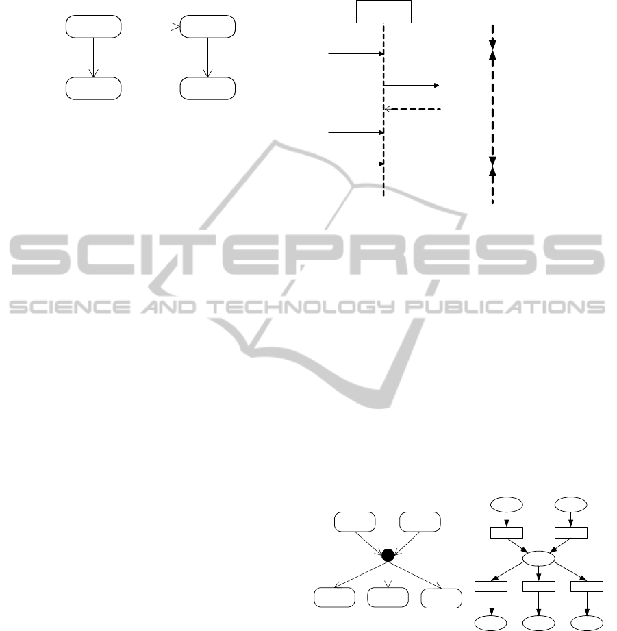
[Choice and Junction Pseudo States]
These pseudo states express control branches.
While the former realizes a dynamic branch, and
only one state transition is allowed, the latter real-
izes a static branch, and multiple state transitions
are possible. A choice pseudo state is simply im-
plemented by CPN using competing transitions with
guards. On the other hand, a junction pseudo state
is rather tricky, which is implemented using a inter-
mediate place and arc functions that provide empty
tokens if the guards fail. Figure 2 shows the junction
pseudo state with two incoming and three outgoing
state transitions, which is transformed into the CPN
model with the intermediate place “P”. The arc func-
tion “a
i
(i = 3,4,5)” are the CPN/ML functions
if g
i
then x else empty
where g
i
is the guard for the transition “Ti” and x is
the variable for the token.
S1 S2
S3 S4
S5
P1 P2
T1 T2
P
T3 T4 T5
P3 P4 P5
a3 a4 a5
[g3]
[g4]
[g5]
[g3] [g4] [g5]
Figure 2: Junction Pseudo State.
[Shallow and Deep History Pseudo States]
These pseudo states provide restart capability for
composite states. In CPN models, a substitution tran-
sition that is equivalent to the composite state must
also be restartable. This restart mechanism is realized
by appending three places, each of which represents
exit, checkpoint, and re-entry respectively, along with
an escape transition for each place that represents the
state.
ICSOFT 2011 - 6th International Conference on Software and Data Technologies
138

Shallow and deep are distinguished from each
other whether the above mechanism is nested or not.
3.2 Transforming Sequence Models into
CPN
There are two possible implementations of sequence
models by CPN.
One is a structure based implementation, which
assigns a place for each lifeline, and assigns a transi-
tion with an incoming arc to it for each incoming mes-
sage to the lifeline. We can easily transform a given
sequence model into CPN model using these simple
rules, however the resultant CPN model is not com-
patible with state machine models, since no concepts
of states are included.
The other is a state based implementation, which
takes the states of objects into account. As discussed
in Section 2, an injected state is defined for each
incoming message to a lifeline, of which operation
name occurs as an action name in the state machine
model for the object that the life line represents.
Therefore, a CPN model consisting of the places
for these injected states, and of the incoming arc with
a transition to the above each place, reflects this im-
plementation. Such a CPN model can basically be
transformed in the same way as state machines. How-
ever, sequence models could form more complicated
structure than state machine models using combined
fragments. The treatment of these combined frag-
ments is as follows (Shinkawa, 2006).
[Alternative and Option Fragments]
An alternative and option fragments, designated
by alt and opt tag, represent case and if - then struc-
tures respectively, and implemented by CPN using as
many transitions as the number of regions in the frag-
ment. Each transition is assigned a guard equivalent
to the guard of corresponded region.
[Loop Fragment]
A loop fragment, designated by loop tag, repre-
sents an iterative process, and is implemented using
two conflicting transitions for iteration and exit re-
spectively.
[Parallel Fragment]
A parallel fragment, designated by par tag, rep-
resents concurrent message passing between the life-
lines, and is interpreted as concurrent state transitions
in the state based implementation. This fragment is
expressed in CPN using a transition splitting one in-
coming arc into multiple outgoing arcs.
[Break Fragment]
A break fragment, designated by break tag, is used
to terminate the message passing in the outer frag-
ment, to which the break fragment belongs. Since
the fragment is controlled by a guard, it can be im-
plemented as a transition with the equivalent guard,
which puts a token into the place outside the fragment.
[Critical Fragment]
A critical fragment, designated by critical tag,
represents a message passing process that must be
performed exclusively, and usually used within a par-
allel fragment. This fragment is expressed in CPN us-
ing a place with a lock token. The locking mechanism
works as follows.
1. The first transition in the fragment gets the lock
in the above place, and the transition immediately
after the fragment return the lock.
2. Each transition that conflicts with the critical frag-
ment refers to this place, that is, bidirectional arcs
are drawn between the transition and the place.
[Weak Sequencing Fragment]
A weak sequencing fragment, designated by seq
tag, defines the ordering of messages as follows
(OMG, 2010).
1. The ordering of OccurrenceSpecifications within
each of the operands are maintained in the result.
2. OccurrenceSpecifications on different lifelines
from different operands may come in any order.
3. OccurrenceSpecifications on the same lifeline
from different operands are ordered such that
an OccurrenceSpecification of the first operand
comes before that of the second operand.
This fragment reduces to a par fragment if all the
operands include disjunct sets of lifelines interacting
together. Therefore, when tranforming it into CPN,
we first regard it as par fragment, then add the order-
ing restrictions to it. The detailed implementation is
as follows.
1. Build the CPN model for the seq fragment as par
fragment.
2. Derive all the ordering constraints ( ˆm
i, j
≺ ˆm
i+1,k
)
between (i)th and (i + 1)th operands or regions
P
i
and P
i+1
, where ˆm
i, j
and ˆm
i+1,k
represent the
receiving event occurrences for the message m
i, j
and m
i+1,k
in the operand P
i
and P
i+1
respectively.
3. Draw an additional arc between P ( ˆm
i, j
) to
T ( ˆm
i+1,k
), and modify the incoming arc function
of the P ( ˆm
i, j
) so that an extra token for the tran-
sition T ( ˆm
i+1,k
) is provided. In addition, modify
the guard of T ( ˆm
i+1,k
) for this extra token. P ( ˆm)
and T ( ˆm) represent the place and transition asso-
ciated with the receiving event occurrence ˆm.
For example, in Figure 3, the order of the re-
ceiving event occurrences, which are denoted by the
names of messages, must satisfy m
1
≺ m
2
and m
3
≺
INTER-MODEL CONSISTENCY BETWEEN UML STATE MACHINE AND SEQUENCE MODELS
139
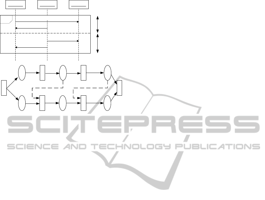
Object 1 Object 2
seq
Object 3
m1
m2
m3
m4
m1
m2
m3
m4
Operand 1
Operand 2
Figure 3: Weak Sequencing Fragment.
m
4
, and these constraints can be embedded into the
CPN model for par fragment using the additional arcs
shown by the dashed arrows. In addition, the place m
1
and m
2
must include the additional tokens for this se-
quence control, which can be implemented by the arc
functions toward them.
[Other Combined Fragments]
There are other supplementary combined frag-
ments like strict, assertion, ignore, consider, and
negation defined in a UML sequence model, however
they do not affect the essential behavior of the model,
and therefore we do not take them into account.
By applying the above process to a sequence
model, we can obtain a behaviorally equivalent CPN
model from the method invocation viewpoint. In ad-
dition, a CPN model for a specific lifeline or an object
can be obtained by extracting the places representing
the receiving event occurrences for the object, with
the incoming arcs. To make the complete CPN model
from these elements, a dummy initial place and tran-
sitions are added with the appropriate arcs.
4 EVALUATING THE
CONSISTENCY
For discussing the inter-model consistency between
models, we posit the following assumptions, which
seem reasonable for practical applications.
• A state machine model is built for each object to
represent its behavior under all situations.
• A sequence model is built for a system using the
above objects as lifelines. The model represents a
specific individual application.
The CPN models obtainable through the proposed
transformation process are
• CPN model for each object from a state machine
model. The model is referred to as a state machine
CPN model.
• CPN model for a system including the above ob-
jects from a sequence model. The model is re-
ferred to as a sequence CPN model.
• CPN model for a object from a sequence model,
which occurs as a lifeline. The model is referred
to as a lifeline CPN model.
As discussed in section 2, the inter-model consistency
is defined in the two ways. One is based on the or-
dering of method invocations, and the other is based
on the state injection. We refer the former as method
based consistency and the latter as state based consis-
tency.
[Method Based Consistency]
This consistency requires the series of method in-
vocations occurring in a sequence model along a spe-
cific lifeline must occur in the corresponding state
machine model. Formally, the consistency is defined
as follows.
1. Let P and Q be a state machine CPN model
and the corresponding lifeline CPN model respec-
tively.
2. Let trace(P) and trace(Q) be the series of arc
functions obtained through the execution of the
model P and Q.
3. The model P and Q are consistent if trace(P) in-
cludes trace(Q) as a substring.
The above trace(P) and trace(Q) can be expressed in
the form of integer lists by assigning a unique posi-
tive number to each outbound arc from a transition.
We refer to such lists as trace lists and the evaluation
seems simple. However, if the models include con-
current method invocations using the fork/join pseudo
states in the state machine model, or the par com-
bined fragments in the sequence model, the ordering
of the method invocations does not uniquely deter-
mined, and therefore the above criterion is not always
adequate. In order to deal with such a situation, we
use a separate trace list for each process performed
parallelly, along with a unique negative number as-
sociated with each parallel processing. The detailed
procedure is as follows.
1. Until the first parallel processing occurs, use a sin-
gle trace list [−1,a
1
,a
2
,···], where −1 is the neg-
ative number assigned to this single processing,
and a
i
is a positive number that represents an arc
or a method invocation.
ICSOFT 2011 - 6th International Conference on Software and Data Technologies
140

2. Each time a transition splits the process into n par-
allel processes, the currently used trace list ends
with a unique negative number q less than the cur-
rent one p, and an independentlist is used for each
parallel process, which begins with the above neg-
ative number q.
3. When m parallel processes are merged into a
single process, the m independent trace lists are
switched to the one for the previous common pro-
cess, from which these m processes are split.
The above procedure suggests that each trace list is
composed in the form of
[p
1
,a
11
,a
12
,··· , p
2
,a
21
,a
12
,···]
where p
1
is the unique negative number assigned to
the process that uses the list, and is referred to as a
“split ID”. This ID is propagated as a part of a token.
However, it is rather complicated to identify the
above common process in the step 3, as depicted be-
low.
1. Let Q = { q
1
,··· ,q
s
} be a set of the split IDs as-
signed to the n processes to be merged (s ≤ m).
2. Compose a set of split IDs P
i
= {p
ij
} for each q
i
,
where p
ij
is the first element of a trace list in the
form of [p
ij
,b
1
,··· , p
ij− 1
] that satisfies (p
i0
= q
i
).
These lists must be identified until p
ij
becomes
−1 from the definition of a trace list.
3. Let R = {r
1
,r
2
,··· ,r
v
} be a set of the split IDs
which satisfy r
1
< r
2
··· < r
v
= −1 and
∀(1 ≤ i ≤ m)∀(1 ≤ j ≤ v)[r
j
∈ P
i
]
4. The above r
2
is the split ID assigned to the origi-
nal common process that splits the n parallel pro-
cesses to be merged, since when the original com-
mon process split it into processes, they are as-
signed the same negative number.
In order to make the comparison possible between
trace lists, we modify the original CPN models by
adding a special place to hold them, which is referred
to as trace holder. Each transition in the original CPN
model is connected to the trace holder with a new arc
to append the information of the arc functions that the
transition performed. The color set assigned to the
trace holder is a list of the trace lists so that we can ac-
cess all the trace lists by a single arc. Figure 4 shows
simplified structure of a CPN model with the place
holder.
Since the method based consistency is defined for
an object that occurs in both the state machine and
sequence CPN models, the CPN models to be com-
pared is a state machine CPN model and a lifeline
CPN model for the same object. The detailed com-
parison algorithm is as follows.
CPN-post
CPN-pre
a
b
Trace Holder
Figure 4: Trace Holder Place.
1. Let L = [λ
1
,λ
2
,··· ,λ
n
] and M = [µ
1
,µ
2
,··· , µ
m
]
be the lists of trace lists to be compared.
2. Identify the set of the trace lists in L
A = {
˜
λ
i
| ∀ j [hd
˜
λ
i
≤ hd λ
j
]}
which means the set of the trace lists that are as-
signed the least negative number.
3. Identify the set of the trace lists in M
B = {˜µ
i
| ∃
˜
λ
j
∈ A [butNeg
˜
λ
j
= butNeg ˜µ
i
]}
where “butNeg” is a ML function that is applica-
ble to an integer list to remove the negative ele-
ments in it. If there is no such B, the two models
are inconsistent.
4. For the sets of trace lists
ˆ
L = L− A and
ˆ
M = M −
B, repeat the steps until
ˆ
L becoms the empty set.
To make this consistency evaluation semi-automated,
several additional model componentsare needed. One
is a transition that marks the initial tokens to the given
CPN models. The second is a transition that receives
the lists of trace lists as the tokens from the CPN mod-
els to be evaluated. This transition examines these
lists of the trace lists whether they satisfy the consis-
tency criteria discussed above. The third is a place to
hold the evaluation results.
[State Based Consistency]
This consistency requires each state invariant lo-
cated on a lifeline must not conflict with the injected
state from the state machine model. Formally, the
consistency is defined as follows.
1. Let S(~u) be the logic formula representing the in-
jected state of a zone where a state invariant I(~v) is
located, which is expressed in the form of a logic
formla.
2. S(~u) and I(~v) are consistent if S(~u) → I(~v) holds.
For the state based consistency evaluation, we
have to identify the state at the point where a state
INTER-MODEL CONSISTENCY BETWEEN UML STATE MACHINE AND SEQUENCE MODELS
141

invariant is located in the sequence CPN model. As
discussed above, each lifeline is divided into zones,
each of which is associated with a predicate logic for-
mula.
A place in a sequence CPN model represents a
receiving event occurrence in the original sequence
model, and this event occurrence belongs to one of the
above zones. Therefore, each place in a CPN model is
related to the state and its logic formula. In addition,
a place is also related to the state invariants reside in
the same zone.
Assuming a place in a sequence CPN model is re-
lated to a state S and a set of state invariants {T
i
},
L (S) → L (T
i
) must hold in our consistency defini-
tion, where L (S) and L (T
i
) represent the logic for-
mulae associated with S and T
i
.
In order to examine the formula L (S) → L (T
i
),
we introduce two new transitions for the place associ-
ated with the T
i
. The guards for these transitions are
V
L (S) → L (T
i
)
and ¬
V
L (S) → L (T
i
)
respec-
tively. And a bidirectional arc is drawn between the
place and each of the transitions.
In addition, the transition with the guard
¬
V
L (S) → L (T
i
)
is connected to an place for error
messages. In the case L (T
i
) requires extra variables
that the associated place does not provide, the addi-
tional bidirectionalarcs are drawn from the places that
can provide the required variables.
5 CONCLUSIONS
The inter-model consistency between UML state ma-
chine and sequence models was discussed in this pa-
per. Method invocations were used as the basic com-
mon elements of those both models, which define
the consistency criteria. We introduced two kinds of
inter-model consistency. The first is the method based
consistency which assures the ordering of method in-
vocations is identical for the same object between
these two models. The second is the state based con-
sistency which confirms the adequacy of the state in-
variants located in a sequence model, against the cor-
responding state machine models. The consistency
is evaluated using Colored Petri Nets (CPN) so that
the behavior of the both models is expressed and ob-
served in the same form, and is compared more rigor-
ously and precisely than UML.
This approach would be applied to other combina-
tions of UML diagrams, e.g. state machine and activ-
ity diagrams, to evaluate inter-model consistency.
REFERENCES
Amalio, N. and Polack, F. (2003). Comparison of formal-
isation approaches of UML class constructs in z and
object-z. In 3rd international conference on Formal
specification and development in Z and B, pages 339–
358. Springer-Verlag.
Egyed, A. (2006). Instant consistency checking for the
UML. In 28th International Conference on Software
Engineering, pages 381–390. ACM.
Fischer, C., Olderog, E., and Wehrheim, H. (2001). A CSP
view on UML-RT structure diagrams. In 4th Inter-
national Conference on Fundamental Approaches to
Software Engineering, pages 91–108. Springer-Verla.
Garrido, J. and Gea, M. (2002). A coloured petri net for-
malisation for a UML-based notation applied to co-
operative system modelling. In the 9th International
Workshop on Interactive Systems. Design, Specifica-
tion, and Verification, pages 16–28. Springer-Verlag.
Jensen, K. and Kristensen, L. (2009). Coloured Petri
Nets: Modeling and Validation of Concurrent Sys-
tems. Springer-Verlag.
Knapp, A. and Wuttke, J. (2006). Model checking of UML
2.0 interactions. In Workshops and Symposia at MoD-
ELS 2006, pages 45–51.
Lausdahl, K., Lintrup, H., and Larsen, P. G. (2009). Con-
necting UML and VDM++ with open tool support. In
the 2nd World Congress on Formal Methods, pages
563–578. Springer-Verlag.
OMG (2010). Unified Modeling Language Superstructure.
http://www.omg.org/spec/UML/2.3/Superstructure/PDF.
Shinkawa, Y. (2006). Inter-model consistency in UML
based on CPN formalism. In 13th Asia Pacific Soft-
ware Engineering Conference, pages 411–418. IEEE.
Snook, C. and Butler, M. (2008). UML-B and Event-B: an
integration of language. In the IASTED International
Conference on Software Engineering, pages 336–341.
ACTA Press.
ICSOFT 2011 - 6th International Conference on Software and Data Technologies
142
