
FAULT DIAGNOSIS OF BATCH PROCESSES RELEASE USING PCA
CONTRIBUTION PLOTS AS FAULT SIGNATURES
Alberto Wong Ram´ırez and Joan Colomer Llin`as
Control Engineering and Intelligent System Group (eXiT), University of Girona, Campus Montilivi, Girona, Spain
Keywords:
Batch Processes, Contribution Plots, Data Mining, Classification Algorithms, Principal Component Analysis.
Abstract:
The diagnosis of qualitative variables in certain types of batch processes requires time to measure the variables
and obtain the final result of the released product. With principal component analysis (PCA) any abnormal
behavior of the process can be detected. This study proposes a method that uses contribution plots as fault
signatures (FS) on the different stages and variables of the process to diagnose the quality variables from
the released product. Therefore, in a product resulting from the abnormal behavior of a process the quali-
tative variables that need to be measured could be obtained through the quantitative variables of the process
by classifying the FS with a knowledge model from a fault signature database (FSD) extracted with a clas-
sification algorithm. The method is tested in a biological nutrient removal (BNR) sequencing batch reactor
(SBR) for wastewater treatment to diagnose qualitative variables of the process: ammonium (NH
+
4
), nitrates
(NO
−
2
orNO
−
3
) and phosphate (PO
3−
4
).
1 INTRODUCTION
In industrial manufacturing batch processing is an al-
ternative to continuous processing. In batch process-
ing the input materials are inserted in a reaction tank
in a certain sequence and, after the mixing reaction,
a product is released. Occasionally the mixing recipe
in a reaction tank is changed to produce different end
products. Therefore, intelligent systems for control
and automation are required for a high quality re-
leased product (Nomikos and MacGregor, 1995).
In some batch processes product quality is
achieved by measuring qualitative variables, which
can be done by performing a chemical laboratory test
on the released product. The time period to obtain
the chemical test result of the released product can
sometimes be long, requiring that the mixing reaction
remains intact during the time period of the test and
risking the loss of valuable materials if the obtained
result is a low-quality product.
In recent years the development of techniques for
fault detection and diagnosis in batch processes have
been widely used as real-time tools to prevent fur-
ther releases of low quality products. Systems ca-
pable of estimating qualitative product variables have
been developed using artificial neural networks (Lee
and Park, 1999), (Kim et al., 2006) and in some cases
combined with principal component analysis (PCA)
(Hong et al., 2007), (Fan and Xu, 2007). These stud-
ies have high-quality measured data from laboratory
experiments, while the data available in this study are
not optimum.
PCA is one of the techniques that have been used
in a wide range of continuous processes, proving their
ability to detect faults in the processes (Wold et al.,
1987). The PCA contribution plot is a graphical rep-
resentation of the amount contributed by each of the
different variables in the process.
The main objective of this study is to develop a
fault signature (FS) for a faulty batch that represents
the PCA contribution plot of the quantitative variable
that could be matched with the diagnosis of the qual-
itative variables and predict released products in the
future. The advantages of this system are a reduc-
tion in the costly investment in expensive sensors to
measure the qualitative variables, and a reduction in
the time for the product quality analysis and the real-
time analysis of the batch, with respect to a labora-
tory analysis that can take several hours. The FS was
proposed in early studies, where the raw value of the
contribution represented the FS (Lee et al., 1999), in
this study the FS is approach in a different way.
223
Wong Ramírez A. and Colomer Llinàs J..
FAULT DIAGNOSIS OF BATCH PROCESSES RELEASE USING PCA CONTRIBUTION PLOTS AS FAULT SIGNATURES.
DOI: 10.5220/0003500102230228
In Proceedings of the 13th International Conference on Enterprise Information Systems (ICEIS-2011), pages 223-228
ISBN: 978-989-8425-53-9
Copyright
c
2011 SCITEPRESS (Science and Technology Publications, Lda.)

2 SUPERVISION OF BATCH
PROCESSES
The quality of the product is the main goal for every
process. Therefore, unwanted behaviors that produce
a low-quality product must be detected to correct the
misleading process and not incur in a loss of material,
time and money (Kourti, 2005). The highest-quality
product will meet the specified requirements of the
consumer and maintain the highest process standards.
2.1 Batch Processes
Batch processes are commonly used to produce high-
quality end products like food, biochemicals, pharma-
ceuticals, beverages and many more products from
chemical processes. In a batch process the raw ma-
terials are introduced into a reaction tank in which
the materials react in a certain sequence in different
stages, and where every step started must be com-
pleted beforeadvancingto thenext one, duringa finite
time to produce a finite quantity of a product (Barker
and Rawtani, 2005).
2.2 Principal Component Analysis
PCA is a technique of MSPC that identifies pro-
cess data patterns through the correlation of variables.
With PCA the vast number of variables in a process is
reduced by creating new variables that represent the
linear combination of the correlated variables. PCA
is applied to continuous processes where the data ac-
quired is arranged in a 2D matrix. Nomikos and Mac-
Gregor developed a technique to convert the 3D ma-
trix of a batch process into a 2D matrix called unfold-
PCA (UPCA) (Nomikos and MacGregor, 1994).
Batch-wise unfolding turns a 3D matrix (IxJxK)
into a 2D matrix (IxJK), where the i = 1, 2, ..., I are
the processed batches, j = 1, 2, ..., J are the variables
of the process and k = 1, 2, ..., K is the duration of
the process. The columns of the resulting matrix are
mean centered and scaled to unit variance. In unfold-
PCA the array X is decomposed as the summation of
the product of score vectors (t) and loading matrices
(P) plus a residual array E that is minimized in a least
squares sense:
X =
R
∑
r=1
t
r
⊗ P
r
+ E (1)
2.3 Statistical Charts
The PCA statistical charts can detect if a process is out
of its control zone, that is, if it is a faulty process. The
T
2
statistic measures the variation of a new process
inside the PCA model and the Q statistic measures if
the process is inside the projection of the PCA model.
The sum of normalized squared scores,
Hotelling’s T
2
statistic, is a measure of the vari-
ation in each batch within the PCA model:
T
2
i
= t
i
λ
−1
t
T
i
= x
i
Pλ
−1
P
T
x
T
i
(2)
where t
i
in this instance refers to the i
th
time instant
T
i
. The matrix λ
−1
is a diagonalmatrix containingthe
inverse eigenvalues associated with the k eigenvectors
(principal components) retained in the model.
The squared prediction error (SPE) or Q checks if
the distance of the new observation from the projec-
tion space is within acceptable limits:
Q
i
= e
i
e
T
i
= x
i
(I− P
k
P
T
k
)x
T
i
(3)
where e
i
is the i
th
row of E, P
k
is the matrix of the first
k loading vectors retained in the PCA model (where
each vector is a column of P
k
) and I is the identity
matrix of size (k by k).
2.4 Contribution Plots
The PCA contribution plot gives information on how
the variables interact in the process. When a process
is identified as faulty, with any statistical chart, the
contribution plot for that statistical chart is calculated
to observe which variable of the process caused the
low-quality of the product (Westerhuis et al., 2000).
The contribution of the j
th
process variable to the
i
th
score variable to the T
2
statistic can be determined
as follows:
c
(t
i
)
j
=
p
ij
x
j
p
T
i
x
λ
i
= p
ij
x
j
t
i
λ
i
(4)
where t
i
and λ
i
represent the value and the variance,
repectively, of the i
th
score variable, p
ij
is the element
n of the i
th
row and the j
th
column of the matrix P,
p
i
is the i
th
column vector of P, x is the current data
vector and x
j
is the value of the j
th
process variable.
The contribution of the j
th
process variable to the
Q statistic can be obtained as follows:
c
(Q)
j
= Φ
T
j
x (5)
where Φ
T
j
is the j
th
row of the matrix I
N+M
− PP
T
and I
N+M
represents and N+M identity matrix.
ICEIS 2011 - 13th International Conference on Enterprise Information Systems
224

3 FAULT SIGNATURE FOR A
FAULTY BATCH
When a process is flawed it is important to know its
behavior, and which factors were responsible for the
low-quality product. Occasionally, when there are too
many factors involved in a faulty process, the task of
classifying the type of failure is difficult. The fault
diagnosis of batch processes is widely studied to pre-
vent failure in the released product, where process
misbehavior is introduced for simulation and predic-
tion results (Lee et al., 1999).
Bearing that situation in mind, this study proposes
a new method using contribution plots as fault sig-
nature. In essence, the fault signature will represent
the behavior of the stages through each variable of a
faulty batch process thanks to the analysis of the con-
tribution limit chart, which would provide informa-
tion on how the variables contributed to the process,
having a process with a diagnosed fault.
3.1 Contribution Limit Charts
Contribution limit charts are created to compare the
contribution plots of the variables against a threshold.
To build a chart, the contribution plot of each normal
operation condition (NOC) batch used for the PCA
model will be calculated with equations (4) and (5),
and each time step will have a contribution value for
the duration of the process. Then the mean and the
standard deviation are calculated for the whole con-
tribution dataset obtained from the NOC batches. Fi-
nally, the upper control limit (UCL) is three times the
standard deviation above the mean and the lower con-
trol limit (LCL) is three times the standard deviation
below the mean.
3.2 Fault Signature
Many variables might have to be analyzed in a pro-
cess, and if different stages are added, then the dimen-
sion of the process could make its analysis demand-
ing. In this study, the method proposed to help to an-
alyze a faulty process is the creation of a FS that can
deliver useful information about the faulty process.
The objective of the FS is to create a vector that
can represent the information observed in the contri-
bution limit charts and, at the same time, to reduce
the dimensionality of the information that should be
analyzed.
In batch processes l = 1, 2, ..., L stages need to be
completed to achieve the final product. So, the sum-
mation of all the individual stage durations (β
l
) must
be equal to the K duration time of the process, as in
equation (6):
L
∑
l=1
β
l
= K (6)
The proposalto reduce the dimensionalityis to ob-
tain an indicator for each variable in each stage. A
vector containing all the indicators obtained in this
way will be the FS. If there are L stages in the pro-
cess that need to be completed and J variables that are
analyzed, JL will be the length of the FS vector. In
this way, the FS will represent the faulty process with
a vector of JL components, where JL << JK.
The value of each component of the FS vector is
obtained by counting all the time instances that a con-
tribution plot is outside the UCL or LCL threshold in
the contribution limit chart for each stage.
Counting the time steps in the different stages will
not require supposing that the duration of each stage
has an equal weighting for the process and will not
incur in loss of information or a poor diagnosis, as
was true with the discrete assignation of the stages
proposed in (Wong et al., 2010).
4 CLASSIFICATION WITH
FAULT SIGNATURE
The FS provides the information on how the variables
of a faulty batch contribute to the different stages of
the process. The objective is to build a fault signa-
ture database (FSD) with historical faulty batch pro-
cesses that will be used to classify future batch re-
leases. Therefore, the FS is obtained for each histori-
cal faulty batch and the quality diagnosis of that batch
is associated with the FS.
The first problem lies with the type of variable that
is measured in the product. In a batch process a qual-
itative variable representing the quality of the product
is usually measured.
If the duration of the process and many qualitative
variables of the batch need to be measured, then it
might be difficult to understand the database with the
quantitative variables of the process represented.
Classification algorithms are machine learning
tools used to find patterns in databases and to clas-
sify new events. The integration of statistical methods
with expert systems has been proposed to deal with
the difficulties of diagnosing faulty processes (Leung
and Romagnoli, 2002), (Xiao et al., 2009). The pat-
tern recognition algorithm searches for the best de-
scription of the database to link the input data (quan-
FAULT DIAGNOSIS OF BATCH PROCESSES RELEASE USING PCA CONTRIBUTION PLOTS AS FAULT
SIGNATURES
225

titative variables) and the output data (qualitativevari-
ables) of the process.
Since the FSD could be large, knowledge of it can
be gained with classification algorithms. Then, to di-
agnose the different qualitative variables that need to
be measured for a faulty batch, a knowledge model
needs to be built for each qualitative variable. If a
faulty batch needsto be diagnosed, the FS of the batch
is obtained and then passes through the knowledge
model for classification.
In this study the KStar algorithm, an instance-
based learner that uses entropy as a distance measure
(Cleary and Trigg, 1995), implemented by WEKA,
will be used to test the method to diagnose faulty
batches.
5 EXAMPLE CASE
In this example the objective is to predict the diag-
nosis of the qualitative variables (organic matter (C),
ammonium (NH
+
4
), nitrates (NO
−
2
orNO
−
3
) and phos-
phate (PO
3−
4
) in the effluent of a biological nutrient
removal (BNR) sequencing batch reactor (SBR) for
wastewater treatment. The process, with an artificial
wastewater influent, is achieved by a pilot plant lo-
cated at the University of Girona, Spain, with a max-
imum capacity of 30 liters per operation. The char-
acteristics of the SBR can be found in (Puig et al.,
2007).
5.1 Process Description
The data obtained from the batch process are arranged
in a 3D matrix, where, the quantity of batches pro-
cessed are placed on the I axis of the 3D space, the
quantitative variables (pH, dissolved oxygen (DO),
oxidation-reductionpotential (ORP) and temperature)
are placed on the J axis, and the sample time (every
minute) of the duration (424 minutes) of the process
placed on the K axis. There are L = 6 stages of the
SBR cycle composed of the following β stage dura-
tions: 10 minutes for fill 1 (F1), 150 minutes for the
anaerobic reaction (ANA), 100 minutes for the first
aerobic reaction (AE1), 11 minutes for fill 2 (F2), 75
minutes for the anoxic reaction (ANO) and 78 min-
utes for the second aerobic reaction (AE2).
A total of 243 historical batches of wastewater
treatment were divided according to their classifica-
tion into: i) 70 NOC batches, where the qualitative
variables have a high removal efficiency, and ii) 173
abnormal operation condition (AOC) batches, where
the qualitative variables are classified according to
their diagnosis. A batch is considered AOC if one
of the four qualitative variable does not have a high
removal performance.
According to the biological nutrient removal, with
classes defined as high, medium and low, the 173
AOC batches are composed of:
• organic matter (C): 173 batches with high removal
efficiency;
• ammonium (NH
+
4
): 115 batches with high re-
moval and 58 batches with low removal effi-
ciency;
• nitrates (NO
−
2
orNO
−
3
): 82 batches with high re-
moval and 91 batches with medium removal effi-
ciency;
• phosphate (PO
3−
4
): 58 batches with high removal
and 115 batches with low removal efficiency.
5.2 PCA Model and Statistic Chart
The unfolding is applied to the 3D data matrix and
group scaling is the preprocessing used for the un-
folded data (Westerhuis et al., 2000). The 70 NOC
batches are used to build the PCA model that retained
three principalcomponentsand 75.60% of cumulative
variance. The 173 AOC batches are projected into
the model and the chart for the Q statistic threshold
is used to detect the AOC batches. The PCA model
detected all the AOC bathces as faulty.
5.3 Fault Signature and Classification
Algorithm
The Q contribution of a AOC batch is projected in the
Q contribution limit chart (see figure 1).
The faulty batchhas contribution value outsidethe
limit in variables-stagespH-AE1, pH-ANO, pH-AE2,
ORP-ANA, ORP-ANO, and ORP-AE2. The length of
the FS for the faulty process is M = JL fields, where
J = 4 variables (pH, DO, ORP and Temp) and L = 6
stages (F1, ANA, AE1, F2, ANO, AE2); therefore,
the FS is composed of 24 fields. The behavior of the
the faulty stages will be represented by the amount of
instances outside the limits (see table 1).
The fault diagnosis of a faulty batch is accom-
plished by classifying its FS. As mentioned previ-
ously, a batch will be classified by applying a knowl-
edge model to the fault signature of the faulty batch.
To test the method proposed in this study the 173
AOC batches will be divided randomly into two sets:
i) the training set will be composed of 87 AOC
batches and ii) the validation set will be composed
of the remaining 86 AOC batches.
The KStar algorithm is applied to the training set
to extract the knowledge and build the model that will
ICEIS 2011 - 13th International Conference on Enterprise Information Systems
226
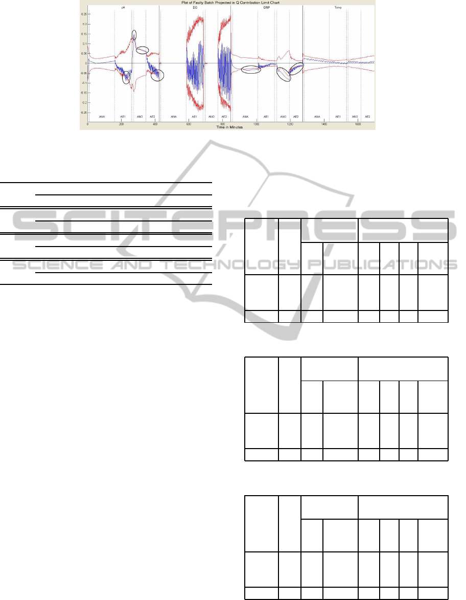
Figure 1: Q contribution limit chart for AOC batch 1.
Table 1: Fault signature for AOC batch 1. For reason of
space, the FS vector has been divided into four sections.
pH
F1 ANA AE1 F2 ANO AE2
0 0 14 0 43 17
DO
F1 ANA AE1 F2 ANO AE2
0 0 0 0 0 0
ORP
F1 ANA AE1 F2 ANO AE2
0 84 0 0 71 58
Temp
F1 ANA AE1 F2 ANO AE2
0 0 0 0 0 0
be used to classify the faulty batches and give the di-
agnosis of the batch. After the knowledge model of
the training set was obtained, the model was applied
to the validation set to test the accuracy of the classi-
fication.
5.4 Results
The classification of the different BNR for the pro-
cessed wastewater can be observed in Tables 2, 3, 4.
The tables are divided into four sections: removal,
cases, correctly classified and incorrectly classified.
The removal section contains the different classes of
the BNR (high, medium and low). The cases section
includes the quantity of cases of the different classes
and at the bottom the total cases for the validation.
The correctly classified section is subdivided in two:
the cases, which represents the quantity of cases with
correct classification, and the percentage, which is the
percentage of correct classification. Finally, the in-
correctly classified section is subdivided in four: the
first three columns with the BNR classes indicating in
which class the knowledge model classifies the cases
that were not classified as correct and the percent-
age of incorrect classification. A table for the organic
matter nutrient removal is not necessary since every
case has a high removal efficiency.
The result of the diagnosis generated by the
knowledge model for the ammoniumnutrientremoval
are shown in Table 2, with a correct classification ac-
curacy of 98.84 percent, 97.67 percent for the nitrates
in Table 3 and 98.84 percent for the phosphate in Ta-
ble 4.
Table 2: Ammonium classification.
Removal
Cases
Correctly Incorrectly
Classified Classified
Cases
%
High
Med.
Low
%
High 51 50 98.04 - - 1 1.96
Med. - - - - - - -
Low 35 35 100 - - - -
Total 86 85 98.84 - - 1 1.16
Table 3: Nitrates classification.
Removal
Cases
Correctly Incorrectly
Classified Classified
Cases
%
High
Med.
Low
%
High 45 45 100 - - - -
Med. 41 39 95.12 2 - - 4.88
Low - - - - - - -
Total 86 84 97.67 2 - - 2.33
Table 4: Phosphate Classification.
Removal
Cases
Correct Incorrect
Classified Classified
Cases
%
High
Med.
Low
%
High 35 35 100 - - - -
Med. - - - - - - -
Low 51 50 98.04 1 - - 1.96
Total 86 85 98.84 1 - - 1.16
FAULT DIAGNOSIS OF BATCH PROCESSES RELEASE USING PCA CONTRIBUTION PLOTS AS FAULT
SIGNATURES
227

6 CONCLUSIONS
In this study a software sensor was developed with
the proposed method, a fault signature by means of
PCA contribution plots, to classify qualitative vari-
ables from quantitative variables of the process for
future released batches.
To prove the proposed method a biological nutri-
ent removal (BNR) sequencing batch reactor (SBR)
for wastewater treatment was used as an example of
a batch process. In this example the objective was
the diagnosis of the biological nutrient removal (qual-
itative variable) of the effluent wastewater processed
by classifying the batches detected as faulty. The re-
sult for the diagnosis featured high classification rates
for the faulty batches, where the correct classification
of the nutrients was an accuracy of more than above
97%.
The accuracy of the method to predict the quality
of the product, in this case the processed wastewater,
helps in reduced time to know if the product has a
high biological nutrient removal efficiency, and will
lead to faster action to correct a faulty process. In this
example case, the implementation of the system can
save a high investment with respect to the purchase of
sensors that measure water quality that can cost more
than an entire wastewater plant of small dimensions.
For future studies, applying the method in differ-
ent batch processes would improve the robustness of
the software sensor. Improve representations of the
faulty stages for the fault signature would help clas-
sify qualitative variables and would therefore result in
an accurate diagnosis of the product released.
ACKNOWLEDGEMENTS
The authors wish to thank the Spanish Government
(CTQ2008-06865-C02-02), with the support of the
CUR, the DIUE, the Generalitat of Catalonia and the
European Social Fund.
REFERENCES
Barker, M. and Rawtani, J. (2005). Practical Batch Process
Management. Elsevier.
Cleary, J. G. and Trigg, L. E. (1995). K*: An instance-
based learner using an entropic distance measure. In
12th International Conference on Machine Learning
(1995), pages 108–114.
Fan, L. and Xu, Y. (2007). A pca-combined neural net-
work software sensor for sbr processes. In Liu, D.,
Fei, S., Hou, Z., Zhang, H., and Sun, C., editors, Ad-
vances in Neural Networks ISNN 2007, volume 4492
of Lecture Notes in Computer Science, pages 1042–
1047. Springer Berlin / Heidelberg.
Hong, S. H., Lee, M. W., Lee, D. S., and Park, J. M. (2007).
Monitoring of sequencing batch reactor for nitrogen
and phosphorus removal using neural networks. Bio-
chemical Engineering Journal, 35(3):365 – 370.
Kim, Y., Bae, H., Poo, K., Kim, J., Moon, T., Kim, S., and
Kim, C. (2006). Soft sensor using pnn model and rule
base for wastewater treatment plant. In Wang, J., Yi,
Z., Zurada, J., Lu, B.-L., and Yin, H., editors, Ad-
vances in Neural Networks - ISNN 2006, volume 3973
of Lecture Notes in Computer Science, pages 1261–
1269. Springer Berlin / Heidelberg.
Kourti, T. (2005). Application of latent variable methods
to process control and multivariate statistical process
control in industry. Int. J. Adapt. Control, 19:213–246.
Lee, D. S. and Park, J. M. (1999). Neural network mod-
eling for on-line estimation of nutrient dynamics in
a sequentially-operated batch reactor. Journal of
Biotechnology, 75(2-3):229 – 239.
Lee, Y.-H., Lee, D.-Y., and Han, C. (1999). Rmbatch: Intel-
ligent real-time monitoring and diagnosis system for
batch processes. Computers & Chemical Engineer-
ing, 23(Supplement 1):S699 – S702. European Sym-
posium on Computer Aided Process Engineering, Pro-
ceedings of the European Symposium.
Leung, D. and Romagnoli, J. (2002). An integration mech-
anism for multivariate knowledge-based fault diagno-
sis. Journal of Process Control, 12(1):15 – 26.
Nomikos, P. and MacGregor, J. F. (1994). Monitoring batch
processes using multiway principal component analy-
sis. AIChE J., 40(8):1361–1375.
Nomikos, P. and MacGregor, J. F. (1995). Multivariate spc
charts for monitoring batch processes. Technometrics,
37(1):41–59.
Puig, S., Corominas, L., Balaguer, M., and Colprim, J.
(2007). Biological nutrient removal by applying sbr
technology in small wastewater treatment plants: Car-
bon source and c/n/p ratio effects. Water Sci. Technol.,
55(7):135–141.
Westerhuis, J. A., G., S. P., and Smilde, A. K. (2000).
Generalize contribution plots in multivariate statisti-
cal process monitoring. Chemom. Intell. Lab. Syst.,
51:95–114.
Wold, S., Esbensen, K., and Geladi, P. (1987). Princi-
pal component analysis. Chemom. Intell. Lab. Syst.,
2(1):37–52.
Wong, A., Colomer, J., Coma, M., and Colprim, J. (2010).
Pca intelligent contribution analysis for fault diagno-
sis in a sequencing batch reactor. In Proceedings of
the iEMSs Fifth Biennial Conference, volume 3, pages
2230–2237.
Xiao, F., Wang, S., Xu, X., and Ge, G. (2009). An isolation
enhanced pca method with expert-based multivariate
decoupling for sensor fdd in air-conditioning systems.
Applied Thermal Engineering, 29(4):712 – 722.
ICEIS 2011 - 13th International Conference on Enterprise Information Systems
228
