
TOPOLOGICAL MODELING FOR ENTERPRISE DATA
SYNCHRONIZATION SYSTEM
A Case Study of Topological Model-driven Software Development
Uldis Donins
1,2
and Janis Osis
1
1
Department of Applied Computer Science, Institute of Applied Computer Systems, Riga Technical University
Meza iela 1/3, Riga, LV 1048, Latvia
2
Software Development Department, Lattelecom Technology Ltd., Dzirnavu iela 16, Riga, LV 1010, Latvia
Keywords: Model driven development, Topological modelling, Software design and architecture.
Abstract: In this paper a problem domain and system modelling formalization approach is shown in context of
enterprise data synchronization system development case study. Formalization approach is based on
topology borrowed from topological functioning model (TFM). TFM uses mathematical foundations that
holistically represent complete functionality of the problem and application domains. By applying the
proposed topological modelling approach in software development process we aim to enable computation
independent model creation in a formal way and to enable transformation from it to platform independent
model. Besides that a traceability can be established between problem domain model, solution domain
model (or models) and the software code.
1 INTRODUCTION
According to Jones (Jones, 2009) the way software
is built remains surprisingly primitive (by meaning
that major software applications are cancelled,
overrun their budgets and schedules, and often have
hazardously bad quality levels when released). We
are consuming that by formalizing the very
beginning of the software development life-cycle it
is possible to build a better quality software systems.
The main drawback of the most software
development methods or approaches is that the
beginning of the software development is too fuzzy
and lacking a good structure. Therefore, for
example, the CIM-to-PIM (Computation
independent model to Platform independent model)
conversion depends much on designers’ personal
experience and knowledge and the quality of PIM
can not be well controlled (Osis, Asnina, 2008)
(Zhang, et al., 2005). In the (Loniewski, et al., 2010)
is stated that only a few methods include the
requirements discipline in the Model-Driven
Development process.
The proposed topological modelling approach
enables requirements modelling and validation
against the functioning of the business system. Thus
missing requirements are found and a new
functionality for the business system is identified.
By applying the proposed topological modelling
approach in software development process we aim to
enable CIM creation in a formal way and to enable
transformation from CIM to PIM. Besides that a
traceability can be established between problem
domain model, solution domain model (or models)
and even the software code.
The topological modelling approach for business
systems modelling and software systems designing
is a model-driven approach. It combines Topological
Functioning Model (TFM) (Osis, Asnina, 2008) and
its formalism with elements and diagrams of
TopUML (Osis, Donins, 2010) (a profile based on
Unified Modeling Language (UML) (OMG, 2010)).
The TFM holistically represents a complete
functionality of the system from the computation
independent viewpoint (in the context of Model
Driven Architecture – MDA (Miller, Mukerji,
2003)). It considers problem domain information
separate from the solution domain information. The
TFM is an expressive and powerful instrument for a
clear presentation and formal analysis of system
functioning and the environment the system works
within. The UML is a graphical language for
visualizing, specifying, constructing, and
87
Donins U. and Osis J..
TOPOLOGICAL MODELING FOR ENTERPRISE DATA SYNCHRONIZATION SYSTEM - A Case Study of Topological Model-driven Software
Development.
DOI: 10.5220/0003503000870096
In Proceedings of the 13th International Conference on Enterprise Information Systems (ICEIS-2011), pages 87-96
ISBN: 978-989-8425-55-3
Copyright
c
2011 SCITEPRESS (Science and Technology Publications, Lda.)

documenting the artefacts of a software-intensive
system. The UML offers a standard way to write a
system's blueprints, including conceptual things such
as business processes and system functions as well
as concrete things such as programming language
statements, database schemas, and reusable software
components. (Fowler, 2003) and (Rumbaugh, et al.,
2004)
The main idea of this paper is to explore a case
study of applying topological modelling approach in
real software project. In this software project a
service application was developed. This service
application is aimed to synchronize enterprise
employee data. Synchronization is done by taking
data from multiple data sources and placing in one
central data storage. The case study includes full
software development life cycle (at the time when
this paper was written the implementation phase was
completed and the software was forwarded to the
maintenance phase, so the case study covers the full
implementation phase).
In order to better illustrate topological modelling
approach and our case study, the paper is divided in
two large parts. The first part (section 2) gives the
theoretical basis for topological modelling approach.
The second part (section 3) explores in detail case
study (in the context of given theory) by showing
how all the steps of topological modelling approach
are implemented. The section 4 gives conclusions of
our case study and sketches future researches.
2 TOPOLOGICAL MODELING
APPROACH
Topological modeling approach is based on
formalism of Topological Functioning Model
(TFM). TFM has topological characteristics:
connectedness, closure, neighborhood, and
continuous mapping. Despite that any graph is
included into combinatorial topology, not every
graph is a topological functioning model. A directed
graph becomes the TFM only when substantiation of
functioning is added to the above mathematical
substantiation. The latter is represented by functional
characteristics: cause-effect relations, cycle
structure, and inputs and outputs. It is acknowledged
that every business and technical system is a
subsystem of the environment. Besides that a
common thing for all system (technical, business, or
biological) functioning should be the main feedback,
visualization of which is an oriented cycle.
Therefore, it is stated that at least one directed
closed loop must be present in every topological
model of system functioning. It shows the “main”
functionality that has a vital importance in the
system’s life. Usually it is even an expanded
hierarchy of cycles. Therefore, a proper cycle
analysis is necessary in the TFM construction,
because it enables careful analysis of system’s
operation and communication with the environment
(Osis, Asnina, 2008).
Topological modelling approach consists of five
steps:
1) Construction of Topological Functioning Model
(see section 2.1)
2) Functional requirements validation (see section
2.2)
3) Elaboration of problem domain objects graph
(see section 2.3)
4) Acquisition of sequence diagrams (see section
2.4)
5) Development of Topological Class Diagram (see
section 2.5)
2.1 Construction of Topological
Functioning Model
The TFM has strong mathematical basis and is
represented in a form of a topological space (X, Q),
where X is a finite set of functional features of the
system under consideration, and Q is the topology
that satisfies axioms of topological structures and is
represented in a form of a directed graph. Within
previous researches there are stated three steps for
developing TFM of system functioning, (Osis,
Asnina, 2008):
Step 1: Definition of physical or business functional
characteristics, which consists of the following
activities: 1) definition of objects and their
properties from the problem domain description; 2)
identification of external systems and partially-
dependent systems; and 3) definition of functional
features using verb analysis in the problem domain
description, i.e., by finding meaningful verbs.
As a result of this step a set of functional features
are defined. At the lowest abstraction level one
functional feature should describe only one atomic
business action. Atomic business action means that
it cannot be further divided into set of business
actions. By using the topological characteristic
(continuous mapping) of TFM, the abstraction level
of functional features can be raised at any time when
needed.
Within the (Asnina, 2006) it is suggested that
each functional feature is a tuple (1) (within (Osis,
ICEIS 2011 - 13th International Conference on Enterprise Information Systems
88

Donins, 2009) are proposed additional elements in
tuple of functional feature):
<A, R, O, PrCond, PostCond, E, Cl, Op>. (1)
Description of functional feature tuple’s elements
can be found in (Osis, Donins, 2009).
Step 2: Introduction of topology
(in other words –
creation of topological space), which means
establishing cause and effect relations between
identified functional features. Cause-and-effect
relations are represented as arcs of a directed graph
that are oriented from a cause vertex to an effect
vertex. Topological space Z is a system represented
by Equation (2), where N is a set of inner system
functional features and M is a set of functional
features of other systems that interact with the
system or of the system itself, which affect the
external ones.
Z = N M
(2)
Step 3: Separation of the topological functioning
model from the topological space of a problem
domain, which is performed by applying the closure
operation (3) over a set of system’s inner functional
features (the set N), where X is an adherence point
of the set N and capacity of X is the number n of
adherence points of N.
n
XNX
1
(3)
Construction of TFM can be iterative. Iterations are
needed if the information collected for TFM
development is incomplete or inconsistent or there
have been introduced changes in system functioning
or in software requirements.
2.2 Functional Requirements
Validation
After construction of TFM, the next step is the
validation of functional requirements in
conformance with the constructed TFM. Functional
features specify functionality that exists in the
problem domain, but requirements specify
functionality that should exist in the solution
domain. Therefore it is possible to make mappings
between requirements and functional features of the
TFM. As a result of requirements validation, both
TFM and requirements are checked.
In (Osis, Asnina, 2008) it is suggested to
represent requirement mappings between functional
requirements and functional features by using arrow
predicates. An arrow predicate is a construct in
universal categorical logic. Universal categorical
(arrow diagram) logic for computer science is
explored in detail in (Diskin, et al., 2000).
There are five types of mappings and
corresponding arrow predicates defined for mapping
requirements onto TFM: 1) One to One; 2) Many to
One; 3) One to Many; 4) One to Zero; and 5) Zero to
One.
2.3 Elaboration of Problem Domain
Objects Graph
According to (Osis, Asnina, 2008) in order to obtain
a problem domain object graph, it is necessary to
detail each functional feature of the TFM to a level
where it uses only one type of objects (see Figure 1).
Figure 1: Relations between Topological Functioning
Model and Problem Domain Objects Graph.
By using the modified version (Osis, Donins,
2009) of this approach it is possible to define
conceptual operation definitions. Operations can be
obtained from functional features because one
functional feature is one atomic business action.
Since the static structure representation of system
should show not only objects and their operations
involved into system’s realization, during TFM
transformation attributes of objects also should be
acquired. This can be achieved by taking into
consideration attributes of the entity represented by
functional feature.
2.4 Acquisition of Sequence Diagrams
Sequence diagrams (OMG, 2010) are developed by
transforming problem domain objects graph. During
problem domain objects graph transformation all
vertices with the same type of objects should be
merged. While merging problem domain objects
graph all relations between vertices should be kept.
The relations from this graph will serve as message
sending between objects in sequence diagrams.
The scope of sequence diagram is determined by
system goal or by functional requirement. For each
system goal an expert should find corresponding
functional features in TFM (if functional
requirements are used, then corresponding
functional features are determined during
requirements validation). The expert should find an
input and an output functional feature for each
TOPOLOGICAL MODELING FOR ENTERPRISE DATA SYNCHRONIZATION SYSTEM - A Case Study of
Topological Model-driven Software Development
89
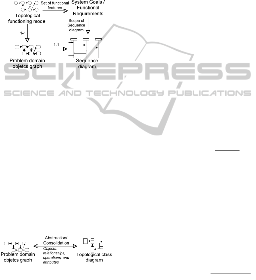
system goal/requirement – all functional features
that correspond to particular system
goal/requirement should be in one chain of
functional features. For each system
goal/requirement one sequence diagram should be
developed. Schematic representation of sequence
diagram development is given in Figure 2.
Figure 2: Acquisition of Sequence Diagram.
System goals can be identified by the problem
domain experts. If system goals need to be identified
during problem domain analysis a TFM4MDA
approach can be used (Osis, Asnina, 2008).
TFM4MDA uses goals (Leffingwell, Widrig, 2003)
in order to identify use cases and concepts from the
description of the system (in the form of informal
description, expert interviewing, etc.).
2.5 Development of Topological Class
Diagram
Topological class diagram is developed by
transforming problem domain objects graph. All the
vertices with the same type of objects and operations
of the problem domain object graph should be
merged, while keeping all relations with other graph
vertices. As a result, topological class diagram with
attributes, operations and topological relationships is
defined (Osis, Donins, 2010). Schematic
representation of topological class diagram
development is given in Figure 3.
Figure 3: Development of Topological Class Diagram.
By transforming problem domain object graph an
initial topological class diagram is obtained. This
initial topological class diagram contains classes
(with attributes and operations) and topological
relations between them. A topological relation
shows the control flow within the system. If static
relations should be included (such as associations,
generalization, etc.) then initial topological class
diagram should be refined.
3 TOPOLOGICAL MODELING
CASE STUDY
Topological modelling case study includes both
description of business system together with
requirements (section 3.1) and artefacts produced
with the topological modelling approach (sections
3.2 – 3.8).
3.1 Enterprise Data Synchronization
System
This section contains full specification of data
synchronization system. Specification of data
synchronization system includes informal
description of data synchronization functioning (see
section 3.1), functional requirements defined for
data synchronization software system (see section
3.2), and goals of data synchronization software
system (see section 3.3). In the informal description
of data synchronization system nouns are denoted by
italic, verbs are denoted by bold, and action
preconditions (or postconditions) are underlined
.
3.1.1 Informal System Description
Scheduler every five minutes reads configuration
data from configuration file. Configuration data
includes following parameters: connection
information of input data source, username and
password for reading input data, flag to indicate if
data should be taken from input data source, time at
which to make import from input data source,
connection information of target data source,
username and password for editing data in target
data source, path to import files folder, path to log
folder.
After configuration data is read, scheduler
checks if import from source data base should be
performed. Import from source data base is
performed at specified time which is given in
configuration data as parameter. If import should
be performed from source data base, then
scheduler reads all data from source data base by
using query statement given in configuration file.
After all data is read, scheduler checks if read data
structure is according to specification. Data from
ICEIS 2011 - 13th International Conference on Enterprise Information Systems
90

source data bases has following structure: surname,
forename, job title, address, e-mail address,
telephone number, gender, start date, expiry date,
department, and company code. If data structure is
according to specification, then scheduler puts the
read data into temporal internal table. After
converting read data to temporal internal table every
row from this table is imported into target data
base.
After configuration data is read and import from
source data bases is performed (if needed),
scheduler checks import folder. If CSV file (the
import file) is found in that folder, scheduler reads
the import file. Import file has following structure:
surname, forename, job title, address, e-mail
address, telephone number, gender, start date, expiry
date, department, and company code. Scheduler then
checks that read import file corresponds to
predefined import file structure. If import file
structure is according to specification, then
scheduler converts the read data into temporal
internal table. After converting read data into
temporal internal table every row from this table is
imported into target data base. If import file
structure is not prepared according to specification,
the import file is skipped, moved to processed files
folder and a log file is created in log files folder
stating that particular import file was not imported
into target data base.
For every row scheduler checks if data from a
particular row already exists in target data base. If
data from the particular row exists then update of
existing data is performed in target data base. If
data from the particular row does not exist then
insert of new data is performed in target data base.
By updating or inserting data in target data base
scheduler prepares log file in log files folder for
every import file and for every time data is imported
from source data base. In log file is logged every
data row from temporal internal table in order to
unify log files from different data sources. For every
row from source data an import status is logged.
There are two import statuses: successful and error.
Successful status is logged when import is
successful for particular row. Error status is logged
when import is not successful for particular row
. If
error is logged then error description also is logged
in order to allow data import manager to watch for
un-imported data. After data import is completed the
log file is archived. After importing data from
import file, the import file is moved to processed
files folder.
3.1.2 Functional Requirements
Enterprise data synchronization system has
following functional requirements:
FR1 Employee data synchronization should be done
between input data sources and target data source.
This requirement includes:
FR1/1 By starting synchronization process a
configuration information should be taken from
configuration file;
FR1/2 If needed, data from source data base
should be taken;
FR1/3 Data should be taken from import files in
CSV format;
FR1/4 If import CSV file is with wrong data
structure, the processing of particular file should be
skipped and faulty import file should be logged;
FR1/5 All data obtained from either source data
base or import files should be placed in target data
base; and
FR1/6 When importing data in target data base all
rows from source data should be logged together
with import status for each particular data row.
Enterprise data synchronization system has
following non-functional requirements:
NFR1 Employee data synchronization
mechanism should be implemented in a way that it
runs every 5 minutes after previous data
synchronization has been completed.
NFR2 Synchronization mechanism should run
using Microsoft .NET Framework 4.0 (Nagel, et al.,
2010).
3.2 Functional Features and Topology
of Enterprise Data Synchronization
System
Within enterprise data synchronization software
system development project has been defined 30
functional features (see Table 1). These functional
features were identified during the analysis of
enterprise data synchronization system – the
informal description of it. The only open question
regarding to (Donins, 2010) which remains open is –
when the informal description of system functioning
is finished and sufficient for successful software
system development?
After definition of functional features it is
needed to introduce topology (cause-and-effect
relationships) between those functional features. The
identified cause-and-effect relations between the
defined functional features are illustrated by the
means of the topological space (see Figure 4).
TOPOLOGICAL MODELING FOR ENTERPRISE DATA SYNCHRONIZATION SYSTEM - A Case Study of
Topological Model-driven Software Development
91

Table 1: Functional features of enterprise data synchronization system.
ID Object action Precondition Entity
Inner or
External
1 Creating data synchronization parameters Data import
manager
External
2 Acquiring synchronization parameters Configuration Inner
3 Checking if import from source data base
should be performed
Configuration Inner
4 Creating data in source data base Source data
base
External
5 Reading all data from source data base If import should be performed from
source data base
Scheduler Inner
6 Checking if read data structure is according to
specification
Scheduler Inner
7 Putting the read data into temporal internal
table
If data structure is according to
specification
Scheduler Inner
8 Importing every row from internal table into
target data base
Scheduler Inner
9 Checking import folder Scheduler Inner
10 Creating CSV import file Import file External
11 Reading the import file If CSV file (the import file) is found
in import folder
Scheduler Inner
12 Checking if import file data structure is
according to specification
Scheduler Inner
13 Converting the read data from import file into
temporal internal table
If import file structure is according to
specification
Scheduler Inner
14 Skipping importing of import file If import file structure is not prepared
according to specification
Scheduler Inner
15 Moving import file to processed files folder Scheduler Inner
16 Creating log file in log files folder Scheduler Inner
17 Writing into log file that particular import file
was not imported into target data base
Scheduler External
18 Receiving log file for unimported CSV file Data import
manager
External
19 Checking if data from a particular row already
exists in target data base
Scheduler Inner
20 Updating existing data in target data base If data from the particular row exists Scheduler External
21 Receiving updated information Target data
base
External
22 Insert new data in target data base If data from the particular row does
not exist
Scheduler External
23 Receiving new information Target data
base
External
24 Creating log file in log files folder for import
file processing
If data is read from import file Scheduler Inner
25 Logging data row from temporal internal table Scheduler Inner
26 Logging Successful status If import is successful for particular
row
Scheduler Inner
27 Logging Error status If import is not successful for
particular row
Scheduler Inner
28 Logging error description If error is logged Scheduler Inner
29 Archiving log file If data import is completed Scheduler External
30 Receiving archived import log file Data import
manager
External
ICEIS 2011 - 13th International Conference on Enterprise Information Systems
92

Figure 4: Topological space of enterprise data
synchronization system.
In the Figure 4 is clearly visible that cause-and-
effect relations form functioning cycles. All cycles
and sub-cycles should be carefully analyzed in order
to completely identify existing functionality of the
system. The main cycle (or cycles) of system
functioning should be found and analyzed before
starting further analysis. In enterprise data
synchronization system case study the main
functioning cycle represents getting data from
source data base and import files and editing those
data in target data base. The main functional cycle is
as follows: 2-3-5-6-7-8-24-19-25-26-15-9-11-12-13-
8-24-19-25-26-15-2.
3.3 Topological Functioning Model of
Enterprise Data Synchronization
System
According to Equation (2) the identified functional
features in Table 1 can be split in two sets of
functional features – the set N (set of inner
functional features) the set M (set of external
functional features and system functional features
that affect the external environment):
N = { 2, 3, 5, 6, 7, 8, 9, 11, 12, 13, 14, 15, 16, 19,
24, 25, 26, 27, 28 }; and
M = { 1, 4, 10, 17, 18, 20, 21, 22, 23, 29, 30 }.
In order to get all of the system’s functionality – the
set X – the closuring operation (3) is applied over
the set N. A detailed example of applying closuring
operation (3) can be found in (Osis, Donins, 2010).
The obtained set X (the TFM) after applying
closuring operation (3) is as follows: X={ 2, 3, 5, 6,
7, 8, 9, 11, 12, 13, 14, 15, 16, 17, 19, 20, 22, 24, 25,
26, 27, 28, 29 } (see Figure 5).
Figure 5: TFM of enterprise data synchronization system.
3.4 Functional Requirements
Validation
As stated in section 2.2 the result of requirements
validation is that both TFM and functional
requirements are checked. In order to validate
functional requirements (and of course the
constructed TFM), mappings between functional
requirements and functional features should be
established.
Since in this case study Use Cases (OMG, 2010)
(see Figure 6) are used for requirements modelling,
the set of mappings of functional requirements will
include both functional features and functional
requirements. According to these mappings
«include» and «extend» relationships could be
automatically established between Use Cases.
The mappings are as follows: FR1 = {FR1/[1-
6]}; FR1/1 = {2, 3}; FR1/2 = {5, 6, 7, FR1/5};
FR1/3 = {9, 11, 12, 13, 14, FR1/4, FR1/5}; FR1/4 =
{15, 16, 17}; FR1/5 = {8, 24, 19, 20, 22, FR1/6};
and FR1/6 = {25, 26, 27, 28, 29}.
As it is shown in Figure 6 every requirement is
modeled with use case (FR1 = “Employee data
synchronization”, FR1/1 = “Obtaining configuration
information”, FR1/2 = “Obtaining data from source
data base”, FR1/3 = “Obtaining data from import
files”, FR1/4 = “Logging faulty import file”, FR1/5
= “Importing data in target data base”, FR1/6 =
“Logging import status”). Since actors in use case
diagram show interaction between system and
external systems or entities, they are obtained from
topological space (see Figure 4). The actors are
entities from functional features and the set of actors
are identified by Equation (4), where E is a set of
functional features defining external entities, X is a
set of functional features belonging to TFM and M is
a set of functional features of other systems.
TOPOLOGICAL MODELING FOR ENTERPRISE DATA SYNCHRONIZATION SYSTEM - A Case Study of
Topological Model-driven Software Development
93
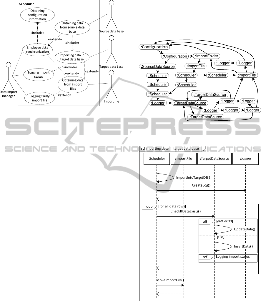
Figure 6: Use case diagram of enterprise data
synchronization system.
E = X \ M (4)
The cause and effect relation between one functional
feature belonging to set E and the other to set X
defines link between use case and actor (since all use
cases are mapped to functional features).
3.5 Objects Model
The next step within topological modelling approach
is development of problem domain objects graph by
transforming TFM of enterprise data
synchronization system functioning. To obtain a
problem domain object graph, it is necessary to
detail each functional feature of the TFM to a level
where it uses only one type of objects. Developed
problem domain objects graph is given in Figure 7.
This graph will be used in order to develop
sequence diagrams in accordance with functional
requirements and to develop topological class
diagram which represents static structure of software
system under consideration.
3.6 Sequence Diagrams
According to process described in section 2.4 a set
of sequence diagrams are obtained by transforming
TFM. Since in this case study use cases are used to
model requirements, the use cases define the number
and the scope of sequence diagrams. The scope of
sequence diagrams defines set of functional features
which are included in each sequence diagram. A
total set of seven sequence diagrams are created.
Figure 8 shows sequence diagram for use case
“Importing data in target data base” (which reflects
functional requirement FR1/5). As FR1/5 mappings
includes also functional requirement FR1/6, the
corresponding sequence diagram contains ref
statement to sequence diagram “Logging import
status”.
Figure 7: Problem domain objects graph of enterprise data
synchronization system.
Figure 8: Sequence diagram “Importing data in target data
base”.
3.7 Initial Topological Class Diagram
Topological class diagram is constructed after
creation of problem domain objects graph by
applying transformation on developed problem
domain objects graph.
ICEIS 2011 - 13th International Conference on Enterprise Information Systems
94
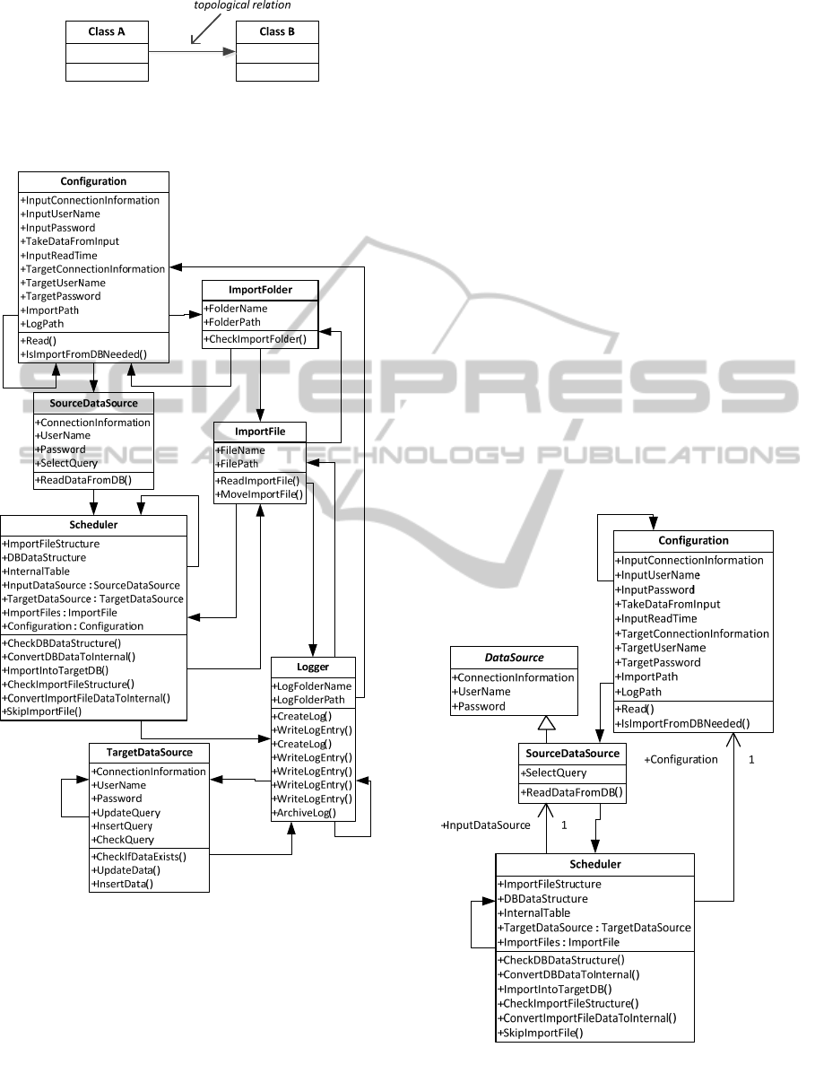
Figure 9: Notation of topological relation notation with
filled triangular arrowhead, cause class (Class A), and
effect class (Class B).
Figure 10: Topological class diagram of enterprise data
synchronization system.
Notation used for representing topological
relationship is directed line with filled triangular
arrowhead pointing to effect class, the opposite end
(without arrowhead) points to cause class. The
notation is shown in Figure 9.
The developed topological class diagram is
shown in Figure 10 (attributes and operations are
obtained during TFM transformation to problem
domain objects graph). This diagram can be
considered as initial topological class diagram
because it contains classes and topological relations
between them and it is at high abstraction level. By
reviewing and refining initial class diagram
associations, generalizations, dependencies, and
other relationships defined in UML are added. In
this way the abstraction level of diagram is lowered
and physical relations between classes are added.
3.8 Refined Topological Class Diagram
The initial topological class diagram is at high
abstraction level showing only classes and
topological relations among them. In order to lower
the abstraction level of initial topological class
diagram, it should be refined by adding static
relations available in UML standard (OMG, 2010)
(such as associations, generalization, etc.). During
refinement associations, generalizations,
dependencies, and enumerations were added (as
shown in Figure 11). Due to the space limitations
only part of the refined topological class diagram is
shown.
Figure 11: Fragment of refined topological class diagram
of enterprise data synchronization system showing
topological, generalization and association relationships.
TOPOLOGICAL MODELING FOR ENTERPRISE DATA SYNCHRONIZATION SYSTEM - A Case Study of
Topological Model-driven Software Development
95

4 CONCLUSIONS
In this paper a case study of applying topological
modelling approach to enterprise data
synchronization system development is shown.
Software development in this context begins with
problem domain formalization in the form of TFM.
Once the TFM has been created, functional
requirements can be validated against it. By doing
this validation we get checked both TFM and
functional requirements. By developing TFM and
validating functional requirements the software
development begins in a very formal way. By
applying transformations to the developed TFM we
can obtain both dynamic and static representations
of the system. In this case study the dynamic aspect
is modelled by sequence diagrams and the static
aspect by topological class diagrams. The initial
topological class diagram shows classes and
topological relations between them. The most
noticeable aspect is that classes and topological
relations are identified in formal way by modelling
problem domain with TFM (in contrast – in tradi-
tional software development scenario relations
(mostly associations and generalizations) between
classes are defined by the modeller’s discretion). In
addition this initial diagram can be refined in order
to obtain associations, generalizations, dependencies
and other artefacts included in UML class diagram.
Case study ends with a software code creation by
using Microsoft Visual Studio (Randloph, et al.,
2010). Example of created software code is not
included in this paper due to the space limitations.
The benefit of applying topological modelling
approach is that software development is done
formal since the very beginning of its lifecycle. Thus
the quality level of software development process
and software itself is elevated and traceability
between different artefacts at different abstraction
levels can be established.
The largest drawback is that at the moment of
implementing this case study there are no tool
support for TopUML. To eliminate this drawback
one of the feature research and work directions is to
create full specification of TopUML profile and to
develop a tool which supports TopUML.
ACKNOWLEDGEMENTS
This work has been supported by the European
Social Fund within the project “Support for the
implementation of doctoral studies at Riga Technical
University”.
REFERENCES
Asnina, E., 2006. The Formal Approach to Problem
Domain Modelling Within Model Driven Architecture.
In 9
th
International Conference “Information Systems
Implementation and Modelling” (ISIM’06).
Diskin, Z., Kadish, B., Piessens, F., & Johnson, M., 2000.
Universal Arrow Foundations for Visual Modeling. In
Theory and Application of Diagrams (pp. 345-360).
Springer-Verlag.
Donins, U., 2010. Software Development with the
Emphasis on Topology. In Advances in Databases and
Information Systems, Lecture Notes in Computer
Science Vol.5968 (pp. 220-228). Springer-Verlag.
Fowler, M., 2003. UML Distilled: A Brief Guide to the
Standard Object Modeling Language, Addison-
Wesley. USA, 3
rd
edition.
Jones, C., 2009. Positive and Negative Innovations in
Software Engineering. In International Journal of
Software Science and Computational Intelligence
Volume 1, Issue 2. IGI Publishing.
Leffingwell, D., Widrig, D., 2003. Managing Software
Requirements: a use case approach, Addison-Wesley.
USA, 2
nd
edition.
Loniewski, G., Insfran, E., & Abrahao, S., 2010. A
systematic Review of the Use of Requirements Engi-
neering Techniques in Model-Driven Development. In
Model Driven Engineering Languages and Systems
(pp. 214-227). Springer-Verlag.
Miller, J., Mukerji, J. (eds), 2003. MDA Guide Version
1.0.1. OMG.
Nagel, C., Evjen, B., Glynn, J., Watson, K., & Skinner,
M., 2010. Professional C# 4.0 and .NET 4, John Wiley
& Sons. USA, 1
st
edition.
OMG, 2010. Unified Modeling Language Infrastructure
version 2.1.3. OMG.
Osis, J., Asnina, E., 2008. Enterprise Modeling for
Information System Development within MDA. In 41
st
Annual Hawaii International Conference on System
Sciences (HICSS 2008).
Osis, J., Donins, U., 2009. An Innovative Model Driven
Formalization of the Class Diagrams. In 4
th
International Conference on Evaluation of Novel
Approaches to Software Engineering (ENASE 2009).
INSTICC Press.
Osis, J., Donins, U., 2010. Platform Independent model
Development by Means of Topological Class
Diagrams. In Model-Driven Architecture and
Modeling Theory-Driven Development. SciTePress.
Randolph, N., Gardner, D., Anderson, C., Minutillo, M.,
2010. Professional Visual Studio 2010, John Wiley &
Sons. USA, 1
st
edition.
Rumbaugh, J., Jacobson, I., & Booch, G., 2004. The
Unified Modeling Language Reference Manual,
Addison-Wesley. USA, 2
nd
edition.
Zhang, W., Mei, H., Zhao, H., & Yang, J., 2005.
Transformation from CIM to PIM: A Feature-Oriented
Component-Based Approach. In Model Driven
Engineering Languages and Systems (pp. 248-263).
Springer-Verlag.
ICEIS 2011 - 13th International Conference on Enterprise Information Systems
96
