
GOAL DRIVEN ITERATIVE SOFTWARE PROJECT
MANAGEMENT
Yves Wautelet
1
and Manuel Kolp
2
1
Faculteit Economie en Management, Hogeschool-Universiteit Brussel, Brussels, Belgium
2
Louvain School of Management, Dept of Operation and Information Systems, Universit´e catholique de Louvain
Louvain-la-Neuve, Belgium
Keywords:
Iterative development, Agent-oriented software engineering, i* modeling, Software project management.
Abstract:
Iterative development has gained popularity in the software industry notably in the development of enterprise
applications where requirements and needs are difficult to express for the users and business processes difficult
to understand by analysts. Such a software development life cycle is nevertheless often used in an ad-hoc
manner. Even when templates such as the Unified Process are furnished, poor documentation is provided
on how to breakdown the project into manageable units and to plan their development. This paper defines a
template for agent-oriented iterative development as well as a software project management framework to plan
the project iterations. The agent paradigm is used at analysis level with actors’ goals considered as piecing
elements, an iterative template is proposed for planning purpose. High-level risk and quality issues focus on
prioritizing the project goals so that each element’s “criticality” can be evaluated and a model-driven schedule
of the overall software project can be set up. The software process is illustrated with the development of a
production planning system for a steel industry.
1 INTRODUCTION
Due to benefits and advantages such as efficient soft-
ware project management, continuous organizational
modeling and requirements acquisition, early im-
plementation, continuous testing and modularity, it-
erative development is more and more adopted by
software engineering professionals especially through
methodologies such as the Unified Process (Kruchten,
2003). The idea governing the iterative approach is
to decompose a software development process into
a series of manageable entities avoiding to face as a
whole every aspect of the project. Moreover, vari-
able and non measurable effort is spent on each of
the engineering disciplines during each of the iter-
ations for fast prototyping and early testing. Obvi-
ously, the most risky issues i.e., the most difficult to
be expressed by the users, understood by the analysts
or those addressing the most sensitive issues (such
as security, flexibility, adaptability,...) receive highest
priority. Consequently, these ”critical” questions are
dealt with first so that the development team receives
feedback from users and from the whole system en-
vironment early on. This improves the probability of
adequately meeting user requirements and getting an
adequate adoption of the system into its environment.
Most software methodologies based on the agent
paradigm use a pure waterfall software development
life cycle (SDLC) or advise their users to repeat stages
”iteratively” during the project in an ad-hoc way. One
main reason resides in the fact that no theoretical
framework to support this way of proceeding has ever
been defined and published. We believe that iterative
development requires a formal or semi-formal man-
agerial framework to support dynamic requirements
and risk-driven development planning so that we re-
quire an adequate way of breaking the software prob-
lem into independent manageable entities and then to
prioritize them to plan their development and evaluate
their achievement.
Tropos (Castro et al., 2002) is an agent-oriented
requirement-driven methodology that uses the i* (i-
star) modeling framework (Yu, 1995; Yu, 2011) dur-
ing the analysis stage; i* defines advanced organiza-
tional modeling features and semantics in the form
of agents, goals, tasks and resources. This allows
to partition a software problem on the basis of the
agent paradigm, the main reason we have chosen to
extend Tropos with an iterative template and use the
i* goals as fundamental entities to decompose the
44
Wautelet Y. and Kolp M..
GOAL DRIVEN ITERATIVE SOFTWARE PROJECT MANAGEMENT.
DOI: 10.5220/0003504300440053
In Proceedings of the 6th International Conference on Software and Database Technologies (ICSOFT-2011), pages 44-53
ISBN: 978-989-8425-77-5
Copyright
c
2011 SCITEPRESS (Science and Technology Publications, Lda.)
problem into several aspects. Let us note that the
research is actually generic enough to be adopted to
extend other agent-oriented software methodologies.
Iterative planning is here based on the i* strategic
dependency diagram’s goals. Moreover, when plan-
ning a project with an iterative SDLC, one needs a
generic process template. For this matter, we define,
in this paper, an ”UP-compliant” reference framework
in line with existing theory on iterative SDLCs. The
contributions of this paper include this iterative tem-
plate and a planning method illustrated with a running
example based on the development of a production
management system in the steel industry.
The paper is structured as follows: Section 2
overviewsa proposal for an iterative template for Tro-
pos developments. Section 3 presents a MDA (model-
driven architecture) method for iterative planning in
the context of I-Tropos developments. This method
deal with threats and quality factors as fundamental
criterias for goal prioritization. Section 4 points to
related work and finally Section 5 gives the reader a
conclusion.
2 ITERATIVE TEMPLATE
The first proposal of this paper is to adopt the tradi-
tional Tropos models and stages to define a project
management template used to drive the software pro-
cess. We also propose a common engineering termi-
nology.
An ”I-Tropos development” is an extension of the
Tropos methodology, made of disciplines iteratively
repeated while the relative effort spent on each one is
variable from one iteration to another. The phase and
discipline notions are often presented as synonyms in
the software engineering literature. Indeed, Tropos is
described in (Castro et al., 2002) as composed of five
phases (Early Requirements, Late Requirements, Ar-
chitectural Design, Detailed Design and Implemen-
tation). However, the Software Process Engineering
Metamodel (OMG, 2005) defines a discipline as a
particular specialization of Package that partitions
the Activities within a process according to a common
”theme”, while a phase is defined as a specialization
of WorkDefinition such that its precondition defines
the phase entry criteria and its goal (often called a
”milestone”) defines the phase exit criteria. The Uni-
fied Process (Kruchten, 2003) defines disciplines as a
collection of activities that are all related to a major
”area of concern” while the phases here are not the
traditional sequence of requirements analysis, design,
coding, integration, and test. They are completely or-
thogonal to the traditional phases. Each phase is con-
cluded by a major milestone. In order to be compliant
with the most generic terminology, traditional Tropos
phases will be called disciplines in our software pro-
cess description since “they partition activities under
a common theme”. In the same way, phases will be
considered as groups of iterations which are work-
flows with a minor milestone.
In I-Tropos, the Organizational Modeling and Re-
quirements Engineering disciplines respectively cor-
respond to Tropos’ Early and Late Requirements dis-
ciplines. The Architectural and Detailed Design dis-
ciplines correspond to the same stages of the tradi-
tional Tropos process. I-Tropos includes core disci-
plines, i.e., Organizational Modeling, Requirements
Engineering, Architectural Design, Detailed Design,
Implementation, Test and Deployment but also sup-
port disciplines to handle the project development
called Risk Management, Time Management, Qual-
ity Management and Software Process Management.
There is little need for support activities in a pro-
cess using a waterfall SDLC since the core disci-
plines are sequentially achieved once for all. How-
ever, for an iterative process, the need for support dis-
ciplines to manage the whole software project is from
primary importance to precisely understand which
project aspect to work on (and through which activ-
ity) at a specific time and with the best resources. I-
Tropos process’ disciplines are described extensively
in (Wautelet, 2008).
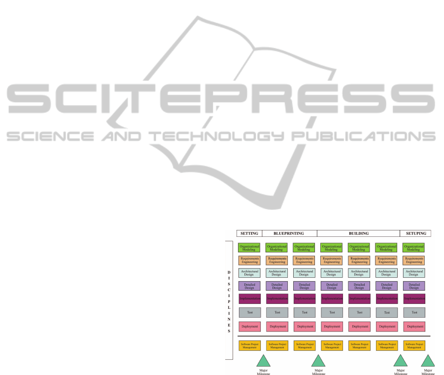
Figure 1: I-Tropos: Iterative Perspective.
Using an iterative SDLC implies repeating pro-
cess’ disciplines many times during the software
project. Each iteration belongs to one of the phases
usually four to six depending on the process itself,
four in our case. We relate to the phases defined
in the UP-based methodologies (RUP, OpenUP, EUP,
...) but are redefined here to better match with the
Tropos specificities. These phases are achieved se-
quentially and have different goals assessed at mile-
GOAL DRIVEN ITERATIVE SOFTWARE PROJECT MANAGEMENT
45

stones through knowledge and achievement oriented
metrics. Phases are informally described into the next
section. Figure 1 offers a two dimensional view of
the I-Tropos process depicting the disciplines on Y-
axis and the four different phases they belong to on
X-axis.
2.1 Core Disciplines
The I-Tropos process has been fully described us-
ing the Software Engineering Process Metamodel in
(Wautelet, 2008) that details each process’ Discipline,
Activity, Role, WorkDefinition and WorkProduct, so
that it can be used as a reference, template, pattern or
guide for managing the system project. A lightened
overview of the is given below. As already pointed
out, the first four disciplines are inspired by the Tro-
pos original stage.
• the Organizational Modeling discipline aims to
understand the problem by studying the existing
organizational setting;
• the Requirements Engineering discipline extends
models created previously by including the sys-
tem to-be, modeled as one or more actors;
• the Architectural Design discipline aims to build
the system’s architecture specification, by orga-
nizing the dependencies between the various sub-
actors identified so far, in order to meet functional
and non-functional requirements of the system;
• the Detailed Design discipline aims at defining the
behavior of each architectural component in fur-
ther detail;
• the Implementation discipline aims to produce an
executable release of the application on the basis
of the detailed design specification;
• the Test discipline aims on evaluating the quality
of the executable release;
• the Deployment discipline aims to test the soft-
ware in its final operational environment.
2.2 Support Disciplines
These support disciplines provide features to support
the software development on a particular project i.e.,
tools to manage threats, quality factors, time, effort,
resources allocation but also the software process it-
self. All those features can be regroupedonto the term
software project management (Jalote, 2002).
• Risk Management is the process of identifying,
analyzing, assessing risk as well as developing
strategies to manage it. Strategies include trans-
ferring risk to another party, avoiding risk, reduc-
ing its negative effects or accepting some or all
of the consequences of a particular one. Techni-
cal answers are available to manage risky issues.
Choosing the right mean to deal with particular
risk is a matter of compromise between level of
security and cost. This compromise requires an
accurate identification of the threats as well as
their adequate evaluation;
• Quality Management is the process of ensuring
that quality expected and contracted with clients
is achieved throughout the project. Strategies in-
clude defining quality issues and the minimum
quality level for those issues. Technical answers
are available to reach quality benchmarks. Choos-
ing the right mean to deal with quality issues is
a matter of compromise between level of quality
and cost. This compromise requires an accurate
identification of the quality benchmarks as well
as their adequate evaluation;
• Time Management is the process of monitoring
and controlling the resources (time, human and
material) spent on the activities and tasks of a
project. This discipline is of primary importance
since, on the basis of the risk and quality analyses,
the global iterations time and human resources
allocation are computed; they are revised during
each iteration;
• Software Process Management is the use of pro-
cess engineering concepts, techniques, and prac-
tices to explicitly monitor, control, and improve
the systems engineering process. The objec-
tive of systems engineering process management
is to enable an organization to produce sys-
tem/segment products according to plan while si-
multaneously improving its ability to produce bet-
ter products. In this context, Software Process
Management regroups the activities aimed to tai-
lor the generic process onto a specific project as
well as improving the software process.
2.3 Process Phases
I-Tropos phases are inspired by UP-based processes
and their milestones are based on the metrics from
((Boehm, 1998)); each phase is made of one or more
iterations. Disciplines are conducted through the
phases sequentially. Each phase has its own goal:
• the Setting phase is designed to identify and spec-
ify most stakeholders requirements, have a first
approach of the environment scope, identify and
ICSOFT 2011 - 6th International Conference on Software and Data Technologies
46

evaluate project’s threats and identify and evalu-
ate quality factors;
• the Blueprinting phase is designed to produce
a consistent architecture for the system on the
basis of the identified requirements, eliminate
most risky features in priority and evaluate
blueprints/prototypes to stakeholders;
• the Building phase is designed to build a working
application and validate developments;
• the Setuping phase is designed to finalize produc-
tion, train users and document the system.
3 ITERATIVE PLANNING
This section describes a method for planning iterative
Tropos developments. The relevant disciplines are il-
lustrated on a running example, the development of
an enterprise information system in the steel industry.
3.1 Running Example: Coking Process
CARSID, a steel production company located in the
Walloon region , is developing a production manage-
ment software system for a coking plant. The aim
is provide users, engineers and workers with tools
for information management, process automation, re-
source and productionplanning, decision making, etc.
Coking is the process of heating coal into ovens to
transform it into coke and removevolatile matter from
it. Metallurgical Coke is used as a fuel and reducing
agent in the production of iron, steel, ferro-alloys, el-
emental phosphorus, calcium carbide and numerous
other production processes. It is also used to produce
carbon electrodes and to agglomerate sinter and iron
ore pellets. The production of coke is one of the steps
of steel making but further details about other phases
of the production process are not necessary to under-
stand the case study.
3.2 Agents for Steel Making
First of all, one question must be answered: How can
an industrial domain such as the steel industry that
seems to belong to the past be interested in agent tech-
nologies? In other words why agent-oriented model-
ing (and development) would be more indicated than
traditional - possibly object - technologies?
The steel industry is by essence an agent-oriented
world. Indeed, factories as a coking plant or a blast
furnace are made of hundreds of different types of
agents: software agents, machines, automates, hu-
mans, sensors, releases, effectors, controllers, pyrom-
eters, mobile devices, conveying belts, etc. These are
agents in the sense that:
• they are autonomous and dedicated to specific
tasks;
• they are situated in a physical environment;
• they can act upon their environment if this is nec-
essary by warning users, proposing solutions or
taking autonomous action.
The whole I-Tropos project profile is illustrated in
Figure 2. Rectangles representthe relativeeffort spent
on each of the disciplines during each of the phases.
Typically, the reader can notice that the effort spent
on analysis disciplines (organizational modeling and
requirements engineering) is higher into the setting
and blueprinting phases and marginal for the building
and setuping ones. On the contrary, the design (archi-
tectural design and detail design) and implementation
ones are marginal for the setting phase (at the early
beginning of the project) and higher in the blueprint-
ing and building phases. The project managementdis-
ciplines (i.e., the support disciplines) are addressed
on a continuous basis with a stronger focus early on
in the project (during the setting phase). We mostly
concentrates in this paper on disciplines and activi-
ties performed during the setting phase since the focus
is to describe a method for iterative planning. More
precisely concerning the engineering disciplines, we
will only focus here on organizational modeling and
requirements engineering since they are the ones re-
quired for model-driven planning. The support disci-
plines will be covered in detail to depict the process of
goal prioritization and development planning. How-
ever, the support discipline Software Process Man-
agement is not covered here since it goes into too
many low-level details than we can afford in this re-
search paper.
Elab #1Elab #1
Org. Modeling
Construction Transition
Tran #1
Construction Transition
Building Setuping
Tran #1
Req. Engineering
Architectural Design
Detailed Design
Implementation
Test
Deployment
Project Management
Blueprinting
Setting
Setting
Blue #1
Setuping
Blue #2 Blue #3
Build #1
Buildt #2
Build #3
Figure 2: I-Tropos profile for the Carsid Coking Plant
project.
GOAL DRIVEN ITERATIVE SOFTWARE PROJECT MANAGEMENT
47
3.3 Engineering Disciplines
The i* framework can be evaluated on a series of
nine features following (Pastor et al., 2011): refine-
ment, modularity, repeatability, complexity manage-
ment, expressiveness, traceability, reusability, scal-
ability and domain applicability. Those features
are exhaustively assessed on the basis of a not sup-
ported/not well supported/well supported scale. No-
tably they enlighten what is clearly needed to ex-
tend the i* framework with mechanisms to manage
granularity and refinement. Indeed, (Pastor et al.,
2011) points out the lacks of mechanisms in i* for
defining granules of information at different abstrac-
tion levels to structure, hierarchise or aggregate the
semantics represented in the model. One of the
flaws of i* is actually that all of the organizational
modeling elements are represented on a unique ab-
straction level with poor hierarchy and composi-
tion/aggregation. Moreover, except for specifying ab-
stract primitives as building blocks, analysts must be
provided with guidelines to model a complete busi-
ness setting through a set of organizational processes.
These building entities could then be enriched into a
set of more specific components that capture a certain
organizational behavior.
These discussions are from primary concern in the
perspective of finding scope elements, i.e., primary
abstractions to drive the whole development process
including support disciplines rather than just software
engineering ones. Instead of defining a new model
reaching those criteria, as proposed in (Estrada et al.,
2006; Pastor et al., 2011; Wautelet et al., 2008), we
rather prefer to provide guidelines to the software an-
alysts in order to specify an i* strategic dependency
model where each of the goals can be taken as input
into the I-Tropos process. Those include:
• a goal must be defined at the highest abstraction
level such as the organizational and strategic lev-
els. Typically a scope element should describe a
conceptual process, e.g., one business process so
that a goal must encapsulate a high level service
provided by the enterprise;
• lower level processes must be represented as tasks
and a task must always be a refinement of a goal;
• goals are expressed independently, overlaps must
be avoided and, if not possible, eventual redun-
dancy among tasks of two different goals are ad-
dressed at a lower level.
By respecting those rules, all the goals of the i*
strategic dependency diagram (SDD) are scope ele-
ments for breaking down the software project into
manageable parts and are taken as input in the sup-
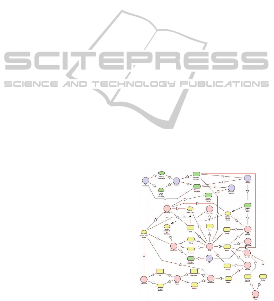
port disciplines as shown in the next sections. Figure
3 (also reproduced at the end of the document) repre-
sents the SDD model built up following those rules on
the CARSID case study. Due to the lack of space we
cannot detail each of the diagram elements here, nev-
ertheless the reader should pay attention to the facts
that:
• Human Actors are represented as circles, for ex-
ample the FADS Team is the team in charge of
handling the coal reception;
• Equipment Actors are also represented as cir-
cles, for example the Coke Car is the automo-
tive wagon that transports the red-hot coke to the
Quenching Tower;
• Resources are represented as rectangles, for ex-
ample Coal is the raw coal received at the coking
plant;
• Goals represented as rounded rectangles, for ex-
ample Baking is the process for which the Oven
Team supervises the baking of the Coal Charge in
the Oven;
• Softgoals represented as clouds, for example
Quality Coke represent the willingness of Man-
agement to insure that the Coke produced in the
coking plant is good as the steel quality depends
on the Coke quality;
• Tasks are represented as hexagonal forms, for ex-
ample Bake is a sub-process of the Baking goal
only concerned with the physical transformation
of the Coal Charge into Coke.
Figure 3: Organizational Modeling.
ICSOFT 2011 - 6th International Conference on Software and Data Technologies
48

3.4 Risk Management
The Risk Management discipline uses the goals iden-
tified into the organizational modeling and require-
ments analysis disciplines as fundamental scope el-
ements. Consequently the identified threats are eval-
uated on the basis of their impact on these elements.
We define a threat as an event that can negatively af-
fect the proper resolution of a goal or that can be the
result of the misuse of a goal execution both in terms
of goal achievement and degradation of quality. A
threat is expressed as an aggregate risk with a quantifi-
cation of the negative impact and a occurrence proba-
bility. A threat is later refined into a series of softgoals
with respect to the transformation process.
Risk analysis was done in collaboration with
stakeholders estimating and validating the possible
threats impact. Risk quantification is done on a dou-
ble basis. Firstly the general threat weight is esti-
mated on the basis of the impact it can have on the
project under development, the system-to-be or the
concerned organization. Secondly, the involvement
of each goal with respect to the risk evoked is eval-
uated following a Low/Medium/High scale. This has
led to the identification of six categories of threats:
• Requirements Poorly Understood: the system
does not run as expected. This threat is partic-
ularly faced by user-intensive software applica-
tions. This kind of risk has a weight of 3 since
huge resources can be devoted to produce an in-
adequate system;
• Facility Damage: it concerns the damages caused
to production facilities. A representative exam-
ple is when the pusher machine pushes while hot
coke is stuck in the oven, resulting in damaging
the pusher machine and/or the oven’s walls. This
kind of risk has a weight of 2 since facilities re-
pairs are cost-intensive;
• Mechanical Error: it concerns errors due to ma-
chinery dysfunction. For instance, a failure in the
coke car engine, making impossible to cool down
the coke. This risk has a weight of 1 since it will
delay production;
• Human Injuries: it concerns injury (or even death)
of the staff and/or workers. A coking plant is a
hazardous place; a replacement worker was re-
cently killed in a coke plant in Ohio, and other
numerous accident of this type took place in the
past. This risk has a weight of 3 since it is very
costly in terms of money and reputation;
• Human Error: it concerns errors due to human
intervention. This risk has a weight of 2 since it
can potentially lead to other risks.
• System Failure: the information system is not
available. The system may be down and cannot
be used for a certain amount of time. This risk
has a weight of 1 because it will delay production.
• Data Loss: some needed data is lost or never ex-
isted. It may happen if one of the worker forgets
to encode some data. This risk has a weight of
2 because it will delay production and can poten-
tially lead to other risks.
On the basis of the organizational model of Figure
3 and the risk analysis, the matrix in Figure 4 sum-
marizes the impact of the identified threats onto the
modeled goals. A specific goal is facing a particu-
lar threat is the marked and a measure is given. For
example the goal Aligning faces the threat Mechani-
cal Error even if the probability of occurence of the
threat on the goal remains Low. The overall risk ex-
posure of each goal is finally computed on the basis
of the threats they faced, the intensity and the threat’s
weight.
3.5 Quality Management
The Quality Management discipline uses the goals
identified into the organizational modeling and re-
quirements analysis disciplines as fundamental scope
elements. Consequently the identified Quality Fac-
tors are envisaged on the basis of their impact on
them. Quality factors must firstly be distinguished
from traditional softgoals in the sense defined in
(Chung et al., 2000). Since we address a higher level
business view of the system to-be, we need an abstrac-
tion where we can specify the quality concerns of the
system rather than its states as softgoals would char-
acterize. In this sense, softgoals describe functions
of a system while quality factors do not. We define
a threat as a constraint onto one or more goals in the
form of a degree of excellence. A quality factor is later
refined into a serie of softgoals in the transformation
process.
Quality analysis was done in collaboration with
stakeholders estimating and validating the possible
quality factors impact. That work has led to the iden-
tification of six categories of quality factors:
• Reliability: Software Reliability is the probability
of failure-prone software operation for a specified
period of time in a specified environment. This
quality factor deals with the question: What level
of trust can be placed in what the system does?
• Efficiency: Software Efficiency deals with execu-
tion time, the later can be influenced by source
code optimization, the use of performing algo-
rithmic techniques, faster sequential execution or
GOAL DRIVEN ITERATIVE SOFTWARE PROJECT MANAGEMENT
49
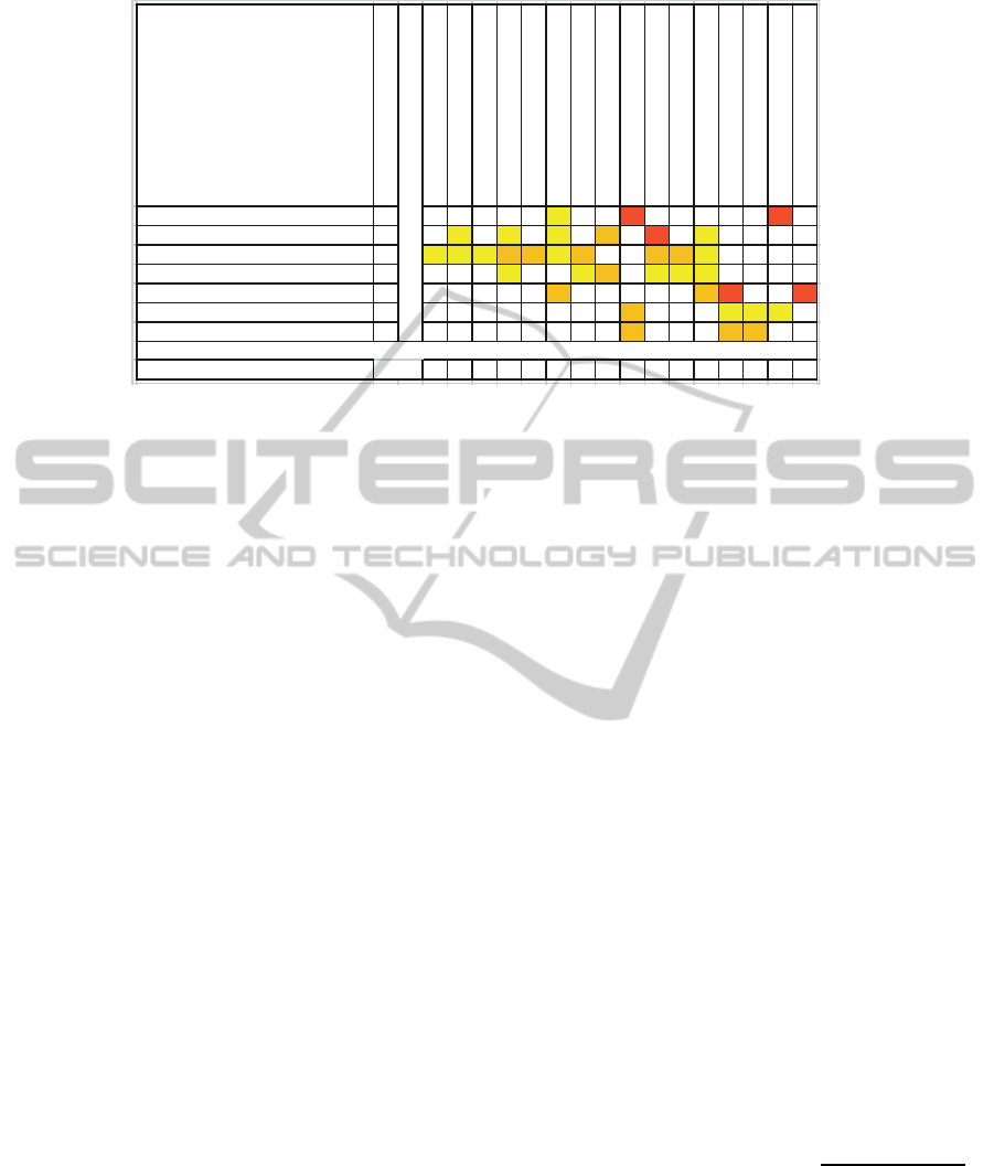
Threat weight
Aligning
Baking
Blending
Charging
Cooling
Creating Pushing Planning
Inversing
Loading
Manage Production Pro cess
Pushing
Reaching Position
Reception Handling
Recording Information
Recording Temperature
Retrieving Information
Setting
Requirements poorly understood HHL3
Facility damage 2 L L L M H L
Mechanical error 1 L L L M M L M M M L
Human injury 3 L L M L L L
Human error HHMM2
System failure LLLM1
Data loss MMM2
80153101531810150127131erusopxEksiRlaoG
Figure 4: Project Goals Risk Exposure.
code parallelization. This quality factor deals with
the question: How well are resources utilized?
• Usability: Software Usability is the capability of
the software product to be understood, learned,
used and attractive to the user, when used un-
der specified conditions. This quality factor deals
with the question: How easy is it to use?
• Integrity: Software Integrity is the ability of soft-
ware to resist, tolerate and recover from events
that threaten its dependability. This quality fac-
tor deals with the question: How secure is it?
• Testability: Software testability is a software char-
acteristic that refers to the ease with which some
formal or informal testing criteria can be satisfied.
This quality factor deals with the question: How
easy is it to verify conformance to requirements?
• Flexibility: Software flexibility is the ability of a
software system to adapt to change. This quality
factor deals with the question: How easy is it to
modify?
• Interoperability: Software interoperability is de-
fined as the ability for multiple software compo-
nents written in different programming languages
and distributed across multiple platforms to com-
municate and interact with one another. This qual-
ity factor deals with the question: How easy is it
to interface with another system?
Based on the organizational model in Figure 3 and
the quality analysis, the matrix in Figure 5 summa-
rizes the impact of the identified quality factors onto
the modeled goals. A goal facing a particular quality
factor is marked and a measure is given, for example
the goal Aligning faces the quality factor Efficiency
even if the concern remains Low. The overall quality
factor exposure of each goal is finally computed on
the basis of the quality factors they faced, the inten-
sity and the quality factor’s weight.
3.6 Time Management
The previous two sections studied the threats and
quality factors impact on the goals from the SDD.
This section uses the global risk and quality expo-
sures to determine a goal priority. Indeed, within the
defined iterative life cycle we will plan the goals’ re-
alization. Goals with highest priority will firstly be
designed, prototyped and tested during the Blueprint-
ing phase and then implemented during the Building
phase. This allows scrutinizing the trickiest issues
first so that risks are addressed early on in the project
when corrective actions are easier and cheaper to put
into practice.
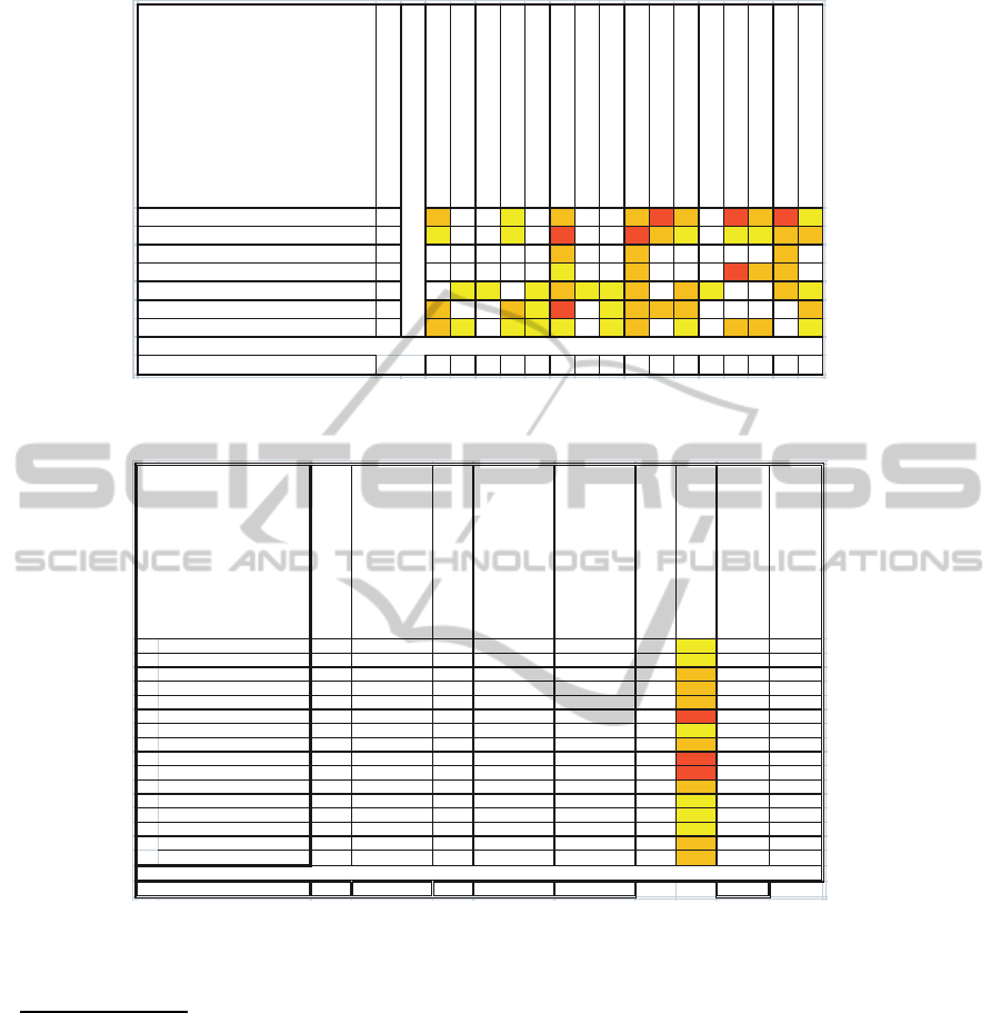
The relevant concepts and their computations are
summarized in Figure 6.Particularly, we emphasize
that:
• The Overall Risk Exposure is the sum of all threats
involvement at any level on one goal;
• The Total Risk Exposure is the sum of the Overall
Risk Exposure of all the project goals;
• On the basis of the Overall Risk Exposure, the
Relative Risk Exposure is computed using the for-
mula: RelativeRiskExposure =
OverallRiskExposure
TotalRiskExposure
;
• The Overall Quality Exposure is the sum of all the
levels of involvement of all the quality factors on
one goal;
• The Total Quality Exposure is the sum of the
Overall Quality Exposure of all the project goals;
• On the basis of the Overall Quality Exposure,
the Relative Quality Exposure is computed us-
ICSOFT 2011 - 6th International Conference on Software and Data Technologies
50
Quality Factor Weight
Aligning
Baking
Blending
Charging
Cooling
Creating Pushing Planning
Inversing
Loading
Manage Production Pro cess
Pushing
Reaching Position
Reception Handling
Recording Information
Recording Temperature
Retrieving Information
Setting
Reliability 3 M L M M H M H M H L
Eciency 2 L L H H M L L L M M
Usability MMM1
Integrity MMHML3
Testability 1 L L L M L L M M L M L
Flexibility 2 M M L H L M M M M
Interoperability 2 M L L L L L M L M M L
Goal Quality Exposure 16 3 1 11 5 31 1 5 32 20 16 1 30 18 26 14
Figure 5: Project Goals Quality Issues.
Overall Risk Exposure
Relative Risk Exposure
Overall Quality Exposure
Relative Quality Exposure
Priority Level
Goal Priority
Goal Complexity
Goal Complexity Weight
Precedence
1 Aligning 1 0,008264463 16 0,069565217 0,023589651 13 L 5
2 Baking 3 0,024793388 3 0,013043478 0,021855911 14 L 5
3 Blending 1 0,008264463 1 0,004347826 0,007285304 16 M 10
4 Charging 7 0,05785124 11 0,047826087 0,055344951 9 M 10
5 Cooling 2 0,016528926 5 0,02173913 0,017831477 15 M 10
6 Creating Pushing Planing 10 0,082644628 31 0,134782609 0,095679123 4 H 15 G4, G10
7 Inversing 5 0,041322314 1 0,004347826 0,032078692 12 L 5
8 Loading 10 0,082644628 5 0,02173913 0,067418254 6 M 10
9 Manage Production Process 18 0,148760331 32 0,139130435 0,146352857 1 H 15
10 Pushing 13 0,107438017 20 0,086956522 0,102317643 3 H 15
11 Reaching Position 5 0,041322314 16 0,069565217 0,04838304 11 M 10
12 Reception Handling 10 0,082644628 1 0,004347826 0,063070428 8 L 5
13 Recording Information 13 0,107438017 30 0,130434783 0,113187208 2 L 5
14 Recording Temperature 5 0,041322314 18 0,07826087 0,050556953 10 L 5
15 Retrieving Information 10 0,082644628 26 0,113043478 0,090244341 5 M 10 G13
16 Setting 8 0,066115702 14 0,060869565 0,064804168 7 M 10
541110321121
Goal
Sum
Figure 6: Goal Prioritization.
ing the formula: RelativeQualityExposure =
OverallQualityExposure
TotalQualityExposure
;
• The Priority Level is computed by ”balancing” the
Relative Risk Exposure and the Relative Quality
Exposure. For this particular project we chose a
repartition key of 75 percent for the risk compo-
nent and 25 for the quality component. This repar-
tition key can vary from one project to another
and should be calibrated from data collected on
a large number of projects as well as considering
the working team experience;
• On the basis of the Priority Level, each Goals Pri-
ority is deduced.
On the basis of the Goal Priority list, the Prece-
dence constraints and the estimated Goal Complex-
ity we instanciate the iteration template defined in
Section 2. The process is summarized in Figure 7.
The Goal complexity estimates the amount of ef-
fort required to develop it. I-Tropos uses three cat-
egories of goal complexity, i.e., Low/Medium/High,
owning respectively a weight of 5/10/15. Transform-
ing the overall weight to man-month requires cali-
bration typically based on a regression model using
statistics from large numbers of projects and remains
an open issue. The proposed planning will be subject
to modifications/reviews during the software project
supported by users and environmental feedbacks.
GOAL DRIVEN ITERATIVE SOFTWARE PROJECT MANAGEMENT
51
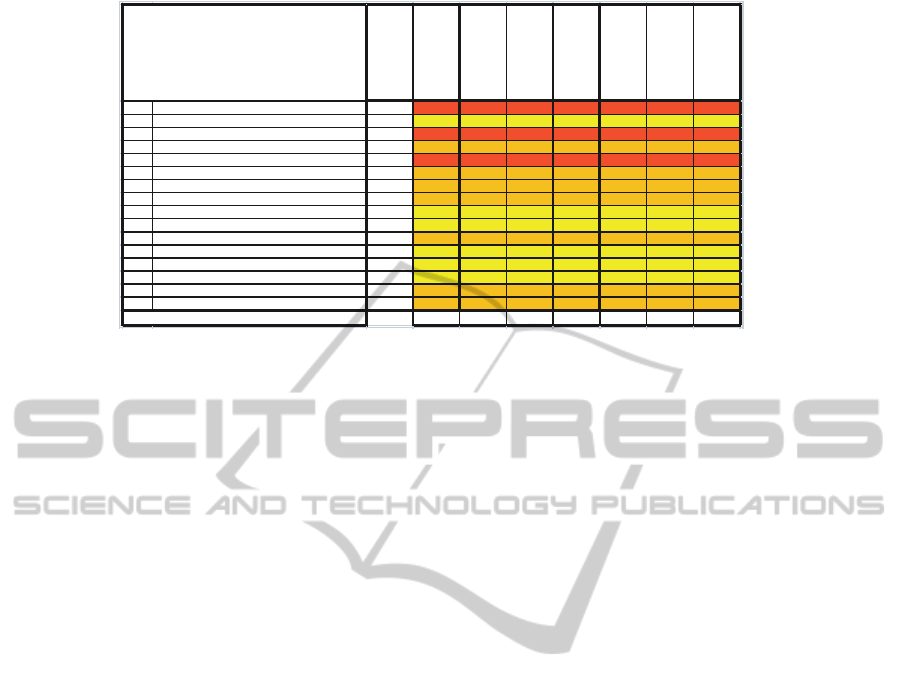
Priority
Complexity
Elaboration 1
Elaboration 2
Elaboration 3
Construction 1
Construction 2
Construction 3
1 Manage Production Process XXH1
2 Recording Information XXL2
3 Pushing XXH3
4 Charging XXM9
5 Creating Pushing Planing XXH4
6 Retrieving Information XXM5
7 Loading XXM6
8 Setting XXM7
9 Reception Handling XXL8
10 Recording Température XXL01
11 Reaching Position XXM11
12 Inversing XXL21
13 Aligning XXL31
14 Baking XXL41
15 Cooling XXM51
16 Blending XXM61
145 15 16,66667 16,66667 30 33,33333 33,33333
Goal
Total Eort Weight
Figure 7: Iteration Plan.
4 RELATED WORK
Numerous agent-oriented software development
methodologies have been proposed in the past twenty
years. We overview hereafter some of them with
a particular focus on iterative SDLC and software
project management. Tropos (Castro et al., 2002)
offers the most advanced agent-based modeling
features through the i* models, one of the reasons
we use it as a basis for the process presented in this
paper. Some papers related to this methodology
propose to develop a software system in an iteratively
way but no supporting theoretical framework has
ever been proposed. Gaia (Zambonelli et al., 2003),
one of the most popular methodologies due to its
simple and clear process as weel as its neutrality
with respect to implementation techniques or plat-
forms has been extended with an iterative SDLC
in (Gonzalez-Palacios and Luck, 2007). The main
drawback of their proposal is that they decompose
functionality on the basis of design models (called
”parts”) and not analysis ones. Moreover, the priority
given to those functional parts is done in an ad hoc
manner since no framework is given to evaluate the
criticality of these ”functional parts”. There is also no
real template provided for cutting out the project into
phases so that each iteration can be considered as a
”sub-waterfall project” with no rapid prototyping for
testing as implied by the cut out between blueprinting
and building phases in our framework. ADELFE
(Bernon et al., 2002) claims to follow the RUP
but no guideline or planning method is actually
given for that purpose. The process is depicted in
(Bernon et al., 2002) in a waterfall manner. Finally,
MASSIVE (Lind, 2001) uses an Iterative View
Engineering approach itself based on Iterative
Enhancement and Round-trip Engineering. From the
authors’ point of view, the method can be said to be
incremental rather than iterative. As a matter of fact,
it is founded on producing hybrid models to be tested
and enhanced later on into the project on the basis
of users’ feedback. However, the software project is
not broken down into manageable elements that are
prioritized and worked on during multiple iterations
so that no software project management framework is
required to manage the SDLC.
5 CONCLUSIONS
Since the emergence of spiral development, software
engineering professionals have learned the benefits of
iterative approaches. However, poor guidelines and
project management frameworks have provided prac-
tioners with clear methods to deal with such SDLCs
in a structured manner. Moreover, MDA (Model-
Driven Architecture) and MDD (Model-Driven De-
velopment) is extensively used in the software trans-
formation process i.e., the process of tracing high
level analysis elements into design and implementa-
tion ones. This principle is applied here but analysis
models are used to feed the process at the managerial
level for goal-driven project management.
Finally, the process needs to gain experience, it
has recently been applied (and has given encouraging
results) on the development of a collaborative supply
chain management platform with an in-depth anal-
ysis of the empirical results. The method can also
be very easily and flexibly adapted to UML use-case
driven development and serve RUP practioners in
their everyday iterative object-oriented development
planning.
ICSOFT 2011 - 6th International Conference on Software and Data Technologies
52

REFERENCES
Bernon, C., Gleizes, M. P., Picard, G., and Glize, P. (2002).
The adelfe methodology for an intranet system design.
In Giorgini, P., Lesp´erance, Y., Wagner, G., and Yu,
E. S. K., editors, AOIS@CAiSE, volume 57 of CEUR
Workshop Proceedings. CEUR-WS.org.
Boehm, B. (1998). Software Project Management.
Addison-Wesley.
Castro, J., Kolp, M., and Mylopoulos, J. (2002). To-
wards requirements-driven information systems engi-
neering: the tropos project. Inf. Syst., 27(6):365–389.
Chung, L., Nixon, B., Yu, E., and Mylopoulos, J. (2000).
Non-functional requirements in software engineering.
Kluwer Academic Publishing.
Estrada, H., Rebollar, A., Pastor, O., and Mylopoulos, J.
(2006). An empirical evaluation of the i* framework
in a model-based software generation environment.
Proceedings of CAiSE, pages 513–527.
Gonzalez-Palacios, J. and Luck, M. (2007). Extending gaia
with agent design and iterative development. In Luck,
M. and Padgham, L., editors, AOSE, volume 4951
of Lecture Notes in Computer Science, pages 16–30.
Springer.
Jalote, P. (2002). Software Project Management in Practice.
Addison Wesley.
Kruchten, P. (2003). The Rational Unified Process : An
Introduction. Addison-Wesley, 3 edition.
Lind, J. (2001). Iterative Software Engineering for Multia-
gent Systems: The MASSIVE Method, volume 1994 of
Lecture Notes in Computer Science. Springer.
OMG (2005). The software process engineering metamodel
specification. version 1.1. Technical report, Object
Management Group.
Pastor, O., Estrada, H., and Mart´ınez, A. (2011). The
strengths and weaknesses of the i* framework: an ex-
perimental evaluation. in Giorgini P., Maiden N., My-
lopoulos J., Eric Yu editors, Social Modeling for Re-
quirements Engineering, in Cooperative Information
Systems series, MIT Press.
Wautelet, Y. (2008). A goal-driven project manage-
ment framework for multi-agent software develop-
ment: The case of i-tropos. Unpublished PhD the-
sis, Universit´e catholique de Louvain, Louvain School
of Management (LSM), Louvain-La-Neuve, Belgium,
August.
Wautelet, Y., Achbany, Y., and Kolp, M. (2008). A service-
oriented framework for mas modeling. In Cordeiro, J.
and Filipe, J., editors, ICEIS (3-1), pages 120–128.
Yu, E. (1995). Modeling strategic relationships for process
reengineering. PhD thesis, University of Toronto, De-
partment of Computer Science, Canada.
Yu, E. (2011). Social Modeling for Requirements Engineer-
ing. MIT Press.
Zambonelli, F., Jennings, N. R., and Wooldridge, M.
(2003). Developing multiagent systems: The gaia
methodology. ACM Trans. Softw. Eng. Methodol.,
12(3):317–370.
GOAL DRIVEN ITERATIVE SOFTWARE PROJECT MANAGEMENT
53
