
AER SPIKE-PROCESSING FILTER SIMULATOR
Implementation of an AER Simulator based on Cellular Automata
Manuel Rivas-Perez, A. Linares-Barranco, A. Jimenez-Fernandez, A. Civit and G. Jimenez
Robotic and Technology of Computers Lab., University of Seville, Av. Reina Nercedes s/n., Seville, Spain
Keywords: Spiking neurons, Address-event-representation, Usb-aer, Vhdl, Fpga, Image filtering, Neuro-inspired,
Cellular automata.
Abstract: Spike-based systems are neuro-inspired circuits implementations traditionally used for sensory systems or
sensor signal processing. Address-Event-Representation (AER) is a neuromorphic communication protocol
for transferring asynchronous events between VLSI spike-based chips. These neuro-inspired
implementations allow developing complex, multilayer, multichip neuromorphic systems and have been
used to design sensor chips, such as retinas and cochlea, processing chips, e.g. filters, and learning chips.
Furthermore, Cellular Automata (CA) is a bio-inspired processing model for problem solving. This
approach divides the processing synchronous cells which change their states at the same time in order to get
the solution. This paper presents a software simulator able to gather several spike-based elements into the
same workspace in order to test a CA architecture based on AER before a hardware implementation.
Furthermore this simulator produces VHDL for testing the AER-CA into the FPGA of the USB-AER AER-
tool.
1 INTRODUCTION
Cellular organization in biology has been an
inspiration in several fields, such as the description
and definition of Cellular Automata (CA). They are
discrete models that consist of a regular grid of cells.
Each cell has an internal state which changes into
discrete steps and knows just one simple way to
calculate the new internal state like a rudimentary
automaton. Cellular activity is carried out
simultaneously like it occurs in biology. Von
Neumann referred to this system as a Cellular Space
that is known currently as Cellular Automata (von
Neumann, 1966).
The first self-reproducing CA, proposed by von
Neumann consisted of a 2D grid of cells, and the
self-reproducing structure was composed of several
hundreds of elemental cells. Each cell presented 29
possible states (Burks, 1970). The evolution rule was
defined as a function of current state of the cell and
its neighbours (up, down, and left). Due to the high
complexity of the model, von Neumann rule has
never been implemented in hardware, but some
partial implementations have been obtained
(Pesavento, 1995).
A CA hardware implementation consists of a
regular 2D array of cells. Each cell is connected to a
neighborhood. The state of each cell is defined by a
set of bits and varies longitudinally according to an
evolution rule. This evolution rule should be the
same for all the cells and it is a function of the
current internal state of the cell and its
neighbourhood (von Neumann, 1966), so it does not
depend on external stimulus. These neighbours are a
fixed set of cells adjacent to the specified cell. A
new generation is created every time the rule is
applied to the whole grid. A global clock signal sets
when the state of the cell is updated.
Address-Event- Representation (AER) is a spike-
based representation technique for communicating
asynchronous spikes between layers of silicon
neurons or spike-processing cells of different chips.
The spikes in AER are carried as addresses of
neurons (called events) on a digital bus. This bio-
inspired approach was proposed by the Mead lab in
1991 (Sivilotti, 1991).
91
Rivas-Perez M., Linares-Barranco A., Jimenez-Fernandez A., Civit A. and Jimenez G..
AER SPIKE-PROCESSING FILTER SIMULATOR - Implementation of an AER Simulator based on Cellular Automata.
DOI: 10.5220/0003525900910096
In Proceedings of the International Conference on Signal Processing and Multimedia Applications (SIGMAP-2011), pages 91-96
ISBN: 978-989-8425-72-0
Copyright
c
2011 SCITEPRESS (Science and Technology Publications, Lda.)
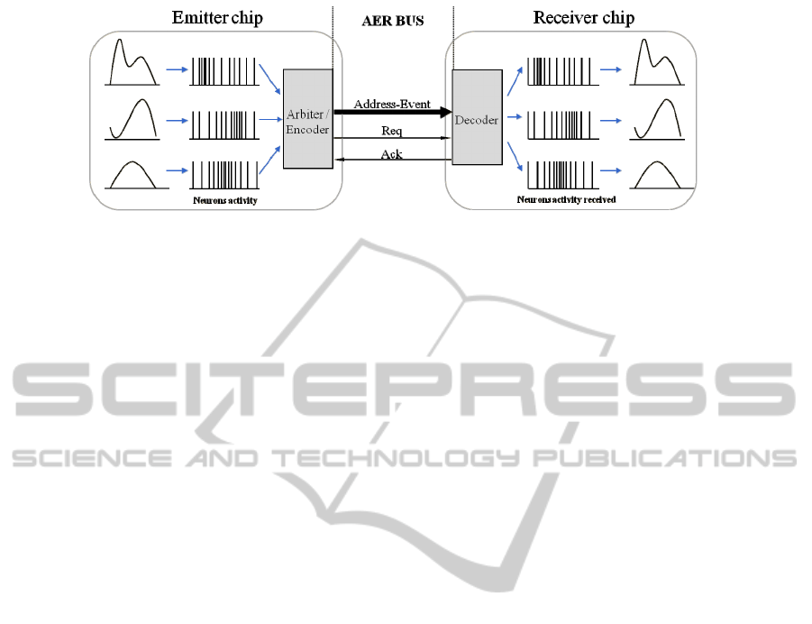
Figure 1: AER inter-chip communication scheme.
The spikes in AER are carried as addresses of
sending or receiving cells on a digital bus. Time
represents itself as the asynchronous occurrence of
the event. An arbitration circuit ensures that neurons
do not access the bus simultaneously. This AER
circuit is usually built using self-timed asynchronous
logic (Boahen, 1998).
Every time a cell generates a spike, a digital
word (address) which identifies the cell, is placed on
an external bus. A receiver chip connected to the
external bus receives the event and sends a spike to
the corresponding cell. In this way, each cell from a
sender chip is virtually connected to the respective
cell in the receiver chip through a single time
division multiplexed bus (See figure 1).
More active cells access the bus more frequently
than less active ones, for example, if the AER
information transmitted by a visual AER sensor is
coded in gray levels, then the number of events
transmitted by a pixel through the bus identifies the
gray level of that pixel.
These AER chips with adequate AER interfaces
allow the construction of multilayered, hierarchical,
and scalable processing systems for visual
processing (Serrano-Gotarredona et al., 2006).
There is a world-wide community of AER
protocol engineers and researchers for bio-inspired
applications in vision and audition systems and robot
control, as it is demonstrated by the success in the
last years of the AER group at the Neuromorphic
Engineering Workshop series (Cohen et al., 2006)
and the CapoCaccia Cognitive Neuromorphic
Engineering Workshop (CNEW, 2011). The goal of
this community is to build large multi-chip and
multi-layer hierarchically structured systems capable
of performing massively-parallel data-driven
processing in real time.
One of the first processing layers in the cortex
consists of applying different kinds of convolution
filters with different orientations and kernel sizes.
Complex filtering processing based on AER
convolution chips have been already implemented,
which are based on Integrate and Fire (IF) neurons
(Serrano-Gotarredonda et al., 2006). When an event
is received, a convolution kernel is added to the
neighbourhood of the targeted neuron. When a
neuron reaches a configurable threshold, a spike is
produced and the neuron is reset. Bi-dimensional
image convolution is defined mathematically by the
following equation, being K an nxm convolution
kernel matrix, X the input image and Y the
convolved image.
∑∑
−=−=
++⋅=→∀
2/
2/
2/
2/
,
),(),(),(
n
na
m
mb
ji
jbiaXbaKjiY
(1)
Each convolved image pixel Y(i,j) is defined by
the corresponding input pixel X(i,j) and weighted
adjacent pixels, scaled by K coefficients. Therefore
an input pixel X(i,j) contributes to the value of the
output pixel Y(i,j) and their neighbours, multiplied
by the corresponding kernel coefficients K.
Digital frame-based convolution processors
implemented in FPGA or CPUs usually measure
their performance by calculating the number of
operations per second (MOPS). There is a
comparative study between frame-based and spike-
based convolution processors in (Linares-Barranco
et al., 2009). In that work, a frame-based 3x3 kernel
convolution processor in a Spartan-III FPGA that
yielded 139 MOPS, were compared to a spike-based
one that yielded 34.61 MOPS for the same kernel.
Nevertheless, frame-based 11x11 kernel convolution
processors decreased their performance to 23
MOPS, while the spike-based processors increased
their performance to 163.51 MOPS. Therefore,
spike-based convolution processors may achieve
higher performances for the same hardware
availability. This has to be thanked to the fully
parallel processing allowed by AER or spike-based
processing.
In a previous work (Rivas-Perez et al., 2010) we
presented an AER-CA 3x3 convolution processor
for visual spike-processing running on a SPARTAN-
SIGMAP 2011 - International Conference on Signal Processing and Multimedia Applications
92

II FPGA at 50MHz, able to yield up to 150 MOPS
for 3x3 kernel sizes, which could imply a
performance of up to 2 GOPS for a possible 11x11
kernel implementation. This work justified the
potential of AER-CA implementations of spike-
based processing.
Another interesting approach for frame-based
neuro-inspired visual processing, and based on
convolutions with high performances are the
ConvNets (Farabet et al., 2009 and Farrig et al.,
2008). ConvNets are based on convolutional neural
networks and have been successfully used in many
recognition and classification tasks including
document recognition (LeCun et al., 86), object
recognition (Huang et al., 2006; Ranzato et al., 2007
and Jarrett et al., 2009), face detection (Osadchy et
al., 2004) and robot navigation (Hadsell et al.,
2009). A ConvNet consists of multiple layers of
filter banks followed by non-linearities and spatial
pooling. Each layer takes as input the output of
previous layer and by combining multiple features
and pooling over space, extracts composite features
over a larger input area. Once the parameters of a
ConvNet are trained, the recognition operation is
performed by a simple feed-forward pass. A
hardware implementation of a 7x7 kernel size
convolver for ConvNets is presented in Farabet et
al., 2009. This system was synthesized for a Virtex 4
and it achieves up to 12GOPS with a 250 MHz clock
that is equivalent to 2.4GOPS for 50MHz clock.
In order to study and develop the correct
configuration of spike-base convolutional neural
networks for a visual processing task based on CA
and AER, it is very important to be able to make
simulations evolving several AER-CA convolution
processors in a network with different kernels.
In this paper we present an AER-CA simulator
developed under C# for spiking convolutional neural
networks that is able to generate VHDL for FPGA
hardware implementation on USB-AER boards
(Gomez-Rodriguez et al., 2006). Next section
introduces how AER and CA can work together for
spike-based visual processing. Section 3 presents the
AER simulator v2.0 with an example for center of
mass object detection. Finally the conclusions are
presented in section 5.
2 AER PROCESSING BASED
ON CELLULAR AUTOMATA
AER neurons carry out an internal processing for
every arriving spike and can produce an output spike
or stream of spikes in response. AER chips develop
hierarchical systems composed of layers of neurons
like a brain. Results of one layer represent the input
of the next layer or a feedback of a previous one.
Furthermore, like in a biological neural system,
several AER devices such as visual sensors (Retina:
Costas-Santos et al., 2007), audio sensors (Cochlea:
Chan et al., 2007), filters (Serrano-Gotarredona,
2006 and Indiveri et al., 2006) and learning chips
(Hafliger, 2007) have been developed, as well as a
set of glue tools (AER tools: Gomez-Rodriguez et
al., 2006.) which facilitate developing and
debugging of these spike-based multi-layer
hierarchical systems, like under the EU CAVIAR
project (Serrano-Gotarredona et al., 2006).
The basic operation in visual processing is the
mathematical convolution. In the previous section
we introduced how a convolution is done using
spike-based visual information. When a set of these
spike-based convolution processors are connected in
a network, more complex visual filtering can be
implemented, like in the brain cortex.
The philosophy of AER systems is lightly different
from CA but also similar in a certain sense. A CA is
a cooperative system, whose evolution depends on
the input, its neighborhood and the time.
Figure 2: AER-CA 3x3 kernel spike based convolution processor scheme.
AER SPIKE-PROCESSING FILTER SIMULATOR - Implementation of an AER Simulator based on Cellular Automata
93

The state of the CA is able to evolve as many times
as necessary with only one input stimulus that
typically represents a change in one cell. A CA can
implement several evolution rules in the same
implementation. Evolution rules are also present in
AER systems, but only between layers. The output
of an AER convolution chip can be seen as the
evolution of the input information. A feed-back
connection and a dynamic kernel are necessary in an
AER convolution processor chip in order to
implement the evolution rules of a CA. This is not
implemented nowadays. Therefore, evolution rule is
found in AER systems between layers of chips, but
not inside one chip.
Then, a CA implemented with AER should be able
to evolve, and take advantage of this evolution
process to improve present AER processors in one
chip.
Let’s suppose a set of spike cells connected in a 2D
grid as a CA. Each cell of this grid is connected to
its eight neighbors. A 3x3 kernel memory is visible
by all the cells. An input spike can be received by
any of the cells as an input stimulus. Every time a
cell receives an input stimulus, this cell sends an
internal stimulus to its eight neighbors and
furthermore it processes the centre of the kernel.
When a cell receives a stimulus from a neighbor,
this cell processes the corresponding element of the
3x3 kernel depending on the source cell of this
internal stimulus. The internal process implemented
by each cell consists of adding the corresponding
kernel value to the internal state. If the internal state
is higher than a configurable threshold, this cell
needs to communicate a new stimulus (a second
generation internal stimulus). Depending on the
convolution kernel and the threshold programmed,
this necessity of communicating a new stimulus can
reflect the detection of an edge in the input visual
information, or any other detected feature of a first
layer of visual processing.
In the case of an AER chip based on IF neurons, this
behavior imply the production of an output spike
(see figure 2). This output information can be the
input of a second layer that will extract a new
feature of the visual information.
In a CA, this situation can be seen as an evolution of
the state of the CA. So the CA is ready to process a
second layer of processing using the same set of
cells thanks to the evolution.
If we suppose that the first layer is processing edge
detection (both vertical and horizontal), a second
layer could be able to detect squares or rectangles if
the second generation of internal stimulus is
processed and transmitted between horizontal and/or
vertical adjacent cells following the next rules:
- When cell C
a,b
receives two different second
generation internal stimulus from different
adjacent cells between a configurable time
window, it means that C
a,b
is the geometric
center between these two detected edges, so a
new third generation of internal stimulus can
be produced.
- If the previous condition is not reached, the
stimulus has to be retransmitted to the opposite
adjacent cell in order to allow a future
detection of the geometrical center by another
cell.
By a correct configuration of these time windows
and directions of retransmission of second, third,
fourth … generation stimulus between adjacent cells
it is possible to detect any shape. Third, fourth,
generations could be used to join basic shapes into
complex ones in order to recognize faces, words, etc.
3 THE C# AER SIMULATOR 2.0.
The simulator architecture is based on two main,
separate but coordinated blocks: a graphical unit
interface (GUI) that allows an easy interaction with
the simulator, and the AER simulator. Figure 3
shows a block diagram example of AER scenario
software architecture of the simulator; and a
captured screen of the GUI. Once the AER system to
be simulated is designed, the user can easily
construct the setup using the mouse and modifying
some parameters through the GUI. This simulator is
composed of several basic library blocks:
- Sequencer for AER traffic production from
static bitmaps.
- Switch for easy AER traffic splitting and
merging.
- Framegrabber for monitoring AER traffic
histograms for a period of time.
- Prototype block for manipulating events. This
block can be configured as a 3x3 AER-CA
convolution based filter, or as a second
generation propagation of stimulus for second,
third… layer operations, as mentioned in the
previous section.
For simulating an AER-CA system with several
layers that will be implemented in hardware with the
same 2D array of cells but with different generations
of stimulus transmissions, in the simulator, for
simplicity, this is shown as several blocks connected
in sequence.
Figure 4 shows a working example simulation
where a sequencer is loaded with a bitmap that
SIGMAP 2011 - International Conference on Signal Processing and Multimedia Applications
94
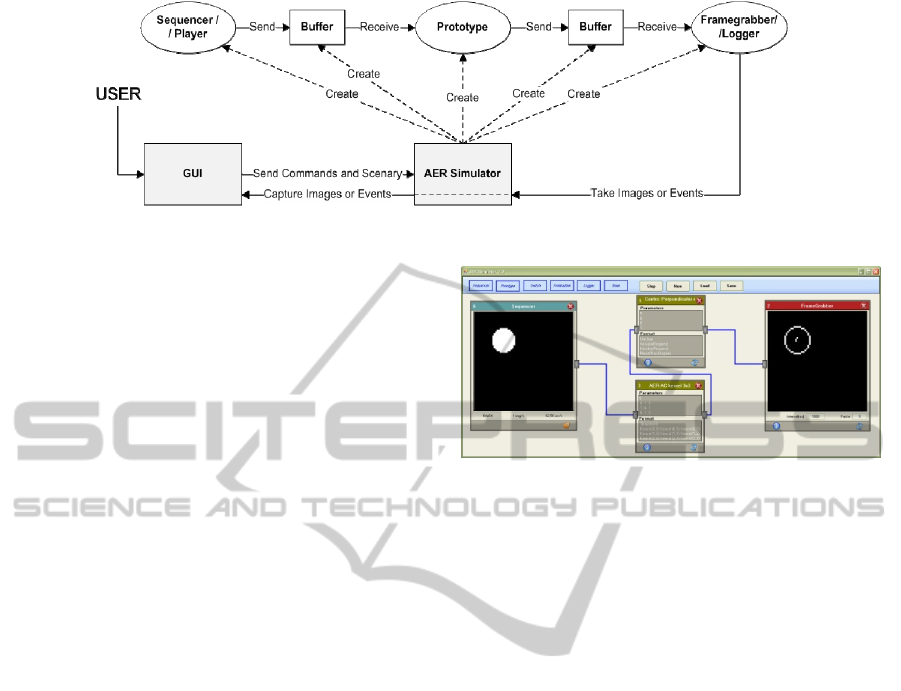
Figure 3: AER Simulator 2.0 block diagram.
produces AER traffic only for those events whose
addresses represent the circle. This AER traffic is
sent to the3x3 AER-CA convolver through a
memory buffer. Those cells that produce output
AER traffic represent the second generation
stimulus. These stimuli are propagated through the
perpendicular neighbors in order to look for a cell
where several second generation stimuli arrive from
different directions. This or these particular cells
represent the center of mass of the object and
produce the third generation of events. In figure 4,
the simulation box number 1 is simulating the
perpendicular propagation of AER, and it is
producing output AER traffic of the center of mass,
but it is also passing through the input events.
Inside the simulator, each box or component block
of the GUI is able to receive or transmit AER from
and to memory buffers. So the AER bus is
implemented in the simulator as memory. The time
information of the spikes is not represented with
timestamps in memory, but it is conserved
depending on when the new AER event is stored on
a buffer and read from it. Every box of the simulator
is implemented as an object. Each object has its own
class depending on the component (sequencer,
Framegrabber, switch or prototype). Each object is
executed with different and independent processes
that communicate with each other through the
memory buffers. A process associated with a box
that produces events stores them on their
corresponding output buffers. And a process
associated with the receiver box will take the next
event on the input buffer and it will execute
necessary operations. When it is necessary this AER
receiver process will generate an output event and
then it will try to process the next input event. If a
buffer is full, the process that is writing events on it
is sent to sleep. If the buffer is empty, the process
reading from it is sent to sleep.
GUI is periodically accessing the bitmaps stored in
all the Framegrabber boxes and they are updated on
the screen.
Figure 4: AER-CA simulation of 2 generations for AER
based center of mass detection.
4 CONCLUSIONS
This paper presents the AER simulator 2.0 for
neuro-inspired AER based system simulations. The
simulator has an easy GUI that allows fast
simulations using sequencer and monitors of events
for input and output AER traffic managing, and a
configurable and expandable block that can
implement 3x3 spike-based convolutions for image
filtering inspired on Cellular Automata (AER-CA)
with several generations of stimulus propagations.
This philosophy allows not only detecting edges on
an image, but also to find the center of mass of basic
shapes. Third, fourth, generations could be used for
object recognitions that are composed of basic
shapes. AER-CA hardware implementations have
demonstrated for 3x3 kernel convolutions
competitive performances of 150MOPS for 50MHz
clocks for small FPGAs (Spartan II 200) that could
be easily improved to more than 2GOPs for
200MHz clocks and 7x7 kernel sizes in higher
capacity and faster FPGAs.
ACKNOWLEDGEMENTS
This work was supported by the Spanish grant
VULCANO (TEC2009-10639-C04-02)
AER SPIKE-PROCESSING FILTER SIMULATOR - Implementation of an AER Simulator based on Cellular Automata
95

REFERENCES
Von Neumann, J., 1966. The Theory of Self-reproducing
Automata, A. Burks, ed., Univ. of Illinois Press,
Urbana, IL.
Burks, A., 1970. Essays on Cellular Automata. Univ.
Illinois Press.
Pesavento, U., 1995. An implementation of von
Neumann’s self-reproducing machine. Artificial Life,
Vol. 2, pp. 337-354.
Sivilotti, M., 1991. Wiring Considerations in analog VLSI
Systems with Application to Field-Programmable
Networks, Ph.D. Thesis, California Institute of
Technology, Pasadena CA.
Boahen, K. A., 1998. Communicating Neuronal
Ensembles between Neuromorphic Chips.
Neuromorphic Systems. Kluwer Academic Publishers,
Boston.
Serrano-Gotarredona, R., Oster, M., Lichtsteiner, P.,
Linares-Barranco, A., Paz-Vicente, R., Gómez-
Rodríguez, F., et al., 2009. CAVIAR: A 45k-neuron,
5M-synapse AER Hardware Sensory-Processing-
Learning-Actuating System for High-Speed Visual
Object Recognition and Tracking, IEEE Trans. on
Neural Networks, Vol. 20. Núm. 9. Pag. 1417-1438.
Cohen, A., et al., 2006. Report to the National Science
Foundation: Workshop on Neuromorphic Engineering,
Telluride, Colorado, USA, June-July 2006.
CNEW, 2011. The 2011 Cognitive Neuromorphic
Engineering Workshop.
Serrano-Gotarredona, R., et al., 2006. A Neuromorphic
Cortical-Layer Microchip for Spike-Based Event
Processing Vision Systems. IEEE T Circuits Systems-
I, Vol. 53, No 12, pp. 2548-2566, Dec-2006.
Linares-Barranco, A., Paz, R., Gómez-Rodríguez, F.,
Jiménez, A., Rivas-Perez, M., Jiménez, G., and Civit
A., 2009. FPGA Implementations comparison of
Neuro-Cortical inspired Convolution Processors for
Spiking Systems. Lecture Notes in Computer Science
Vol. 5517, pp.97-105, 2009.
Rivas-Perez, M., Linares-Barranco, A., Cerda, J.,
Ferrando, N., Jimenez, G., Civit, A., 2010. Visual
Spike-based convolution processing with a Cellular
Automata Architecture. The 2010 International Joint
Conference on Neural Networks (IJCNN). DOI:
10.1109/IJCNN.2010.5596924.
Farabet, C., Poulet, C., Han, J. Y., LeCun, Y., 2009. CNP:
An FPGA-based Processor for Convolutional
Networks. International Conference on Field
Programmable Logic and Applications. FPL 2009.
Farrig, N., Mamalet, F., Roux, S., Yang, F., Paindavoine,
M., 2008. Design of a Real-Time Face Detection
Parallel Architecture Using High-Level Synthesis.
Hindawi Publishing Corporation. EURASIP Journal
on Embedded Systems. Vol. 2008, id 938256.
LeCun, Y., Bottou, L., Bengio, Y., & Haffner, P.
Gradient-based learning applied to document
recognition. Proceedings of the IEEE, 86, 2278–2324.
Huang, F.-J., LeCun, Y., 2006. Large-scale learning with
svm and convolutional nets for generic object
categorization. In Proc. Computer Vision and Pattern
Recognition Conference (CVPR’06). IEEE.
Ranzato, M., Huang, F., Boureau, Y., & LeCun, Y., 2007.
Unsupervised learning of invariant feature hierarchies
with applications to object recognition. In Proc.
Computer Vision and Pattern Recognition Conference
(CVPR’07). IEEE Press.
Jarrett, K., Kavukcuoglu, K., Ranzato, M., & LeCun, Y.,
2009. What is the best multi-stage architecture for
object recognition? In Proc. International Conference
on Computer Vision (ICCV’09). IEEE.
Osadchy, R., Miller, M., & LeCun, Y., 2004. Synergistic
face detection and pose estimation with energy-based
model. In Advances in Neural Information Processing
Systems (NIPS 2004). MIT Press.
Hadsell, R., Sermanet, P., Scoffier, M., Erkan, A.,
Kavackuoglu, K., Muller, U., & LeCun, 2009. Y.
Learning long-range vision for autonomous off-road
driving. Journal of Field Robotics, 26 , 120–144.
Farabet, C., Poulet, C., Han, J. Y., LeCun, Y., 2009. CNP:
an FPGA-based processor for Convolutional
Networks. International Conference on Field
Programmable Logic and Applications (FPL). pp 32-
37. DOI: 10.1109/FPL.2009.5272559.
Gomez-Rodriguez, F., Paz, R., Linares-Barranco, A.,
Rivas M., 2006. AER tools for Communications and
Debugging. Proceedings of the IEEE ISCAS 2006.
Chan, V., Liu, S. C., van Schaik, A., 2007. AER EAR: A
Matched Silicon Cochlea Pair with Address-Event-
Representation Interface. IEEE Trans. Circuits and
Systems-I. Vol. 54, No 1. pp. 48-59. Jan-2007.
Serrano-Gotarredona, R. et al., 2006. A Neuromorphic
Cortical-Layer Microchip for Spike-Based Event
Processing Vision Systems. IEEE T Circuits Systems-
I, Vol. 53, No 12, pp. 2548-2566, Dec-2006.
Costas-Santos, J., Serrano-Gotarredona, T., Serrano-
Gotarredona R. and Linares-Barranco, B., 2007. A
Spatial Contrast Retina with On-chip Calibration for
Neuromorphic Spike-Based AER Vision Systems. IEEE
Trans. Circuits and Systems-I, vol. 54, No. 7, pp.
1444-1458, July 2007
Hafliger, P., 2007. Adaptive WTA with an Analog VLSI
Neuromorphic Learning Chip. IEEE Transactions on
Neural Networks, vol. 18, No 2, pp. 551-572. 2007.
Indiveri, G., Chicca, E., Douglas, R., 2006. A VLSI Array
of Low-Power Spiking Neurons and Bistables
Synapses with Spike-Timig Dependant Plasticity.
IEEE Transactions on Neural Networks, vol. 17, No 1,
pp 211-221. Jan-2006.
SIGMAP 2011 - International Conference on Signal Processing and Multimedia Applications
96
