
SELF-TUNING ALGORITHM AGAINST MAGNETIC
ACTUATOR WIND-UP FOR MILLING SPINDLE
POSITION REGULATION
Nan-Chyuan Tsai, Rong-Mao Lee and Chun-Chi Lin
Department of Mechanical Engineering, National Cheng Kung University, Tainan City, Taiwan
Keywords: Windup, Active Magnetic Bearing, Saturation of Actuator, PID Controller.
Abstract: An Anti-Windup (AW) compensator is applied to the Embedded Cylindrical-Array Magnetic Actuator
(ECAMA) to sustain the performance of spindle position regulation under actuator saturation. Since
ECAMA is a type of Active Magnetic Bearing (AMB), the maximum supplied coil current and the induced
magnetic force are both limited by their extrema. In this work, an AW compensator is proposed and
employed to compensate the output of PID controller to prevent saturation of ECAMA. By employing
commercial software MATLAB/Simulink and signal processing interface, Module DS1104 by dSPACE, the
efficacy of the AW compensation is practically verified by intensive experiments.
1 INTRODUCTION
Windup is generally referred to the saturation
phenomenon of actuators, i.e., the magnitude or rate
of actuator output is limited by an upper bound.
Consequently, the required control input cannot be
realized by the actuator as long as the magnitude of
control input exceeds the saturation level of the
associated actuator (Astrom and Rundqwist, 1989.
Tarbouriech, Queinnec and Garcia, 2007).
In this work, an Anti-Windup (AW) compensator
is applied to the Embedded Cylindrical-Array
Magnetic Actuator (ECAMA) for milling machines
(Tsai and Lee, 2010) to sustain the performance of
spindle position regulation under actuator windup.
Since the maximum supplied coil current and the
induced magnetic force are both limited by the
extrema of ECAMA, the saturation phenomenon
takes place, once the required control input exceeds
the upper limit of the power amplifier. That is, if the
induced magnetic force reaches its upper limit, the
control law will not be applicable any more and
hence the tremble of spindle becomes drastic.
In this work, an AW compensator is employed to
compensate the output of a PID controller to prevent
windup of ECAMA caused by the electric current
saturation at power amplifier.
2 ANTI-WINDUP (AW)
COMPENSATOR
Generally speaking, there are two approaches which
can be adopted to avoid actuator saturation. The first
approach is to take the actuator limit into the
consideration of controller design directly. However,
the design of controller becomes complicated or
cannot be realized for practical applications. The
alternative approach is to separate the prevention of
windup from the controller design. The controller,
without any constrains on actuator, is firstly
designed to meet the performance requirements.
After the controller has been designed, the AW
compensator is developed to ensure closed-loop
system stability.
The concept of AW compensation is depicted
in Fig. 1 (Tarbouriech and Turner, 2009). The
“Unconstrained Controller” is referred to the
controller with no actuator limit has been designed.
The AW compensator output is either the
constrained or unconstrained control input and
defined as follows:
⎪
⎩
⎪
⎨
⎧
<
≤≤
>
=
min min
maxmin
maxmax
for
for
for
uuu
uuuu
uuu
u
s
(1)
where
max
u
and
min
u
are the upper limit and lower
195
Tsai N., Lee R. and Lin C..
SELF-TUNING ALGORITHM AGAINST MAGNETIC ACTUATOR WIND-UP FOR MILLING SPINDLE POSITION REGULATION.
DOI: 10.5220/0003529801950198
In Proceedings of the 8th International Conference on Informatics in Control, Automation and Robotics (ICINCO-2011), pages 195-198
ISBN: 978-989-8425-74-4
Copyright
c
2011 SCITEPRESS (Science and Technology Publications, Lda.)

limit of control input respectively. Once the required
control input is beyond the upper or lower thresholds,
the AW compensator gets engaged. The
compensation command can be joined to the
feedback signal (
1aw
y
) or to the output of controller
directly (
2aw
y
). Such an approach is attractive in
practice because no restriction is imposed upon the
controller design.
3 EMBEDDED
CYLINDRICAL-ARRAY
MAGNETIC ACTUATOR
(ECAMA)
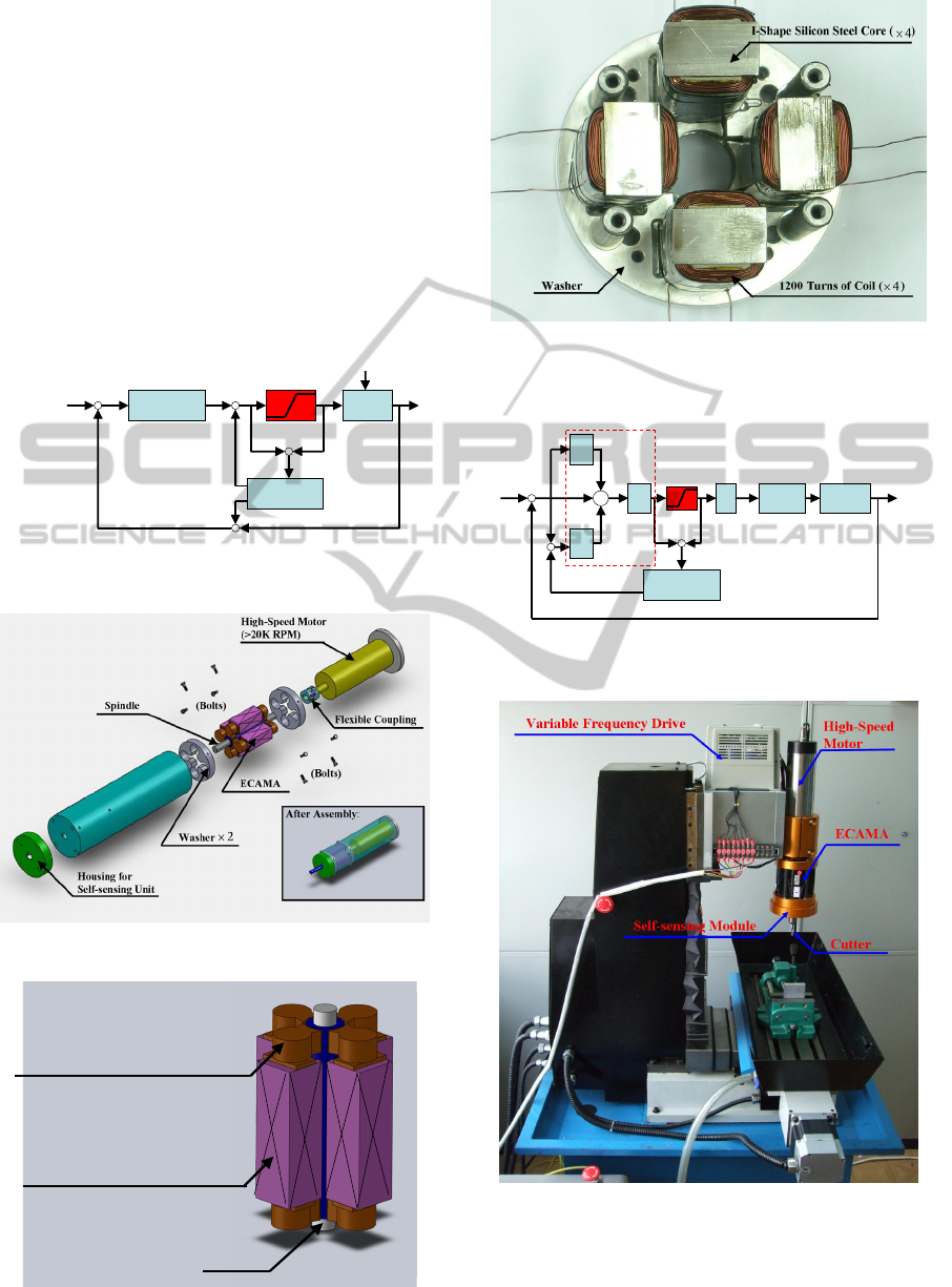
ECAMA is a type of Active Magnetic Bearing
(AMB) and designed for high-speed milling
applications. The proposed ECAMA and the spindle
are depicted in Fig. 2. In addition, a high-speed
motor (>20000 RPM) and a self-sensing module for
spindle position deviation measurement are
equipped at the two ends of spindle. The
configuration of the ECAMA is shown in Fig. 3. It is
mainly composed by the modified concave-type
yokes (Tsai and Hsu, 2007) and the I-shape
electromagnets. The prototype of the I-shape
electromagnets are shown in Fig. 4. Totally 1200
turns of coils are wound around each individual I-
shape silicon steel core.
4 CONTROL STRATEGY FOR
ACTUATOR WINDUP
The unconstrained controller employed in this work
is the PID controller. Owing to the integral action,
the output of controller tends to exceed the upper
limit of power amplifier once a large error exists.
The block diagram of spindle position control
system is shown in Fig. 5. The output of controller is
applied to the coils at ECAMA via power amplifiers.
By tuning the supplied coil current, the spindle
position can be regulated by the induced magnetic
forces. In fact, the AW compensator in Fig. 5 is a
gain. By compensating the input of integral term, the
controller output can be suppressed to be within
unsaturated region. Since the magnetic saturation
against ECAMA is determined by both the supplied
coil current and the area of I-shape silicon steel core,
the actual upper limit of the supplied coil current for
the AW compensator design in this work is
evaluated by experiments. According to the
experimental results (Tsai and Lee, 2010), the upper
and lower ampere-turns limits of coil are found to be
2000 and 0 ampere-turns respectively. Since the coil
wound on each I-shape electromagnet is 1200 turns,
the upper and lower limits of supplied coil current
are 1.67 A and 0 A respectively.
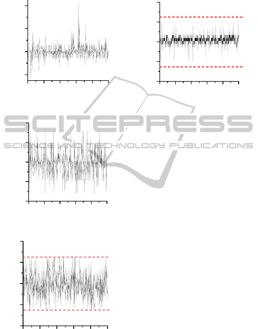
5 EXPERIMENTAL RESULTS
The test rig in our work, including the milling
machine (by How-mau Mchinery CO., LTD, Model
CNC-K3), is depicted in Fig. 6. The original milling
spindle of CNC-K3 is replaced by the proposed
ECAMA. Prior to the experiments, a set of PID
gains which can operate stably under low rotating
speed, i.e., 1000RPM is given. The follow-up
experiments are performed under spindle speed of
6000 RPM. The experimental results in X-axis are
shown in Fig. 7~Fig. 10. Fig. 7 and Fig. 8 are the
outputs of the controller without and with AW
compensation respectively. It is obvious that the
windup phenomenon induces large control outputs,
no matter in positive or negative side. On the
contrary, all the controller outputs are within
,200
±
which is referred to the supplied coil voltage of
V,20
±
under AW compensation. The spindle
position deviations in X-axis without and with AW
compensation are shown in Fig. 9 and Fig. 10. The
dotted lines in Fig. 9 and Fig. 10 are referred to the
maximum spindle position deviation which is
limited by the Auxiliary Bearing (AB) (Tsai, Shih
and Lee, 2010) to avoid collision in case
malfunction of ECAMA occurs. The spindle
position deviation under actuator saturation is shown
in Fig. 9. Drastic tremble of spindle and collision is
observed. However, the spindle position deviation,
shown in Fig. 10, is much improved under AW
compensation and no collision between spindle and
ECAMA/AB bearing takes place. In other words, the
efficacy of the AW compensator for actuator
saturation is verified.
6 CONCLUSIONS
The AW (Anti-Windup) compensator is proposed
and applied to ECAMA (Embedded Cylindrical-
Array Magnetic Actuator) to retain the performance
of spindle position regulation under actuator windup.
According to the experimental results, without any
modification of the PID controller, the controller by
aid of AW compensator can still operate well under
ICINCO 2011 - 8th International Conference on Informatics in Control, Automation and Robotics
196
actuator saturation. However, ECAMA is designed
for high-speed milling. Since the cutting force
between the cutter and workpiece sometimes alters
drastically in a very short period of time during the
practical milling process, the response of ECAMA
might not be able to instantly follow up. That is, an
anti-windup compensation against saturation of
supplied current grow rate is therefore required. The
forthcoming research by the authors will be focused
on this issue.
7 FIGURES
Unconstrained
Controller
r
(Reference)
w
(Disturbance)
Plant
y
c
y
p
u
Anti-Windup
Compensator
y
aw1
y
aw2
++
+
+
+
+
-
-
u
s
Figure 1: Schematic Diagram of Anti-Windup
Compensation.
Figure 2: ECAMA and Spindle for Mill Machine.
Modified Concave-type Yoke ( )
Spindle
I-shape Electromagnet ( )
( I-shape Silicon Steel Core
with Coil Wound )
4×
8×
Figure 3: Configuration of ECAMA.
Figure 4: Prototype of I-shape Electromagnets (Bottom
View).
r
ECAMA
d
(Position)
Anti-Windup
Compensator
+
+
+
-
-
K
p
K
i
/s
K
d
s
-
+
K
PID Controller
Power
Amp.
Spindle
Dynamics
+
+
i
Figure 5: Block Diagram of Spindle Position Control
System.
Figure 6: Test Rig for AW Compensation.
SELF-TUNING ALGORITHM AGAINST MAGNETIC ACTUATOR WIND-UP FOR MILLING SPINDLE POSITION
REGULATION
197
0.00 1.00 2.00 3.00 4.00 5.00
-400.00
0.00
400.00
800.00
Time (Sec.)
Control Signal for ECAMA in X-axis
Figure 7: Controller Output w/o AW Compensation
(Speed: 6000RPM).
0.00 1.00 2.00 3.00 4.00 5.00
-200.00
-100.00
0.00
100.00
200.00
Time (Sec.)
Control Signal for ECAMA in X-axis
Figure 8: Controller Output with AW Compensation
(Speed: 6000RPM).
0.00 1.00 2.00 3.00 4.00 5.00
-0.80
-0.40
0.00
0.40
0.80
Time (Sec.)
Spindle Position Deviation in X-axis (mm)
0.50
-0.50
Figure 9: Spindle Position Deviation w/o AW
Compensation (Speed: 6000RPM).
Time (Sec.)
Spindle Position Deviation in X-axis (mm)
0.00 1.00 2.00 3.00 4.00 5.00
-0.80
-0.40
0.00
0.40
0.80
0.50
-0.50
Figure 10: Spindle Position Deviation with AW
Compensation (Speed: 6000RPM).
REFERENCES
Astrom, K. J., Rundqwist L., 1989. Integrator Windup and
How to Avoid It. In Proceeding American Control
Conference. Pittsburgh, USA.
Tarbouriech, S., Queinnec I., Garcia, G., 2007. Anti-
Windup Strategy for Systems Subject to Actuator and
Sensor Saturations, Chap. 6 in Advanced Strategies in
Control systems with Input and Output Constrains.
LNCIS, Vol. 346, Springer-Verlag.
Tsai, N.-C., Lee, R.-M., 2010. Regulation of Spindle
Position by Magnetic Actuator Array. International
Journal of Advanced Manufacturing Technology. DOI:
10.1007/s00170-010-2830-0.
Tarbouriech, S., Turner, M., 2009. Anti-Windup Design:
An Overview of Some Recent Advances and Open
Problems. IET Control Theory and Applications, Vol.
3, No. 1, pp. 1-19.
Tsai, N.-C., Hsu, S.-L., 2007. On Sandwiched Magnetic
Bearing Design. Electromegnetics, Vol. 27, No. 6, pp.
371-385.
Tsai, N.-C., Shih, L.-W., Lee, R.-M., 2010.
Counterbalance of Cutting Force for Advanced Milling
Operations. Mechanical Systems and Signal Proce-
ssing, Vol. 24, No. 4, pp. 1191-1208.
ICINCO 2011 - 8th International Conference on Informatics in Control, Automation and Robotics
198
