
MOBILE ROBOT LOCALIZATION SCHEME
BASED ON FUSION OF RFID AND VISUAL LANDMARKS
Younes Raoui
1,2,3
, El Houssine Bouyakhf
1
and Michel Devy
2,3
1
Faculty of Sciences, University Mohamed V at Agdal, Rabat, Morocco
2
CNRS; LAAS, 7 avenue du colonel Roche, F-31077 Toulouse Cedex 4, France
3
Universit´e de Toulouse; UPS, INSA, INP, ISAE; UT1, UTM, LAAS, F-31077, Toulouse Cedex 4, France
Keywords:
Mobile Robot, Indoor, Localization, RFID, Vision.
Abstract:
A key function required on an autonomous mobile robot is the ability to localize itself accurately. This paper
reports an RFID and vision-based localization scheme, which uses new rotation and scale invariant features
as natural landmarks in static environments. The invariance of these features to image translation, scaling and
rotation makes them suitable landmarks for mobile robot localization. Our RFID-based localization method
presented in (Duarte et al., 2010) is made active minimizing the information entropy and improving the posi-
tioning accuracy. Then methods based on the detection of a priori learnt RFID tags and visual landmarks are
combined in order to make more robust the method.
1 INTRODUCTION
Mobile navigation can be viewed as the art of correct-
ing the unaccuracy of internal sensors by taking ad-
vantage of exteroceptive sensors like cameras, laser
range finders...Many strategies have been proposed
for robot localization based on interesting objects and
landmarks. Simultaneous Localisation and Mapping
attains a maturity in the last decade, so that environ-
ment models can be acquired before exploiting it only
for robnt localization.
Figure 1: The RACKHAM demonstrator from LAAS(left),
Cartesian Detection Model of every RFID antenna (right).
Sensors like RFID antennas, laser range finders
and cameras have the ability to estimate the egomo-
tion of the robot. These sensors may give complemen-
tary information and may also sometimes be redun-
dant. There are many possible architectures to fuse
sensory data. Mobile robots are generally endowed
with dead reckoning sensors such as wheel encoders
and inertial sensors. All these sensor measurements
can be fused to estimate the robot position by using
filtering methods like Kalman, Particle or Information
filter.
This paper focuses on the self-localization func-
tion, required when the robot has to reach a given ob-
jective with a good accuracy, e.g. at maximum, 20cm.
Two solutions are proposed: the first uses RFID sen-
sor to estimate the robot position from the Monte-
Carlo approach using RFID tags detected by antennas
mounted on the robot. The second one fuses two types
of sensors, RFID reader and an embedded camera.
Thus, we propose a new method for image description
that has been used as landmarks in a monoSLAM al-
gorithm using the Davison approach (Davison and al,
2007).
In the first chapter we present a new image de-
scriptor with an application to object recognition. In
the second chapter we present a method for robot nav-
igation with RFID technology. In the third section we
present our method for navigation based on sensor fu-
sion from RFID and vision.
2 RELATED WORKS
Several recent works in robotic localization are based
either on vision or on RFID technology. An RFID
296
Raoui Y., Houssine Bouyakhf E. and Devy M..
MOBILE ROBOT LOCALIZATION SCHEME BASED ON FUSION OF RFID AND VISUAL LANDMARKS.
DOI: 10.5220/0003533502960299
In Proceedings of the 8th International Conference on Informatics in Control, Automation and Robotics (ICINCO-2011), pages 296-299
ISBN: 978-989-8425-75-1
Copyright
c
2011 SCITEPRESS (Science and Technology Publications, Lda.)
based method close to ours is presented in (Hahnel
and al, 2005); they also used a probabilistic sensor
model for their RFID reader; they associate the prob-
ability of tag detection with the relative position of
their tag. This model is used to map positions of pas-
sive RFID tags, considering the robot is located from
a previously learnt map through laser based SLAM.
Vorst and al (Vorst and Zell, 2010) have developped
a method of localisation on which the estimation is
based only on odometry and RFID measurements.
The technique requires no prior observation model
and makes no assumptions on the RFID setup. On the
other hand, using vision based approach, Zhou and
al (Zhou and al, 2007) proposed an indoor localization
method with modified active RFID tags, equipped
with LEDs which make the recognition much easier.
In (Ziparo and al, 2007), RFID tags are detected to
coordinate a team of robots for an exploration in un-
structured areas. In (Raoui and al, 2009), two strate-
gies are presented for metrical and topological navi-
gation with tags merged on shelves and on the ground.
Other researchers use vision based localization, but
the work of (Davison and al, 2007) is considered as a
turning point in the monoSLAM based navigation.
The fusion of many types of sensor data makes
more accurate the robot position. In (Deyle and
al, 2009), an RFID-enabled mobile manipulator can
grasp an object to which a self-adhesivepassive RFID
tag has been fixed; this new mode of perception pro-
duces a map of the spatial distribution of received sig-
nal strength indication for each of the tagged objects
in an environment.
3 GENERATING FEATURES
Our visual features (Raoui and al, 2009) are based on
the Harris detector because of its suitability in com-
putation time. We extend it to the colored images
by using the Gaussian color model(Geusebroek and
al, 2001). It is based on the second moment matrix
also called the auto correlation matrix. The detector
is made invariant to scale computing four characteris-
tic scales aroud each feature point, by the use of the
LoG operator (K.Mikolajzyk and C.Schmid, 2004).
The orientation for interest points is computed as
in (Lowe, 2004). It has good performances compar-
ing to other descriptors because it mixes localized in-
formation and the distribution of gradient related fea-
tures. Thus, for each scale the image is processed
to extract the orientation for the feature point and all
points around it ( 4 points). We concatenate these ori-
entations in the same descriptor. Then, we compute
the descriptor around each feature point (figure 2) by
Algorithm 1
1: for i← Feature Point-2 to Feature Point+2 do
2: box ← Create a box around a point i
3: result ← box * Gaussians(scales)
4: Compute norm(result)
5: V ← 4 highest values
6: Add V to the Feature Point
7: end for
using a set of 9 Gabor wavelets (Gabor, 1946). In or-
der to evaluate our detector and descriptor, we use the
repeatability score as suggested in (K.Mikolajzyk and
C.Schmid, 2004); a comparison is shown on figure 3.
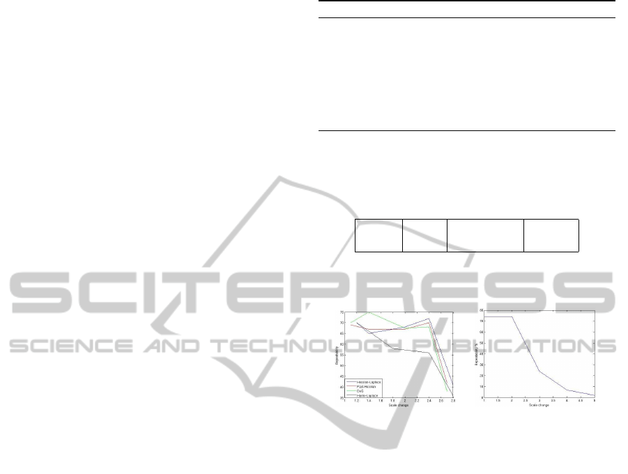
x y σ r t
space scale orientation texture
Figure 2: Structure of our descriptor, 2 bin for space, 21 for
scale, 5 for orientation, 9 for texture.
Figure 3: Repeatability of Fast Hessian, DoG, Harris-
Laplace, Hessian-Laplace interest points detectors with re-
spect to scale(left).Repeatabilty of our detector descriptor
with respect to scale(right).
4 RFID-BASED ROBOT
LOCALIZATION
Our method for stochastic localization from RFID
Tags, is presented in (Duarte et al., 2010); it is based
on a particle filter in order to estimate the robot pose
from RFID observations. Such a filter represents the
state at step k by a random vector x
k
. Then a proba-
bility distribution over the position and orientation of
the robot x
k
, known as belief, Bel(x
k
) represents the
uncertainty of the state. In the particle filter scheme,
the belief function is represented by a set of n pairs
< x
k
i
,w
k
i
> defined by a position x and a weight w.
This weight is a measure of how much its related posi-
tion x represents the real robot position with respect to
the environment model. A function p(x
k
|x
k1
), known
as prediction function, and a correction function of w
k
must be defined. p(x
k
|x
k1
) models the dynamic of the
moving object, using here the odometry model. w
k
is
corrected depending on how much the actually sensed
data fit the position x
k
.
In order to maximize localization performances,
MOBILE ROBOT LOCALIZATION SCHEME BASED ON FUSION OF RFID AND VISUAL LANDMARKS
297

we apply an active control strategy, coupling control
actions into the estimation process. Then, an infor-
mation theoretic control is used. In fact, information
measures quantify the uncertainty in a probabilisti-
cally representation estimation and are used as cost
functions for potential control actions. Thus, the in-
formation metric is defined as a function of probabil-
ity distribution.
I[x] = f[p(x)]
where p(x) represents the estimates of the robot
positions [x y], which is considered as a gaussian with
a mean hat(x) and a covariance P. The information
metric is h(x) =
1
2
log[(2πe)
n
|P|]. The information
gain is defined as the difference in the information of
our estimation before and after a particular action.
I[x,a] = h[p(x/a)] − h[p(x)]
While the vehicle moves it follows the follow-
ing procedure: (1) choose a trajectory that maximizes
I[x,a], (2) propose several trajectories and (3) estimate
the observation based on the antenna reception field
that will be made along each trajectory
Algorithm 2: Algorithm ActiveMCL(X
t−1
, u
t
, z
t
, m).
1: X
t
← 0
2: for m ← 1 to M do
3: for i ← 1 to I do
4: x
m
t,i
← sampleMotionMmodel(u
t,i
,x
m
t−1
)
5: w
m
t,i
← measurementModel(z
t
,x
m
t
,m)
6: X
t,i
← X
t,i
+ < x
m
t,i
, w
m
t,i
>
7: end for
8: end for
9: for i ← 1 to I do
10: x
t,i
= mean(x
m
t,i
)
11: x
t−1,i
= mean(x
m
t−1,i
)
12: L(i) ← entropy(x
t,i
)-entropy(x
t−1,i
)
13: end for
14: i
max
← max(L)
15: xa
t
← x
t,i
max
16: for m ← 1 to M do
17: draw i with probability w
i
t
18: add xa
i
t
to Xa
t
19: end for
20: return Xa
t
Line (4) in our algorithm create samples from
present belief as starting point. The perception model
of RFID antennas is then applied as indicated in line
(5) to determine the importance weight of each par-
ticle. In line (3) we make an iteration over all possi-
ble actions from t to t+1. So we have possible poste-
rior positions x
m
t,i
and weights w
m
t,i
. The initial belief
bel(x
0
) is obtained by randomly generating M such
Figure 4: Robot localization at different positions with the
computation of standard deviation for x,y,θ
particles from the prior distribution p(x
0
, and assign-
ing the uniform importance function M
−1
to each par-
ticle. For each action i, we compute the difference in
the entropy between the mean of the particles at time t
and t+1. In line 12, we look for the index of the action
that maximizes L(i).
5 FUSION OF RFID AND IMAGE
DATA
An efficient method for localization fuses signal de-
tection from RFID tags and for fine localization, it
incorporates visual landmarks detection, using image
descriptors presented in section 1. In order to com-
pute the camera motion, we use an angular contraint, a
linear velocity model and odometry model. The state
vector is expressed with x
v
=
r
WC
q
WC
v
W
W
w
, where
r
WC
is the position of the camera optical center, q
WC
is the quaternion that defines orientation, v
W
and W
w
are the linear and angular velocities.
At every step, we compute the next step by us-
ing the odometry model P(x
t
/x
t−1
,u) and an angular
acceleration zero mean Gaussian process a
W
and α
w
,
which produces an impulse of linear and angular ve-
locity. Thus,
n =
V
W
ω
W
=
a
W
δ(t)
α
W
δ(t)
+ P(r
WC
t
/r
WC
t−1
,u) (1)
Let us suppose that a set of euclidean points have
been previously learnt by a bearing-only approach.
We compute the predicted position of a point feature
relative to the camera with estimates, x
v
of camera
position and y
i
of feature position. the camera is ex-
pected to be: h
R
L
= R
RW
(y
W
i
− r
W
)
With a perspective camera, the position (u v) at
which the feature would be expected to be found in
the image is found using the standard pinhole model:
u = − fk
u
h
x
h
z
+ u
0
; v = − fk
v
h
y
h
z
+ u
0
, where f
ku
, f
kv
,
u
0
and v
0
are the standard camera calibration param-
eters. The state update produced is given with:
f
v
=
r
w
new
q
WR
new
v
W
new
ω
W
new
=
r
w
+ (v
w
+V
w
)δ
t
q
WR
∗ q((ω
W
+ Ω
W
))δ
t
v
W
+V
W
ω
W
+ Ω
W
ICINCO 2011 - 8th International Conference on Informatics in Control, Automation and Robotics
298

EKF updates the robot state by fusing odometry
and vision data. The estimate of the new state is
f
v
(x
v
,u) and the state uncertainty Q
v
for the camera
are estimated after each motion or observation. We
would therefore like to improve the odometry esti-
mate of the ego-motionby matching the extracted fea-
tures between frames. Once the features are matched,
we can then use the matches in a least-squares proce-
dure to compute a more accurate camera ego-motion
and hence better localization. A match between two
descriptors is accepted only if distance is less than 5
times the distance to the second closest match.
We simulate an environment by taking a sequence
of colored images from an office room where we have
distributed RFID tags. In order to localize itself, the
robot uses both these tags and captured images. If it
succeeds in detecting tags, which obey to the sensor
model described in the figure (1), it apply the method
described in section 2. At the same time, it captures
an image with its camera. If no tag is detected, it
extracts our developped feature points and computes
their descriptors. It will then match these image fea-
tures with the memorized ones. The robot will use
them to compute its current position. This strategy al-
lows the robot to acquire data from the environment
at each time. The algorithm 3 explains our method.
Algorithm 3
1: for i ← 1 to NumberO fImages do
2: CaptureImage()
3: pos(i) ← addNewFeature(i)
4: match (pos(i),pos(i-1))
5: [x
i/i−1
, p
i/i−1
]=EKF Prediction(x
i−1
, p
i−1
)
6: add pos(i) to x
i/i−1
(The state vector)
7: Get Odometry
8: [z
i
]=Get measurement
9: H
i
=dataAssociation(x
i/i−1
,z
i
)
10: [x
i
, p
i
]=EKF Update (x
i
, p
i
,z
i
,H
i
)
11: end for
6 CONCLUSIONS
This paper proposes first the computation of interest
point descriptor for colored images which is invariant
to scale and rotation. Then we have developped a lo-
calization method based RFID sensor readings. The
integration of both measurements permits to localize
a mobile robot with a bounded error estimation, and
with a better robustness.
Figure 5: Predicted positions of the robot (top left), po-
sitions estimated from visual landmarks (top right), posi-
tions estimated friom RFID tags (bottom left), positions es-
timated from the fusion (bottom right).
REFERENCES
Davison, A. and al (2007). Monoslam: Real-time single
camera slam. IEEE Trans. on Pattern Analysis and
Machine Intelligence (PAMI).
Deyle, T. and al (2009). Rf vision: Rfid receive signal
strength indicator (rssi) images for sensor fusion and
mobile manipulation. In Proc. Int. Conf. on Intelligent
Robots and Systems (IROS).
Duarte, A. C., Devy, M., and Lemaire, C. (2010). Robot
localization algorithm using odometry and rfid tech-
nology. In Proc. Int. Symp. on Intelligent Autonomous
Vehicles (IAV).
Gabor, D. (1946). Theory of communication. Journal I.E.E.
Geusebroek, J. M. and al (2001). Color invariance. IEEE
Trans. on Pattern Analysis And Machine Intelligence
(PAMI).
Hahnel, D. and al (2005). Mapping and localization with
rfid technology. Proc. Int. Conf. Robotics and Au-
tomation (ICRA).
K.Mikolajzyk and C.Schmid (2004). Scale & affine invari-
ant interest point detectors. Int. Journal of Computer
Vision (IJCV).
Lowe, D. (2004). Distinctive image features from scale-
invariant keypoints. Int. Journal of Computer Vision
(IJCV).
Raoui, Y. and al (2009). Rfid-based topological and metrical
self-localization in a structured environment,. In Proc.
Int. Conf. on Advanced Robotics (ICAR).
Vorst, P. and Zell, A. (2010). Fully autonomous trajectory
estimation with long-range passive rfid. In Proc. IEEE
Int. Conf. on Robotics and Automation (ICRA).
Zhou, Y. and al (2007). Laser-activated rfid-based indoor
localization system for mobile robots. In Proc. Euro-
pean Conf. on Mobile Robotics (ECMR).
Ziparo, V. and al (2007). Cooperative exploration for usar
robots with indirect communication. In Proc. Int.
Symp. on Intelligent Autonomous Vehicles (IAV).
MOBILE ROBOT LOCALIZATION SCHEME BASED ON FUSION OF RFID AND VISUAL LANDMARKS
299
