
BEAM TRAJECTORY CONTROL OF THE FUTURE COMPACT
LINEAR COLLIDER
G. Balik
LAPP, Université de Savoie, CNRS/IN2P3, Annecy-le-Vieux, France
A. Badel
3
, B. Bolzon
2
, L. Brunetti
1
, B. Caron
3
, G. Deleglise
1
, A. Jeremie
1
R. Le Breton
3
, J. Lottin
3
, L. Pacquet
1
1
LAPP, Université de Savoie, CNRS/IN2P3, Annecy-le-Vieux, France
2
CERN-European Organization for Nuclear Research, Geneva, Switzerland
3
SYMME-Polytech Annecy Chambéry, Université de Savoie, Annecy-le-Vieux, France
Keywords: Adaptive algorithm, Disturbance rejection, Least-squares algorithm, Optical feedback, Parameter
optimization, Vibration control.
Abstract: The future Compact Linear Collider (CLIC) currently under design at CERN (European Organization for
Nuclear Research) would create high-energy particle collisions between electrons and positrons, and
provide a tool for scientists to address many of the most compelling questions about the fundamental nature
of matter, energy, space and time. In accelerating structure, it is well-established that vibrations generated
by the ground motion constitute the main limiting factors for reaching the luminosity of 10
34
cm
-2
s
-1
. Several
methods have been proposed to counteract this phenomena and active vibration controls based on the
integration of mechatronic systems into the machine structure is probably one of the most promising. This
paper studies the strategy of the vibration suppression. Active vibration control methods, such as optimized
parameter of a numerical compensator, adaptive algorithm with real time control are investigated and
implemented in the simulation layout. The requirement couldn’t be achieved without the study of active-
passive isolation able to damp high frequency ground motion. Thus, a pattern of a potential active/passive
isolation has been proposed opening up prospects on the design of a future mechanical isolation.
1 INTRODUCTION
After the world’s largest particle accelerator LHC
(Virdee, T. S., 2010, The LHC project), the next
generation of accelerators is being designed. Among
them, the Compact Linear Collider CLIC is an
ambitious project that proposes colliding beams of
positrons and electrons.
The performance requirements of CLIC
challenge the stabilization and control system in a
number of areas. In order to achieve the required
luminosity of 10
34
cm
-2
s
-1
, two beams are accelerated
and steered into collision. Considering the desired
size of the beams (nanometer scale), the collision
will require a very low vertical motion of these two
beams all along the collider, and more specially
through the last two focusing magnets. This can be
done only by focusing and colliding the two separate
beams to nanometer spot sizes. Thus, it imposes
very tight constraints on the final focus (FF)
system’s alignment and stability.
The future CLIC composed of two arms of
approximately 17 km long facing each other will
accelerate beams at velocities near the speed of light.
Once accelerated with the required energy and
emittance (Assmann, R. W. et al., 28 July 2000)
through the main linac, a sophisticated beam
delivery system focuses the beam down to
dimensions of 1 nm RMS size in the vertical plane
and 40 nm horizontally. This requires the final focus
magnets to be stabilized to vibration amplitude of
less than 0.1 nm for oscillations above 0.1 Hz at the
interaction point (IP).
Given the tight specifications and hardware
limitations, ground motion mitigation is a real
challenge. This paper proposes a method to deal
with ground vibrations. A first part aims to design a
97
Balik G., Badel A., Bolzon B., Brunetti L., Caron B., Deleglise G., Jeremie A., Le Breton R., Lottin J. and Pacquet L..
BEAM TRAJECTORY CONTROL OF THE FUTURE COMPACT LINEAR COLLIDER.
DOI: 10.5220/0003534700970104
In Proceedings of the 8th International Conference on Informatics in Control, Automation and Robotics (ICINCO-2011), pages 97-104
ISBN: 978-989-8425-74-4
Copyright
c
2011 SCITEPRESS (Science and Technology Publications, Lda.)
filtering algorithm combining feedback control and
real time adaptive algorithm based on the
generalized least square algorithm. Next a study of
the global pattern of the isolation needed to achieve
the requirements is presented. This paper ends up
with numerical simulations and robustness test.
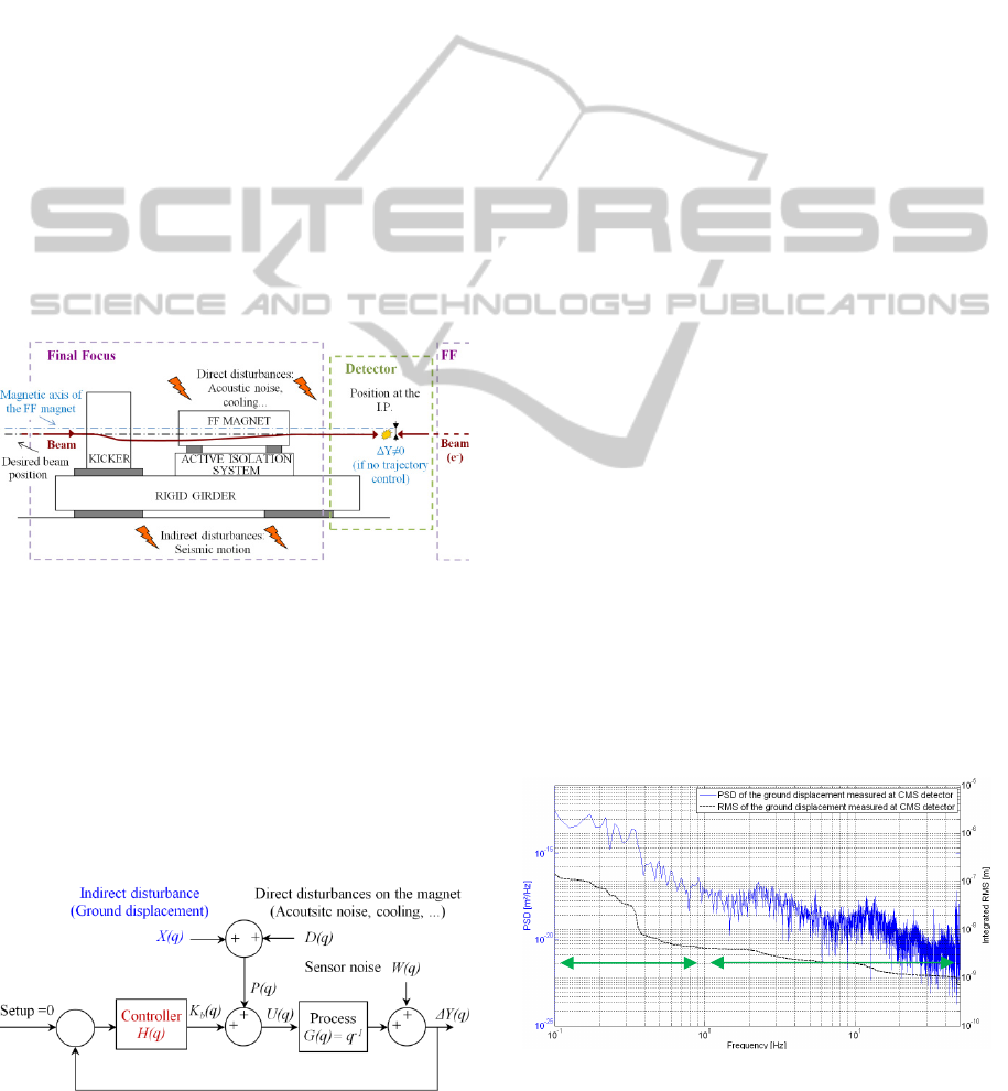
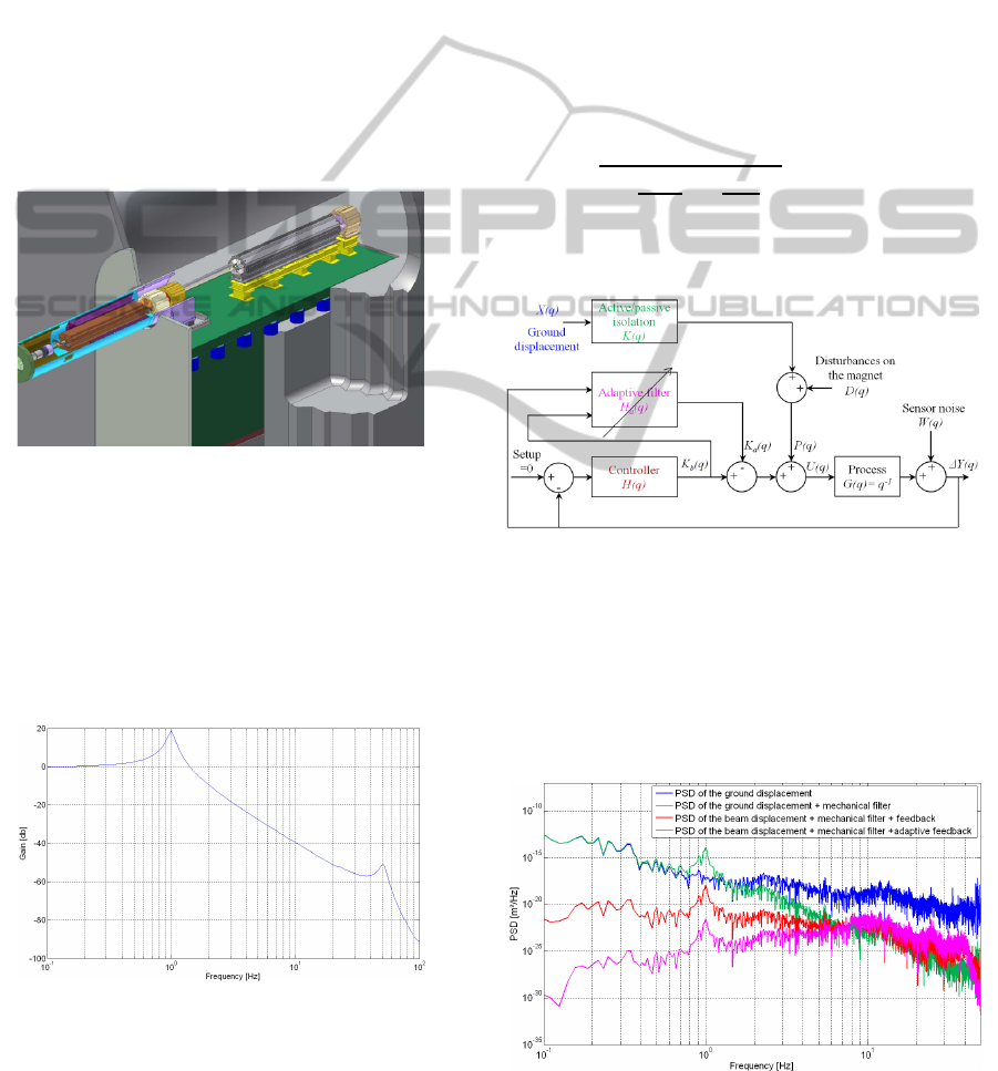
2 BEAM-BASED FEEDBACK
Once accelerated, the beam goes through a final
focusing magnet subject to disturbances (see fig. 1)
Stabilization of the beam can be obtained by using
the corrective capabilities of the beam components
by measuring the beam parameters (size, position…)
tanks to a Beam Position Monitor (BPM) (not
represented) and acting on the beam with a kicker.
The frequency range in which this is possible is
given by the beam repetition rate. For CLIC, this
rate is 50Hz (which means that the beam is
composed of a serial of trains separated from each
other in time by 20 ms). This configuration imposes
that the beam cannot be corrected above several Hz.
Figure 1: Final focus scheme.
As ground motion is still at a detrimental level
until about 50-100Hz, depending on the site, it needs
to be corrected by mechanical means. Thus, this
magnet stands on an active-passive support designed
to reduce ground motion vibrations.
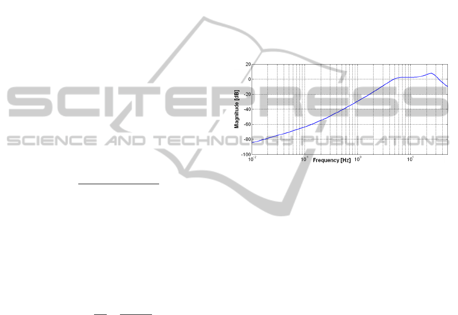
The proposed control framework is composed of
a feedback loop where the controller (H) defines the
dynamical behaviour of the system. The structure of
this control is given in figure 2 (The backward shift
operator is denoted q
-1
).
Figure 2: Scheme of the beam trajectory control.
The disturbance (X) is the mechanical excitation
from ground motion (see part 2.1) which is also the
disturbance felt by the magnets (Other sources of
disturbances are neglected as their contribution to
the beam motion is supposed to be insignificant
compared to the ground motion itself). (P) is finally
the disturbance felt by the magnet.
The transfer function between the mechanical
displacement of this magnet and the beam can be
modeled by a constant matrix (equal to 1 in the
model as it is considered as a uniform rigid
structure). Finally the noise of the sensor (W) is
added to the displacement of the beam.
The action (K
b
) meant to reduce the motion of
the beam (or the offset between the two beams at the
interaction point) is done by a kicker. The obtained
displacement of the beam is proportional (equal to 1
in the following model) to the injected current of the
kicker. The dynamic of the system is due to the
frequency of the beam train, so the process can be
treated as a first approach as a delay at a sampling
period equal to 0.02 s.
This scheme allows to design a controller (H)
that performs optimally (depending on the PSD of
the ground motion) to minimize the integrated RMS
displacement of the beam.
2.1 The Ground Motion
For this study, the reference is the measured motion
in the tunnel of the Large Hadron (LHC) at CERN
and more precisely, the ground motion where is
located the Compact Muon Solenoid (CMS)
calorimeter (The CMS Collaboration, 2008). Figure
3 represents the PSD and the integrated RMS of the
ground motion measured at CMS thanks to a
geophone (Güralp CMG-6T calibration: ±12.5 mm
s-1, Frequency range: [0.033-50] Hz, sensitivity:
2x998 V s m
-1
, resolution: 0.05 nm between 4 Hz
and 50 Hz) (Güralp Systems Limited, Inc.)
Figure 3: PSD and integrated RMS of the ground motion
measured at CMS.
Cultural
noise
Earth
motion
ICINCO 2011 - 8th International Conference on Informatics in Control, Automation and Robotics
98
Considering the limited bandwidth of the
geophones, simulations have been computed in the
frequency range [0.1-50] Hz instead of [0-∞[. Note
that the limitation at 50 Hz has no impact on the
results as the PSD decreases significantly with
frequency above this frequency.
The PSD of the natural ground motion is a steep
function of frequency which falls off as 1/f
4
. Several
peaks can be observed, related to machinery and
structural resonances. Such peaks appear as steps in
the integrated R.M.S. PSD is particularly useful,
because it allows to calculate the total RMS (Root
Mean Square) displacement in any frequency band
(or indeed over the whole frequency range
measured) by integrating the displacement PSD and
taking the square root.
2.2 Design of a Classical Controller
The required specifications impose to lower the
integrated RMS(0). The controller has to provide
real-time computation. Considering the process and
the previous requirements, the structure of the
controller has been chosen to be the following:
(
)
=
+
+
1+
+
Higher order structures of the controller have
been tested but it didn't result in a significant gain
compared to the complexity of the feedback control.
Considering the previous scheme (fig.2), the closed
loop transfer function taken into account is the
transfer function between the beam displacement
and the disturbance X (also called sensitivity transfer
function):
(
)
=
Δ
X
=
1+
Note that as G is a pure delay, the effect, in term
of amplitude of the closed loop on sensor's noise
disturbance W (or any direct disturbance D) is the
same as for the ground motion disturbance P.
2.3 Optimization of the Controller
The method to lower the RMS(0.1Hz) of is the
following:
• Estimation of the PSD of the measured ground
motion signal,
• Scanning the parameter space of the controller,
• For each of these combinations, if the parame-
ters give a stable closed loop transfer function
F, then:
• Computation of the PSD of the obtained output
using:
•
(
)
=
|
(
)|
.(
(
)
)
• Computation of the integrated RMS ,
• Selection of the parameters' set of the
controller that gives the minimum RMS (0).
As these parameters obviously depend on the
PSD of the input disturbance (P), if this signal is
changed in terms of PSD, then the optimization will
produce another set of parameters.
The transfer function F between the ground
motion disturbance and the output depends
obviously on these parameters. In the optimized
case, the next plot represents its transfer function:
Figure 5: Sensitivity transfer function magnitude.
However, the sensitivity transfer function F has
an important property:
|
()
|
= 0
/
with
=2
This formula obtained from Bode's sensitivity
integral (Mohtadi, C., 1990, Bode's integral theorem
for discrete-time systems) induces that lowering
effects of disturbances at low frequencies will
increase effects of disturbances at high frequencies
(also called “water bed effect”).
2.4 Simulation Results
The following simulation has been computed by
injecting a sample of the ground motion disturbance.
No other noise has been considered. Figures 5 and 6
represent the PSD and the integrated RMS
displacements obtained by simulation with the
optimized feedback control loop:
BEAM TRAJECTORY CONTROL OF THE FUTURE COMPACT LINEAR COLLIDER
99
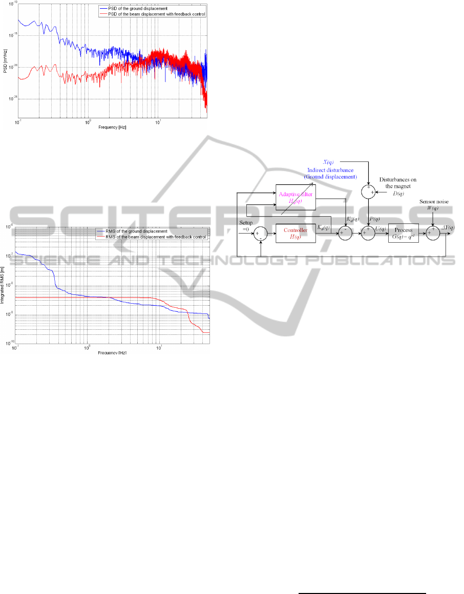
Figure 5: PSD obtained with feedback control.
The plot above shows mainly two things; first of
all, the controller is able to correct the beam
trajectory to compensate effect of ground motion
between [0-6] Hz. Then after 5-6 Hz, it will increase
ground motion.
Figure 6: Integrated RMS obtained with feedback control.
This amplification after 6 Hz has bad
consequences for the integrated RMS which rises to
almost 4 nm.
Because of the sample time of the process, the
feedback is efficient in a very limited frequency
bandwidth [0-5] Hz. It implies that the integrated
RMS at 5 Hz of the disturbance P has to be the
lowest possible, and that one cannot do better than
this value by the means of a feedback control. It is
thus necessary to consider a complementary solution
able to filter the ground motion vibrations as much
as possible. This study will be the topic of part 4.
3 FEEDBACK AND ADAPTIVE
ALGORITHM STRATEGY
This strategy is most likely used when the sources of
disturbances are unknown or variable in time, which
is the case in this study. The dynamical behavior of
the system is defined by the feedback loop, and an
adaptive algorithm changes the command of the
process to minimize the prediction error. The
ordinary least-squares method may lead to biased or
non-consistent estimates of system parameters in the
presence of noise. The bias problem may be solved,
for example, by using the generalized least-squares
method. In the generalized least-squares method, a
digital filter is used to filter the observed input-
output data.
3.1 Design of the Adaptive Filter
The control scheme is the following:
Figure 7: Adaptive feedback control scheme.
This control uses the prediction-error to
reconstruct and cancel out the disturbance. This
scheme is by nature non-linear as it is composed of
two interlinked loops. To avoid such a complex
study, a general adaptive command structure defined
by Landau's stability theorem (Landau, I. D., Zito,
G., 2006, Digital Control Systems) has been used. In
practice the estimation scheme is needed to be
iterative, allowing the estimated model to be updated
at each sample interval as new data become
available. The generalized least square algorithm
estimates the parameters h of the filter H
a
by
minimizing the following least square criteria:
(
)
=
()
²
This Algorithm uses the prediction error:
(
)
=
(
)
−
(
)
(
−1
)
(balanced with a forgetting factor λ) made on the
estimation to compute the next set of the parameters:
ℎ
(
)
=ℎ
(
−1
)
+
(
)
(
)
using the Kalman gain:
(
)
=
(
−1
)
()
1+
(
)
(
−1
)
()
and the Ricatti equation:
(
)
=
(
−1
)
−λ
(
)
(
)
(
−1
)
ICINCO 2011 - 8th International Conference on Informatics in Control, Automation and Robotics
100
3.2 Simulation Results
Figure 8 and 9 show the obtained performance using
this configuration.
Figure 8: PSD obtained with adaptive feedback control.
The PSD plot shows that this adaptive scheme
has allowed to considerably decrease the power of
the ground motion displacement in the bandwidth
[0-5] Hz. It also has the drawback to increase the
amplification after 5 Hz leading to an integrated
RMS worse than with feedback only.
Figure 9: Integrated RMS obtained with feedback and
adaptive control.
Previous observations with optimized feedback
and adaptive control show that the residual
integrated RMS displacement at 0.1 Hz of the beam
displacement is mainly due to the integrated RMS at
5 Hz of the motion of the magnet support. Above
that frequency, the control is not efficient. The
strategy consists in adding active/passive isolation
under the magnet which steers the beam. It has to
attenuate the ground motion vibration from 5 Hz
which means that the resonance frequency of this
mechanical structure has to be below 5 Hz. Similar
concepts have already been developed in the
research and industrial field (Braccini, S. et al.,
2005), (Ellison, J. et al., 2001, Passive vibration
control of airborne equipment using a circular steel
ring).
4 ACTIVE/PASSIVE ISOLATION
To avoid luminosity loss the vertical position of the
magnets must be stabilized to 0.1 nm RMS for
frequencies of 0.1 Hz and above. This will be
achieved by the previous adaptive feedback
controller and a passive pre-isolator, complemented
by an active isolation system. The characteristic of
this whole isolation system is determined by
simulation in the next part.
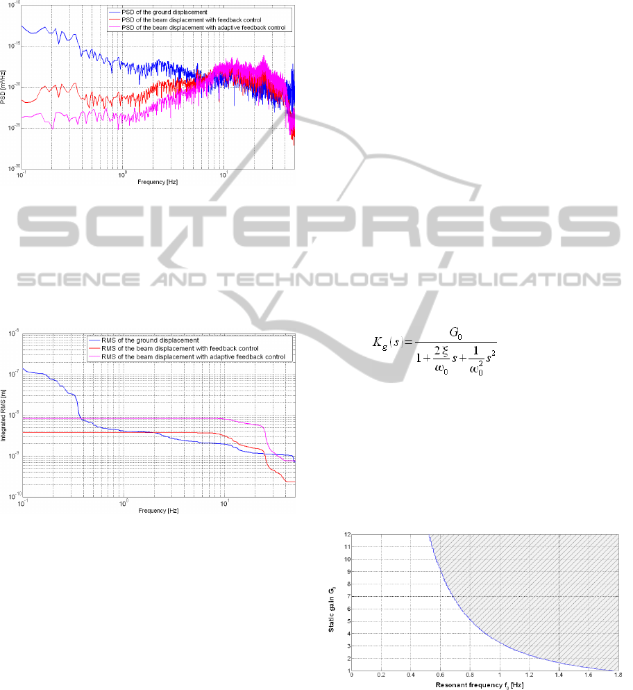
4.1 Pattern of the Mechanical Support
This part aims to establish a pattern of the
mechanical support needed between the ground and
the beam to reach the specifications of 0.1 nm. This
transfer function should be representative of a
typical mechanical support dynamical behavior.
Thus, it has been modeled by the following 2
nd
order
low-pass filter:
with ω
0
=2πf
0
This scheme implied to optimize the controller
for each combination (f
0
, G
0
), until an eventual
solution allows to reach the specifications (The
mechanical filter modification imply a modification
of the input disturbance (P) and a re-optimization of
the controller, see part 3.2). The body of the
combinations (f
0
, G
0
), see figure 10, constitutes the
pattern of the desired active-passive isolation
dynamic.
Figure 10: Pattern of the active-passive isolation dynamic.
The area under the curve represents the body of
the combinations (f
0
, G
0
). The simulation showed
that this pattern is independent of the damping ratio
ξ in the range [0.005 0.7]. This results from the
BEAM TRAJECTORY CONTROL OF THE FUTURE COMPACT LINEAR COLLIDER
101
extremely high efficiency of the adaptive feedback
control in low frequencies.
This pattern is actually used for a more detailed
study of a mechanical support design. This support
will be efficient enough to achieve the desired
performances.
4.2 Passive Isolation
The ground micro-seismic motion at frequencies
above 4 Hz, either natural or generated by
machinery, can be effectively reduced by a passive
mechanical low-pass filter currently being designed
(Ramos, F., Dynamic analysis of the FF magnets
pre-isolator and support system). In this scheme, the
whole system sits on a big massive support; the pre-
isolator:
Figure 11: Layout of the pre-isolator, with the concrete
mass supporting the two final focus magnets.
The two magnets are supported by rigid girders
that are fixed on top of a massive concrete block,
weighing about 80 tons and resting on several
springs (in blue in Figure 11) whose rigidity is tuned
in order to have a vertical resonance of the whole
assembly at 1 Hz. The transfer function of this
mechanical filter is given figure 12:
Figure 12: Transfer function of the pre-isolator.
Ground motions at frequencies above 1 Hz are
reduced by a factor f
2
up to the first internal resonant
mode, which can be tuned to be in the bandwidth 30
– 50 Hz. The system is designed to provide a
reduction of the RMS vertical displacement from
about 3 to 0.1 nm at 4 Hz and it has to work in
combination with the active stabilization (i.e.
adaptive feedback control plus an eventual
combination with an active/passive isolation).
4.3 Mechanical Support Consideration
The study of the design of such an active support is
not the topic of this paper. Its behavior (described
part 4.2) has been modelised by a product of two
second-order low-pass filters (K
1
and K
2
, K=K
1
.K
2
)
with resonance frequencies f
1
= 1 Hz and f
2
= 50 Hz
and damping ratios ξ
1
= 0.05 and ξ
2
= 0.075.
,
(
)
=
1
1+
2
,
,
+
1
,
²
with
=2
This dynamic has been implemented in the next
simulations (see figure 13)
Figure 13: Feedback and adaptive control scheme with
active/passive isolation simulation.
4.4 Results
The following plots represent the simulation results
of the feedback and adaptive control obtained when
filtering the ground motion by the pre-isolator’s
transfer function.
Figure 14: PSD obtained with adaptive feedback control
and mechanical filter.
ICINCO 2011 - 8th International Conference on Informatics in Control, Automation and Robotics
102
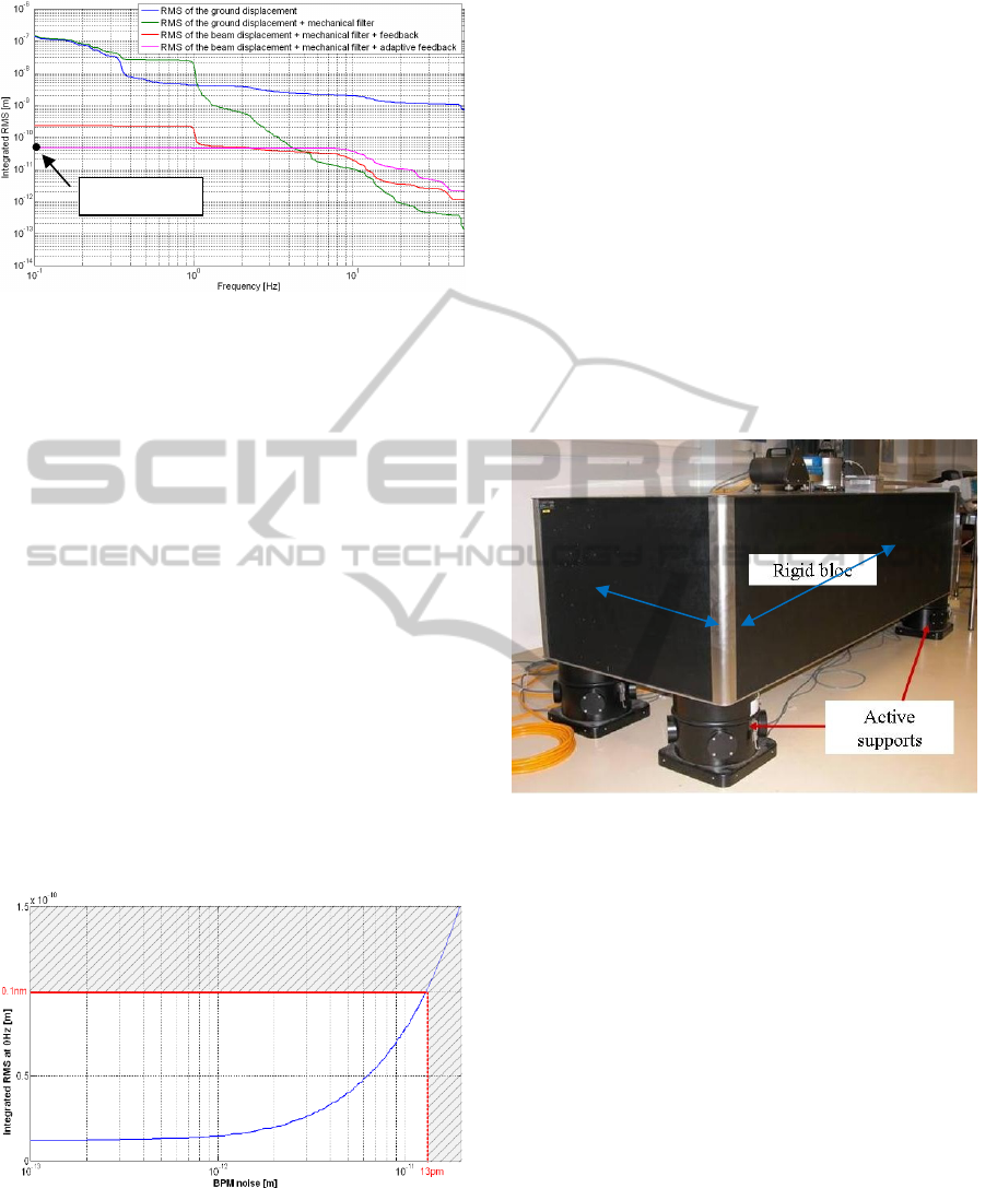
Figure 15: Integrated RMS obtained with adaptive
feedback control and pre-isolator.
The simulation shows that this strategy
combining passive isolation to damp fast motion of
the ground and feedback loop coupled with an
adaptive algorithm which deals with slower motions
is able to reach an integrated RMS at 0.1 Hz of
4.60e
-11
m.
The previous study is based on a model of the
real system currently under development.
Considering the current project status, it was thus
necessary to make several assumptions and to
arbitrarily fix certain parameters.
4.5 Robustness
The goal here was to observe the influence of the
sensor’s noise on the control’s behavior. Figure 16
shows the variation of the integrated RMS
displacement of the beam versus the noise of the
BPM (represented by a white noise (W) added to the
measured displacement).
Figure 16: Variation of the integrated RMS displacement
at 0.1 Hz versus BPM noise.
The level of sensor’s noise is crucial for a good
performance of the control. It cannot exceed 13 pm
integrated at 0.1 Hz to respect the specifications. As
the BPM gives an indirect measurement (amplified
image of the position by 10
5
), the BPM’s noise has
to be < 1.3 µm integrated RMS @ 0.1 Hz. This
result has to be taken into consideration in the design
of this monitor and will certainly be one of the
strategic requirements.
4.6 Perspective
Previous results could even be improved by
combining the previous passive isolation with active
isolation systems. A study of the different
commercial solutions (Redaelli, S., 2003, Thesis)
aimed to select the most efficient one on the market
for this type of application. The selected solution is a
TMC table with STACIS feet (TMC Company,
2002), also described in (Geffroy, N. et al,
Mechatronics 2008), see figure 17:
Figure 17: TMC table with STACIS feet.
This product is able to manage vibrations at a
sub nanometer scale. However, given the tight
tolerances, and the cost of such a product, a
dedicated solution is being developed. This system
includes four piezoelectric actuators and four
capacitive sensors. Such a system is potentially
suitable to be handled by three degrees of freedom
algorithm controlling the vertical motion and the two
associated rotations.
5 CONCLUSIONS
In this paper we have presented our methodology of
the stabilization of the future Compact Linear
Collider. Considering that the imposed tolerances
(integrated RMS (0.1) at the interaction point has to
be lower than 0.1 nm) are considerably lower than
the natural ground motion (a few micrometers),
these requirements are very challenging and were
4.60e
-11
m
2,50
m
1
m
BEAM TRAJECTORY CONTROL OF THE FUTURE COMPACT LINEAR COLLIDER
103

never achieved in the past. This article has
represented a mechanical setup and a dedicated
control approach which allows to obtain a very low
vertical displacement of the beam at the interaction
point of about an integrated RMS (0.1) of 0.046 nm.
In order to perform these results, the strategy was to
carry out a study on an innovative control which is
very efficient in low frequencies. This algorithm is
composed of a combination of a feedback obtained
thanks to a parametric study and an adaptive control
based on the generalized least-squares method. This
method was tested in simulation with a
representative model of the system and with real
measurement of the ground motion. Next, a pattern
of the dynamic of the required mechanical damping
structure, needed to filter the vibrations above a few
Hertz has been established for the purpose of a
further development. To validate this study,
simulation test with a mechanical support have been
performed, and robustness tests as well in order to
take into account the prediction errors of the
mechanical system model and to estimate the
acceptable maximal sensor noise. The study opens
up perspectives for the construction of an active-
passive isolation support as well. Thus, a massive
support is currently being studied and a dedicated
active isolation integrating vibration sensors,
piezoelectric actuators and an appropriate
instrumentation is being designed.
ACKNOWLEDGEMENTS
The research leading to these results has received
funding from the European Commission under the
FP7 Research Infrastructures project EuCARD,
grant agreement no.227579. The authors wish to
express their thanks to D. Schulte, J. Pfingstner and
K. Artoos from C.E.R.N., for this project and fruitful
collaboration.
REFERENCES
Virdee, T. S., 2010, The LHC project: The accelerator and
the experiments, Nuclear Instruments and Methods in
Physics Research A, doi:10.1016/j.nima.2010.02.142.
The CMS Collaboration, 2008, The CMS experiment at
the CERN LHC, Journal of Instrumentation.
Assmann, R. W. et al., 28 July 2000, A 3 TeV e+ e–
Linear Collider Based on CLIC Technology, CERN
European Organization for Nuclear Research.
Goldman, S., 1999. Vibration Spectrum Analysis, Indus-
trial Press, ISBN 978-0-8311-3088-6.
Güralp Systems Limited, Inc.
Mohtadi, C., 1990, Bode's integral theorem for discrete-
time systems, IEEE proceedings. Part D. Control
theory and applications vol. 137, no2, pp. 57-66.
Landau, I. D., Zito, G., 2006, Digital Control Systems:
Design, Identification and Implementation,
Communications and Control Engineering.
Ellison, J. et al., 2001, Passive vibration control of
airborne equipment using a circular steel ring, Journal
of Sound and Vibration, Volume 246, Issue 1, Pages
1-28.
Ramos, F., Dynamic analysis of the FF magnets pre-
isolator and support system, to be published.
Braccini, S. et al., 2005, Measurement of the seismic
attenuation performance of the VIRGO Superattenua-
tor, Astroparticle Physics 23 557–565.
TMC Company, 2002, TMC STATIS 2000 Stable Active
Control Isolation System, User’s manual, Document
P/N 96- 26690-02 Rev. D.
Geffroy, N., Brunetti, L., Bolzon, B., Jeremie, A., Caron,
B., Lottin, J., Active stabilization studies at the sub-
nanometer level for future linear colliders. Mechatro-
nics 2008.
Redaelli, S., 2003, Stabilization of Nanometer-Size
Particle Beams in the Final Focus System of the
Compact LInear Collider (CLIC), Thesis, Lausanne.
ICINCO 2011 - 8th International Conference on Informatics in Control, Automation and Robotics
104
