
ITERATIVE LEARNING CONTROL APPLICATION
TO A 3D CRANE SYSTEM
Radu-Emil Precup, Florin-Cristian Enache, Mircea-Bogdan Rădac
Dept. of Automation and Appl. Inf., “Politehnica” University of Timisoara, Bd. V. Parvan 2, 300223 Timisoara, Romania
Emil M. Petriu
School of Information Technology and Eng., University of Ottawa, 800 King Edward, Ottawa, ON, K1N 6N5, Canada
Claudia-Adina Dragoş, Stefan Preitl
Dept. of Automation and Appl. Inf., “Politehnica” University of Timisoara, Bd. V. Parvan 2, 300223 Timisoara, Romania
Keywords: 3D crane system, Cascade Learning, Design approach, Iterative Learning Control.
Abstract: This paper deals with the application of an Iterative Learning Control (ILC) structure to the position control
of a 3D crane system in the crane position control problem. The control system structure involves Cascade
Learning (CL) built around control a loop with a frequency domain designed lead-lag controller. The
parameters of the continuous-time real PD learning rule as lead-lag controller are set such that to fulfil the
convergence condition of the CL process. A set of real-time experimental results concerning a 3D crane
system laboratory equipment is offered to validate the new CL-based ILC structure.
1 INTRODUCTION
The gantry crane systems are important in many
industrial applications including the 3D crane
systems as representative Multi Input-Multi Output
(MIMO) systems. Some current control approaches
related to 3D crane systems reported in the literature
deal with the combination of time-optimal control
and of visual feedback (Yoshida and Tabata, 2008),
PID controllers with friction compensation
(Westerberg et al., 2008), inertia theorem-based
nonlinear controllers (Chang and Chiang, 2008),
nonlinear tracking control structures (Chwa, 2009),
feed-forward and input-shaping techniques
(Kaneshige et al., 2009), sliding mode control
(Pisano et al., 2010) or gain scheduling techniques
(Cuenca et al., 2011).
Iterative Learning Control (ILC) is based on the
fact that the performance indices (overshoot, settling
time, etc.) of control systems executing repetitively
the same tasks can be improved using previous
experiments, referred to also as cycles or iterations,
in the control system operation. Several learning
rules are implemented in ILC structures that are built
around the control system whose performance is
improved (Bristow et al., 2006; Ahn et al., 2007; Xu
et al., 2009).
This paper gives a new solution to the crane
position control problem dedicated to a 3D crane
system laboratory equipment that models industrial
gantry crane systems (Inteco, 2008). Our control
system structure involves Cascade Learning (CL)
(Xu et al., 2009) built around a control loop with a
frequency domain designed lead-lag controller. The
parameters of the continuous-time real PD learning
rule as lead-lag controller are set such that to fulfil
the convergence condition of the learning process in
the CL-based control system structure. The
convergence condition guaranteed by our ILC
structure is an inequality that employs a frequency
domain calculated H
∞
norm.
This paper suggests two contributions with this
regard. First, a new control system structure based
on the combination of lead-lag control and ILC is
suggested. Second, real-time experimental results
are included to validate our new control system
structure.
117
Precup R., Enache F., R
ˇ
adac M., Petriu E., Drago¸s C. and Preitl S..
ITERATIVE LEARNING CONTROL APPLICATION TO A 3D CRANE SYSTEM.
DOI: 10.5220/0003537301170122
In Proceedings of the 8th International Conference on Informatics in Control, Automation and Robotics (ICINCO-2011), pages 117-122
ISBN: 978-989-8425-74-4
Copyright
c
2011 SCITEPRESS (Science and Technology Publications, Lda.)

The two contributions of this paper are important
and also advantageous with respect to the current
literature in the field because they ensure the simple
design of both the lead-lag controller and the
learning rule. Frequency domain approaches are
used in this context.
This paper is structured as follows. The process
models are presented in the next section. Section 3
focuses on the design of the new control system
structure. A set of real-time experimental results is
given in Section 4 to validate the new CL-based ILC
structure. The conclusions are given in Section 5.
2 PROCESS MODELS
It is accepted that the state variables of the MIMO
state-space model of the process are (Chen et al.,
2008; Inteco, 2008)
1
x
– the distance of the cart
from the centre of the rail,
10
x
– the initial condition
for
1
x
,
2
x
– the speed of the cart on the direction of
1
x
,
3
x
– the distance of the rail with the cart from
the centre of the construction frame,
4
x
– the speed
of the rail with the cart on the direction of
3
x
,
5
x
–
the acute angle between the lift-line of the payload
and the rail,
6
x
– the angular speed that corresponds
to
5
x
,
7
x
– the acute angle between the lift-line of
the payload and the vertical line,
8
x
– the angular
speed that corresponds to
7
x
,
9
x
– the length of the
lift-line, and
10
x
– the speed of the lift-line.
The control signals in the process model are
1
u
,
2
u
and
3
u
that correspond to the PWM duty cycles
applied to the DC motors that actuate the system on
the axes
1
x
,
3
x
and
9
x
, respectively. The three axes
1
x
,
3
x
and
9
x
are referred to as follows the x-axis,
the y-axis, and the z-axis, respectively.
The nonlinear state-space equations of the
process in the 3D crane system are expressed in (1)
if no disturbance are considered and zero initial
conditions are considered for all state variables
excepting
1
x
by the transformation of the equations
given in (Chen et al., 2008; Inteco, 2008).
Therefore the MIMO state-space model of the
process and the parameter values, obtained from the
first-principle model of the process, are given as
follows in (1) and (2), respectively:
),sgn()]sgn(
)[(sin)]sgn([
)]sgn()[sin()sin()]sgn(
)[(sin)(sin]1
)(cos)(sin)(sin)[cos(
)sin()cos()sin()(sin
)cos()cos()sin()(sin
)]sgn()[cos(
,
)],sin(/[
)]sgn()[cos(/
2/)]sgn()[cos()sin(
)]sin(/[)cos()(sin
)](sin/[)cos()sin(
,
,/2
/)]sgn()[cos(
)sin(
/)]sgn()[sin()cos(/
)]sgn()[(sin)cos()sin(
/])cos()sin()(sin
)cos()sin()sin()cos(
)sin()[cos()cos(/)cos(
)sin(/)sin()]sgn([
,
,)sin(
)sin()]sgn([
)sin()sin()sgn(
,
,)cos()]sgn(
)[cos()sgn(
,
101039
2
61010
35
2
1101031
4427510
1037
2
5
2
23
5
2
17
2
5
2
27
532775
2
2175515
2
9
2
8221510
109
59
4427910
891010377
25
2
9377
2
2
135
22
927728
87
9106
910103551
9442759
101037
2
55
2
2
93551337
2
55232752
151759
2
85
3952216
65
37
5232210103
7524424
43
35131110
103512212
21
xTxTxxxTx
TxxTxT
xTxTxxx
TxTxxu
xxxx
xkuxxx
kuxxxkx
xxxTxTxx
xx
xx
xTxTxxx
xxxTxTxx
xxuxx
kxxuxxkx
xx
xxx
xxTxTxx
xxTx
Txxx
xTxTxxx
xuxxkux
xxkuxxk
uxkxxxxx
xxxxTxTx
xx
ux
xkukxTxT
xxxTxTx
xx
uxkukxT
xTxxTxTx
xx
szsz
sz
sx
sz
sy
sx
sz
sz
sx
sz
sy
sz
sx
sz
sy
−−+−⋅
−μ+−−μ+
++⋅
−−μ+−
μ−μ−⋅
+⋅
−−⋅
++=
=
++⋅
−−−⋅
μ+μ⋅
μ−=
=
−
−−μ−
++
−−⋅
μ+μ+⋅
μ−−
+⋅
+−−=
=
⋅
μ++−−⋅
μ−−−=
=
μ++−
−μ−−−=
=
(1)
.8333.20
,4935.6 ,4903.1 ,3535.217
,3263.26 ,5242.11
,8258.129 ,0336.16
,8636.49 ,1431.0 ,4156.0
3
21
32
121
=
===
==
−==
=
=
μ
=
μ
sz
sysx
T
TTT
TT
kk
k
(2)
The controlled output, y, can be one or more of
the state variables
1
x
,
3
x
,
5
x
,
7
x
and
9
x
, and the
ICINCO 2011 - 8th International Conference on Informatics in Control, Automation and Robotics
118

choice of the state variables depends on the control
problem that is solved. The state variables
1
x
,
3
x
are
involved as controlled outputs in the crane position
control problem, and the state variables
5
x
,
7
x
and
9
x
are involved as outputs in the anti-swing control
problem. With this regard the process with the state-
space equations given in (1) is a nonlinear MIMO
system.
Several approaches can be used to simplify the
nonlinear process model presented in (1) and (2).
The strongest simplification is based on accepting
that only the forces on the three axes
1
x
,
3
x
and
9
x
affect the movement of the system. The zero initial
conditions result in the definition of the three
transfer functions
)(sH
x
,
)(sH
y
and
)(sH
z
:
)],1(/[)(/)()(
)],1(/[)(/)()(
)],1(/[)(/)()(
39
23
11
sTsksusxsH
sTsksusxsH
sTsksusxsH
zzz
yyy
xxx
+==
+==
+
=
=
(3)
where
x
k
,
y
k
and
z
k
are the process gains, and
x
T
,
y
T
and
z
T
are the process time constants. The least-
squares identification based on real-world input-
output data measured from the laboratory equipment
leads to the following parameter values (Enache,
2010):
.s 0408.0 ,1019.0
,s 0379.0 ,2747.0
,s 0587.0 ,2939.0
==
==
=
=
zz
yy
xx
Tk
Tk
Tk
(4)
The three transfer functions defined in (3) (with
the parameters in (4)) can be viewed as three Single
Input-Single Output (SISO) processes. Three SISO
control loops can be designed, but the control
systems design should account for the model
simplification and for the interactions between the
three control loops. The effects of these interactions
cannot be neglected when control structures for
9
x
are designed.
The ILC-based control system structure designed
in the next section is dedicated to the x-axis and to
the y-axis, i.e., it controls
1
x
and
3
x
, respectively,
using the process transfer functions
)(sH
x
and
)(sH
y
. However, the experimental results to be
presented in Section 4 were conducted for the real-
world process.
3 CONTROL SYSTEM
STRUCTURE
The ILC-based control system structure with CL is
are presented in Figure 1, where r is the reference
input, y is the controlled output,
y
r
e −=
is the
control error, u is the control signal, M is the
memory block, the subscript j indicates the cycle
(experiment) index, C and C
1
are the transfer
functions of the controllers with the argument
omitted for simplicity, and P is the process transfer
function. The current control loop is characterized
by the controller with the transfer function C, the
reference input
j
r
and the index
1+j
. The
controller with the transfer function C
1
is referred to
also as the learning rule. The disturbance inputs are
not included in Figure 1 as in many situations they
are not repetitive. That is the reason why they were
not applied in the real-time experiments.
If the error at the first cycle
0
e
is finite and
nonzero,
}0{\
0
Re
∈
, the convergence condition for
the learning process in the ILC-based control system
structure is
10 ,
1
<γ<∈∀γ≤
∞
+
Ni
e
e
i
i
,
(5)
where the parameter
γ
determines the convergence
speed, and the following general notation and
frequency domain calculation are used for the H
∞
norm
|)(|sup ω=
Ω∈ω
∞
jGG
,
(6)
with
1
2
−=j
, and
baba
ω<ω≤ω
ω
=
Ω
0 ],,[
– the
frequency range of interest that contains the
frequencies
ω
of the controllers. The convergence
of the learning process is guaranteed because (5)
results in
∞→→γ≤
∞∞
iee
i
i
as 0
0
.
(7)
Using the control system structure in Figure 1,
the convergence condition can be transformed into
1
1
1
1
<γ≤
+
−
∞
CP
CCP
.
(8)
The design approach consists of the following
design steps based on frequency domain designs:
Step 1. Carry out a frequency domain design to tune
the parameters of the controller with the transfer
function C that belongs to the control loop in the
ITERATIVE LEARNING CONTROL APPLICATION TO A 3D CRANE SYSTEM
119

Figure 1: ILC-based control system structure with CL.
current cycle. The value of the phase margin is
imposed to ensure not only stable control system in
the current cycle that guarantees a finite
0
e
but also
acceptable performance indices of this control
system which is subject to performance
improvement by ILC.
Step 2. Set the value of the parameter
γ
and
carry out a frequency domain design that employs
(6) to tune the parameters of the controller with the
transfer function C
1
that belongs to the control loop
in the previous cycle. The parameters of C
1
are
tuned such that to fulfil the condition (8).
4 REAL-TIME EXPERIMENTAL
RESULTS
Our design approach is tested through experiments
on a 3D crane system laboratory equipment (Inteco,
2008) to validate it for the two ILC-based control
system structures presented in the previous section.
Our experimental setup consists of a rail moving
along the frame, a cart moving on the rail, and a
payload being shifted up and down.
The ILC-based control system structure controls
separately the x-axis and the y-axis, i.e., it controls
1
x
and
3
x
, respectively, using the process transfer
functions
)()( sHsP
x
=
and
)()( sHsP
y
=
,
respectively, defined in (3). The two steps of the
design approach use the lead-lag controllers and the
real PD learning rules with the transfer functions
)(sC
and
)(
1
sC
, respectively:
sT
sT
ksC
sT
sT
ksC
d
c
b
a
c
+
+
=
+
+
=
1
1
)( ,
1
1
)(
11
,
(9)
where
c
k
and
1
k
are gains, and
a
T
,
b
T
,
c
T
and
d
T
are time constants.
The two steps of the design approach were
applied such that to obtain the same parameter
values for both processes, i.e., both axis, x and y.
This simplification is possible because of the
inequality-type convergence condition (8). The
frequency domain approaches applied in the two
steps of the design approach resulted in the
parameter values
.s 07.0 ,s 01.0
,s 1 ,5.1 ,1.0
1
===
=
=
=
cdb
ac
TTT
Tkk
(10)
A part of the real-time experimental results is
presented as follows for reference inputs
j
r
that
characterize an arc of a circle in the (
1
x
,
3
x
) plane,
referred to also as the xy plane. The results are
expressed as the responses of
1
x
and
3
x
as
controlled outputs (i.e., they play the role of
1+j
y
according to Figure 1) after one iteration and after
several iterations. The system responses of the ILC-
based control system structure with CL are presented
in Figure 2. The results prove the strong control
system performance improvement with respect to
the first cycle (experiment). A good tracking
performance is ensured.
5 CONCLUSIONS
This paper has suggested an ILC-based control
system structure that involves CL. The combination
with PD controllers and learning rules and
application to the position control of a 3D crane
system laboratory equipment is convenient because
this equipment allows the application of repeatable
reference inputs and initial conditions over the
cycles (iterations) of the ILC learning processes.
Our design approach is important as it ensures
the serious improvement of the control system
performance indices (overshoot, settling time, etc.)
in the system responses with respect to the reference
input. However the disturbance rejection is not
carried out since we used PD controllers.
Our continuous-time design approach is justified
ICINCO 2011 - 8th International Conference on Informatics in Control, Automation and Robotics
120
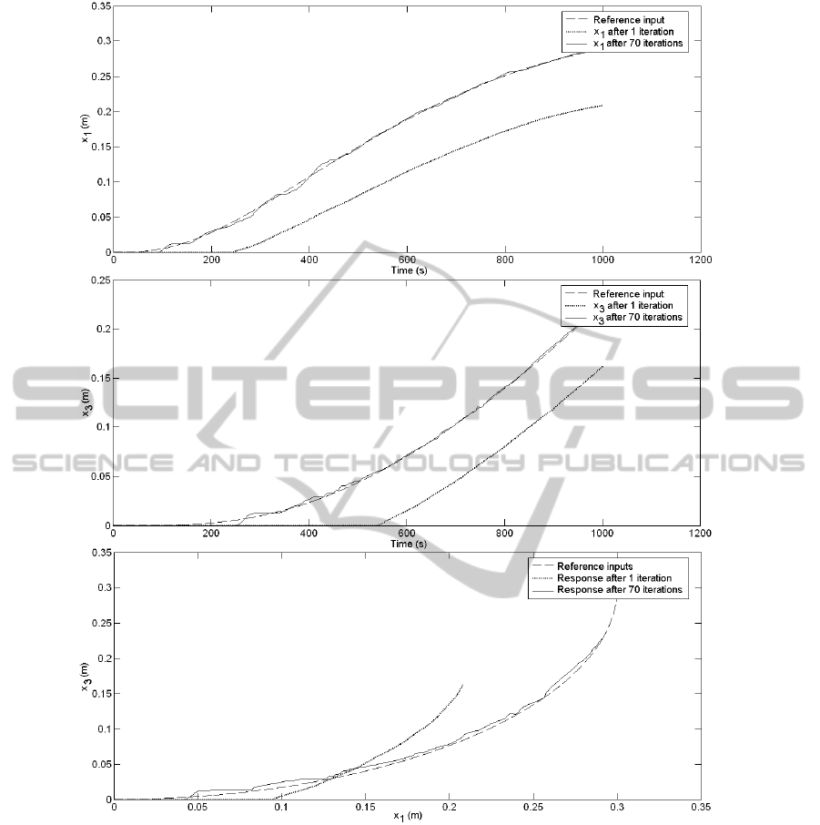
Figure 2: Experimental results: the system responses after 1 and after 70 iterations for the ILC-based control system
structure with CL.
because of its simplicity in the design. Therefore it is
applicable to other nonlinear processes in various
fields (Cottenceau et al., 2001; Horváth and Rudas,
2004; Škrjanc et al., 2005; Johanyák et al., 2006;
Bellomo et al., 2008; Bernard and Tichkiewitch,
2008; Derr and Manic, 2008; Vaščák, 2009). The
only constraint concerns the repeatability of the
inputs and of the initial conditions related to the
control systems.
Future research will be focused on the
application of our ILC-based control structures to
the z-axis crane position control problem and to the
anti-swing control problem. The extensions to
discrete-time control system structures are aimed.
ACKNOWLEDGEMENTS
This work was partially supported by the UEFISCDI
of Romania, and by the strategic grant POSDRU
6/1.5/S/13 (2008) of the Ministry of Labour, Family
and Social Protection, Romania, co-financed by the
European Social Fund – Investing in People.
ITERATIVE LEARNING CONTROL APPLICATION TO A 3D CRANE SYSTEM
121

REFERENCES
Ahn, H.-S., Moore, K. L., Chen, Y., 2007. Iterative
Learning Control. Robustness and Monotonic
Convergence for Interval Systems. Berlin, Heidelberg,
New York: Springer-Verlag.
Bellomo, D., Naso, D., Babuška, R., 2008. Adaptive fuzzy
control of a non-linear servo-drive: theory and
experimental results. Engineering Applications of
Artificial Intelligence. 21, 846-857.
Bernard, A., Tichkiewitch, S. (Eds.), 2008. Methods and
Tools for Effective Knowledge Life-Cycle-
Management. Berlin, Heidelberg, New York:
Springer-Verlag.
Bristow, D. A., Tharayil, M., Alleyne, A. G., 2006. A
survey of iterative learning control. IEEE Control
Systems Magazine. 26, 96-114.
Chang, C.-Y., Chiang, K.-H., 2008. The nonlinear 3-D
crane control with an intelligent operating method. In
Proceedings of 2008 SICE Annual Conference. Tokyo,
Japan, 2917-2921.
Chen, W., Wu, Q., Tafazzoli, E., Saif, M., 2008. Actuator
fault diagnosis using high-order sliding mode
differentiator (HOSMD) and its application to a
laboratory 3D crane. In Proceedings of 17
th
World
Congress of the International Federation of Automatic
Control. Seoul, Korea, 4809-4814.
Chwa, D., 2009. Nonlinear tracking control of 3-D
overhead cranes against the initial swing angle and the
variation of payload weight. IEEE Transactions on
Control Systems Technology. 17, 876-883.
Cottenceau, B., Hardouin, L., Boimond, J.-L., Ferrier, J.-
L., 2001. Model reference control for timed event
graphs in dioids. Automatica. 37, 1451-1458.
Cuenca, Á., Salt, J., Sala, A., Piza, R., 2011. A delay-
dependent dual-Rate PID controller over an Ethernet
network. IEEE Transactions on Industrial Informatics.
7, 18-29.
Derr, K., Manic, M., 2008. Wireless based object tracking
based on neural networks. In Proceedings of 3
rd
IEEE
Conference on Industrial Electronics and Applications
(ICIEA 2008). Singapore, 308-313.
Enache, F.-C., 2010. Iterative learning control-based
control solutions. Applications to a 3D crane
laboratory equipment. B.Sc. Thesis, Department of
Automation and Applied Informatics, “Politehnica”
University of Timisoara, Timisoara, Romania.
Horváth, L., Rudas, I. J., 2004. Modeling and Problem
Solving Methods for Engineers. Burlington, MA:
Academic Press, Elsevier.
Inteco Ltd, 2008. 3D Crane, User’s Manual. Krakow,
Poland: Inteco Ltd.
Johanyák, Z. C., Tikk, S., Kovács, S., Wong, K. K., 2006.
Fuzzy rule interpolation Matlab toolbox - FRI toolbox.
In Proceedings of 15
th
International Conference on
Fuzzy Systems (FUZZ-IEEE’06). Vancouver, BC,
Canada, 1427-1433.
Kaneshige, A., Miyoshi, T., Terashima, K., 2009. The
development of an autonomous mobile overhead crane
system for the liquid tank transfer. In Proceedings of
2009 IEEE/ASME International Conference on
Advanced Intelligent Mechatronics (AIM 2009).
Singapore, 630-635.
Pisano, A., Scodina, S., Usai, E., 2010. Load swing
suppression in the 3-dimensional overhead crane via
second-order sliding-modes. In Proceedings of 11
th
International Workshop on Variable Structure Systems
(VSS 2010). Mexico City, Mexico, 452-457.
Škrjanc, Blažič S., Agamennoni, O. E., 2005.
Identification of dynamical systems with a robust
interval fuzzy model. Automatica. 41, 327-332.
Vaščák, J., 2009. Using neural gas networks in traffic
navigation. Acta Technica Jaurinensis, Series
Intelligentia Computatorica. 2, 203-215.
Westerberg, S., Manchester, I. R., Mettin, U., La Hera, P.,
Shiriaev, A., 2008. Virtual environment teleoperation
of a hydraulic forestry crane. In Proceedings of 2008
IEEE International Conference on Robotics and
Automation (ICRA 2008). Pasadena, CA, USA, 4049-
4054.
Xu, J.-X., Panda, S. K., Lee, T. H., 2009. Real-time
Iterative Learning Control. Design and Applications.
Berlin, Heidelberg, New York: Springer-Verlag.
Yoshida, Y. Tabata, H., 2008. Visual feedback control of
an overhead crane and its combination with time-
optimal control. In Proceedings of 2008 IEEE/ASME
International Conference on Advanced Intelligent
Mechatronics (AIM 2008). Xi’an, China, 1114-1119.
ICINCO 2011 - 8th International Conference on Informatics in Control, Automation and Robotics
122
