
Data Mapping Model for User Programmable
Web-based Mashup
Eunjung Lee, Hyung-Ju Joo and Kyong-Jin Seo
Computer Science Department, Kyonggi University, Yi-ui Dong, Suwon, South Korea
Abstract. In this paper, we present a modeling tool for web-based mashups.
This tool allows users to design data relays between mashup methods using an
intuitive interface; the result is exported as a data mapping graph. We also
present a method to generate client codes wherein the data mapping graph
governs the navigation/mashup behavior by dynamically generated context
menus.
1 Introduction
A web-based mashup is a new type of web-based application in which a client page
includes more than one service and controls their flows and data relays. Moreover,
with the increasing popularity of user programmable mashups in the last few years,
users often desire to program mashups by combining and reusing existing web-based
resources within minutes [1,2]. There are several well-known techniques for the code
generation of a client page for a given set of service methods. Further, services and
data composition have also been highly researched.
There have been many researches on user interface development for service com-
positions. Lecue et al analyzed the types of data compositions and developed XSL
adapter modules to automatic data flows [3]. Moreau et al. proposed an evaluation
method to select the best data mapping from possible candidates [4]. On the other
hand, Liu et al studied mashup as a special case of service compositions, and pro-
posed hosting site architecture to provide service mashup [5]. Nestler et al proposed a
model driven approach to develop user interface for service compositions [6]. Au-
thors' previous paper presented a code generation approach for client side service
navigations [7]. Recently, Pietman present CRUISe system, a client-side service inte-
gration framework[8]
In this paper, we describe a method to make it possible to allow users to design ta-
ble-driven data mapping relations in order to control the navigations of the final gen-
erated codes. A user-designed graph can be used to govern a client page’s behavior
using dynamically generated context popup menus.
The client page is responsible for communicating with service sites, presenting
views for user actions, determining available service mashups from the currently
selected data, and providing user interface menus for transferring data and requesting
the next method. In Figure 2, the client page navigates views and service calls for
Lee E., Joo H. and Seo K..
Data Mapping Model for User Programmable Web-based Mashup.
DOI: 10.5220/0003560400410048
In Proceedings of the International Joint Workshop on Information Value Management, Future Trends of Model-Driven Development, Recent Trends in
SOA Based Information Systems and Modelling and Simulation, Verification and Validation (RTSOABIS-2011), pages 41-48
ISBN: 978-989-8425-60-7
Copyright
c
2011 SCITEPRESS (Science and Technology Publications, Lda.)
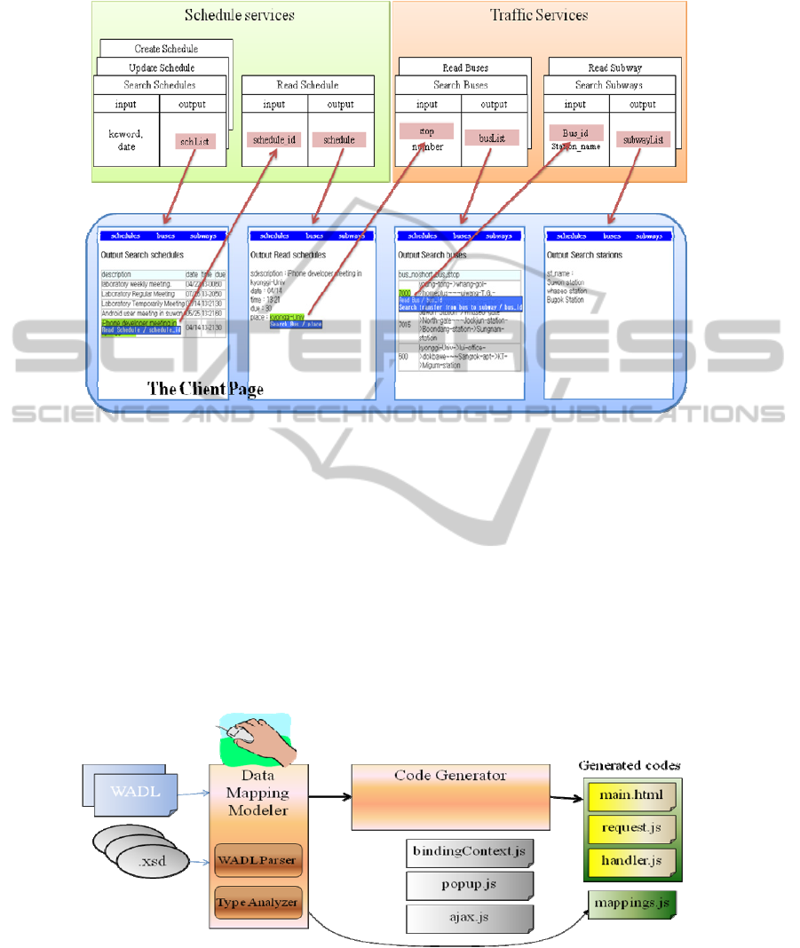
Fig. 1. Service Interfaces and Navigations of a Client mashup page.
given set of service methods. By using the context popup menus, users can navigate
and connect mashup service requests.
The main contribution of this paper is the introduction of a data mapping modeler
that allows users to model service compositions and data flows. Further, the proposed
modeler helps users to design data mapping from output data to input parameters with
intuitive interfaces; the modeler generates a table-driven data structure for code
generation. Our code generation system generates response handler functions which
enable to utilize the data mapping table in order to create context popup menus.
This paper is organized as follows: Section 2 describes our approach, and section 3
introduces data mapping model and the editing tool. Section 4 presents the implemen-
tation of code generation system and section 6 concludes the paper.
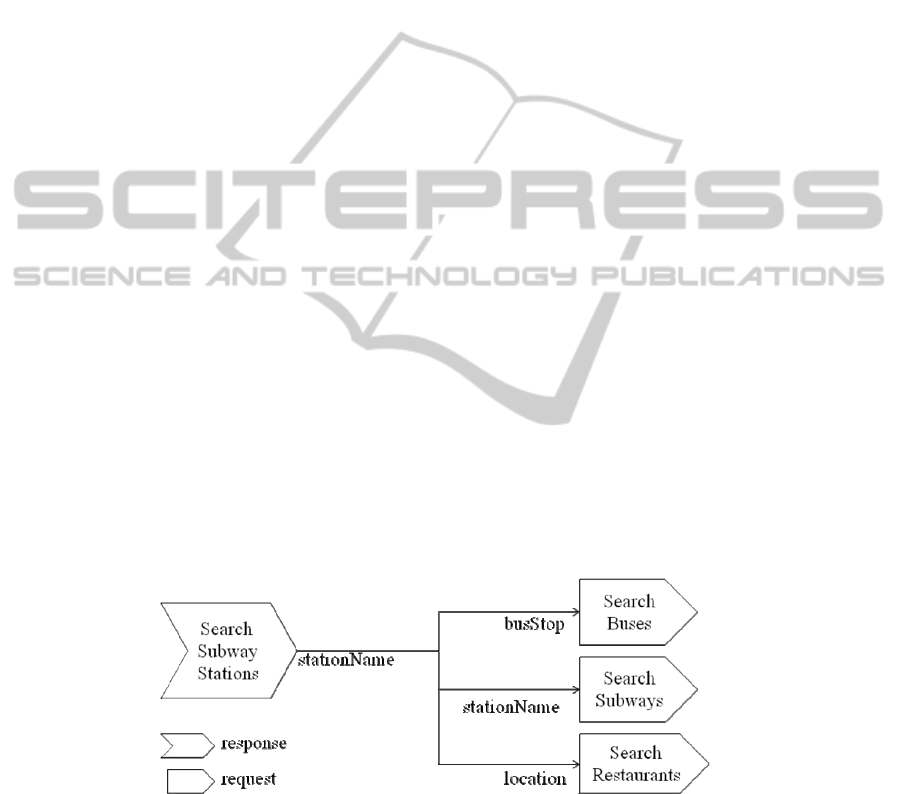
Fig. 2. System architecture of our approach.
42
2 Our Approach
Figure 2 shows the overall architecture of our model driven development. Data
mapping modeler analyzes the method information and generates data mapping table
for the selected set of methods. Then, the code generator generates views, request and
response handler functions. There are several helper javascript files given in from
(gray js boxes), and the generated codes (green boxes).
The goal of the data mapping modeler is to design a data mapping graph that is de-
fined as follows:
Definition 1. Let M be a set of methods that a user wants to interface. For a given
method m
∈
M, let input(m) be a set of parameter names and output(m) be the set of
terminal node tags of m. Then,
DataMappingGraph = (O
∪
I, E)
Here O = {(m, t) | m
∈
M, t
∈
output(m)}; I = {(m, t) | m
∈
M, t
∈
input(m)}; and
E
⊂
O
×
I.
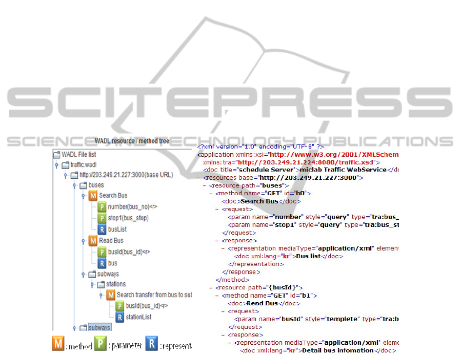
Figure 3 shows an example of a part of the data mapping graph. A data mapping
implies data relay from a method response to an input parameter of another method.
In other words, μ = (m
1
, t
1
, m
2
, t
2
)
∈
E means that m
2
is the connected request me-
thod and t
2
is the corresponding input parameter name relayed from method m1 and
the data element with tag t
1
. Such a mapping can be directly applied to user interfaces
for connected mashup requests. Here, the user interface is a popup context menu. For
example, the first popup menu item in Figure 1 represents a mashup request from the
mapping (Search Schedules, sch_id, Read Schedule, sch_id).
In the next section, we present the modeling using data mapping modeler in detail.
The designed result is serialized as a javascrpt table in mappings.js in Figure 2.
When a properly designed data mapping graph is given, we can generate codes for
client mashups. As part of the response handler (part of handler.js in Figure 2), a
presentation object is created and a context menu is attached when it exists. A java-
script function can generate a context menu code dynamically from the data mapping
graph.
Fig. 3. A part of data mapping graph: edges from the node (Search Subway Stations, station-
Name) ∈ O.
43
3 Data Mapping Modeler
Data mapping modeler is responsible for (1) providing user interface to select me-
thods from WADL specifications, and (2) providing user interface to model data
mapping relations between methods.
For a client page, a service environment is defined as a set of available services,
which is described in a service specification. Usually, service specification includes
type, url, method signature for service method. Method signature defines the output
data type and a set of input parameter types. We have used web application descrip-
tion language (WADL) as the service specification language [9]. WADL is a standard
for describing REST style services for specifying available services. In order for data
mapping of service compositions, we extended a "type" attribute to input parameter
tag <param>.
The modeler provides a friendly interface by using the descriptions in the service
specification files to show the method and parameter names. Figure 4 (a) shows
WADL service specification example and the corresponding WADL tree in (b). Users
can select a set of service methods from the tree which are included in the service
environment of the mashup client .
Fig. 4. A part of WADL specification and the WADL tree view in the data mapping modeler.
Figure 5 shows a screenshot of the data mapping modeler that helps users to design
connected requests and data relays between methods. After the user selects a set of
service methods in the page, the tool shows the service output data elements in the
left top pane (1) and the input parameters in the right top pane (2). Further, the tool
analyzes the relationship between data elements to determine the mapping candidates
of the same type (3), which the users can select. On the other hand, users can add any
44
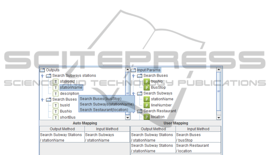
two data elements, which are listed in pane (4), by connecting them in the modeler
interface.
The mapping is from the output terminal data elements to the input parameters.
The tool includes an automatic mapping to M (in pane (3)) if a terminal element of
the result data has the same name (same namespace tag) as the input parameter. The
modeler shows the connected method requests with a quick view, as shown in Figure
5, which allows intuitive design of mashups.
The mashup design results are exported as an associative array for use by the code
generator. The key of the associative array is the (method, tag) pair, and the value is
the corresponding list of connected requests. The design results are as follows:
MT = {(m
i
, t
i
) : [(m
i1
, p
i1
), (m
i2
, p
i2
), …, (m
ik
, p
ik
)]
| 0 ≤ i ≤ n, n is the number of mapped output nodes}.
Therefore, (m
2
, t
2
)
∈
MT(m
1
, t
1
) means the relation where a data of type t
1
of out-
put tree m1 can be transferred to method m2 for an input parameter of type t
2
. Since
The modeler can analyze the type information of method signature, we can serialize
the type mapping relations into a hashmap of javascript code at static time.
Fig. 5. Screenshot of data mapping modeler.
4 Implementation Result
In this section, we present the code generation approach from the model introduced
so far. We implemented the data mapping model into the code generation system
developed by authors[7].
List 1 shows the overall algorithm of code generation using the modeler’s output
MT. When a service response arrives from the server, the algorithm generates an
output view code for the response tree T. For each terminal node n, a presentation
element <span> is created along with the associated context popup menu. The func-
tion prepareContextMenu() uses MT to determine the connected requests and generate
the mouse event handler for mashup calls.
45

List 1. Algorithm of mashup code generation using the data mapping model.
[Algorithm 1] Mashup code generation algorithm
Input: m: responding method just responded,
T: output tree of m,
MT: data mapping table, modeler’s output.
Output: The generated code for the output view.
including mashup context menu handler.
1) For each terminal node node of T,
1-1) tag = node.tag, value = node.text.
1-2) create <span> element e for value.
1-3) if MT(m, tag) ≠ ∅,
1-3-1) add onmouseover event handler to e,
1-3-2) call prepareContextMenu(e, m, tag, value),
1-3-1) menuDiv.show().
function prepareContextMenu(e,m
1
,t
1
,v)
Reset menuDiv.
∀(m
2
, t
2
) ∈ MT(m
1
, t
1
),
Add menu item “request m
2
with t
2
”.
Add a mouse handler; Call m
2
using v.
List 2 shows the data mapping table generated from the data mapping modeler. It
is serialized as javascript code where a key is a pair of method id and the parameter
name and the value is an array of the pairs of mashup methods and transfer data type.
Code generation system utilizes this information in order to reflect the modeling re-
sult which is designed at the modeler. Moreover, request function name and the doc
info for methods are also generated as javascript hash maps as shown below.
List 2. Serialized table data structure for the code generation system.
mappingTable={'b1/bus_stop':['b0/stop1'],'s2/st_name':['s1/name'],'b0/bus_no':['b0/bus…
reqMethodInfo={'b1/busId':['requestReadbuseBybusId_b1'],'b0/number':['requestSearc…
methodInfo={'b0':['Search Buses'],'b1':[Read Bus'],'s1':['Search Stations'],'s2':[‘Read S…
Figure 6 shows implementation result. The output view has context popup menus
as designed in data mapping table. Output handler function generates output data
presentations using the repeat structure presentation method (refer [7] for detail). We
extended the code with a line “constructReqDiv()” function call, which calls a static
function in popup.js file. This function creates context popup menus dynamically
depending on the data mapping table(the italicized line in Figure 5(c)).
The proposed approach is different from other tools and studies in several aspects
[4,5,8]. Although current user programmable mashup tools often create server side
services, our tool generates client code that is ready to use by end users. Moreover,
the data mapping modeler is easy to use since it provides an intuitive tooltip of navi-
gation menus, and the modeler output-data mapping graph governs the dynamic con-
text menu behavior as designed by the user.
On the other hand, CRUISe system proposed in [8] aims a client side mashup execu-
tion framework in model driven development, which is in common with our approach.
46
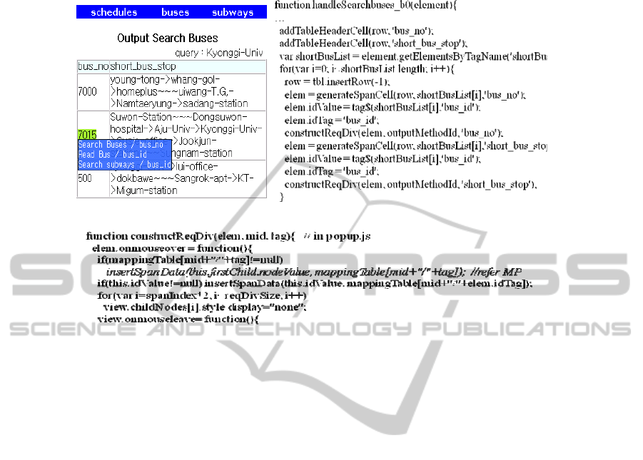
(a) An output view(part) (b) handler function of Search Bused (generated part)
(c) A javascript function for constructing context menus using the table (in popup.js)
Fig. 6. The result view with context popup menus and the code generated.
However, one of their main goals is to achieve language and platform independence,
contrary to our javascript specific code generation system. In our opinion, our system
is more efficient and light-weighted because we fixed the target environment and
platform. Moreover, our result code is ready to run, as well as easier to update by
developers for the application.
5 Conclusions
In this paper, we have proposed a data mapping graph and a modeler tool that allows
users to design request flows and mashups on the client webpage.
We are now working on extending the proposed modeler and code generator to in-
clude more types of data mapping and styles of mashups and generalize it further.
Furthermore, we also plan to integrate the proposed system into a service framework
including service discovery and context-aware service paradigms.
References
1. Jhingran, A.: Enterprise information mashups:integrating information, simply. VLDB’06
(2006) 3-4
47

2. Yu, J. et al.: Understanding mashup development. vol.12 issue 5. IEEE Internet computing.
(2008) 44-52
3. Lecue Freddy Lecue, Samir Salibi, Philippe Bron, Aur?lien Moreau: Semantic and Syntac-
tic Data Flow in Web Service Composition. ICWS ‘2008, IEEE International Conference
on Web Services. (2008) 211-218
4. Aurélien Moreau, Jacques Malenfant: Data Flow Repair in Web Service Orchestration at
Runtime. ICIW '09. (2009) 43-48
5. Xuanzhe Liu, Yi Hui, Wei Sun, Haiqi Liang: Towards Service Composition Based on
Mashup. IEEE Congress on Services. (2007) 332-339
6. Tobias Nestler: Towards a Mashup-driven End-User Programming of SOA-based Applica-
tions. iiWAS '08. (2008) 551-554
7. Lee Eunjung Lee and Kyong-Jin Seo: Designing Client View Navigations Using Rest Style
Service Patterns. WEBIST’2010, (2010)
8. Stefan Pietschmann, Johannes Waltsgott, Klaus Meißner, : A Thin-Server Runtime Plat-
form for Composite Web Applications. ICIW '10. (2010) 390-395
9. Web application description language (WADL), http://www.w3.org/Submission/wadl.
48
