
Model-driven Testing Approach for Embedded Systems
Specifics Verification based on UML Model
Transformation
Jurijs Grigorjevs
Riga Technical University, Faculty of Computer Science and Information Technology
Riga, Latvia
Abstract. This paper is devoted to a model-driven testing approach for embed-
ded system’s non-functional requirements. The method is based on UML state
and sequence diagrams suitable for synchronization, asynchronous behavior
and timing constraints presentation. The article discusses principles of model
transformation and shows a practical approach of a testing model generation
from a system model. The idea of such transformation is to generate test cases
focused on specific behavior verification of embedded systems. In the paper
described example presents method approbation within timing behavior verifi-
cation using the UML sequence diagram. Presented example is based on a se-
quence diagram XMI representation, which firstly is pre-processed and moved
into data base structures and then transformation rules are applied to generate
the testing model. In the result of such transformation a set of valid and invalid
test cases is generated in a form of the UML Testing profile.
1 Introduction
Embedded system cooperation with external environment requires a special hardware
and software as well as approaches of software development to provide high quality
of an embedded system. Therefore, embedded systems are characterized by the set of
special features, which require specific internal structure, processing principles and
mechanisms. Synchronization, asynchronous behavior and timing constraints are the
major non-functional features of the embedded system software, which require addi-
tional activities during implementation and testing processes [1]. In the previous re-
searches [1] [2] modeling notations for the mentioned features have been analyzed
and compliance of the UML language to them has been shown.
In the same time automation in software development becomes more and more
popular. Program code generation is known and used for many years, but still auto-
mation of a full development cycle is under research and on its way to replace manual
operations in this cycle. Standardized principles of an MDA [3], available develop-
ment environments and tools stimulate movement to automation. Similar ongoing
activities are also in a testing area. There are more than 5 years left since OMG has
provided the Testing profile for a test data management, but still there are no common
methods of automated test case generation from system models.
Grigorjevs J..
Model-driven Testing Approach for Embedded Systems Specifics Verification based on UML Model Transformation.
DOI: 10.5220/0003563700260035
In Proceedings of the 3rd International Workshop on Model-Driven Architecture and Modeling-Driven Software Development (MDA & MDSD-2011),
pages 26-35
ISBN: 978-989-8425-59-1
Copyright
c
2011 SCITEPRESS (Science and Technology Publications, Lda.)

This article presents testing approach for the embedded system specifics verifica-
tion using a UML diagrams. The concept of the presented approach is based on prin-
ciples of model-driven development (MDD) of automated model transformation with
the goal to generate the set of necessary test cases for specific features testing. Im-
plementation of the approach for timing aspects verification is presented in the paper.
1.1 Specifics of Embedded Systems
Embedded systems are the systems where hardware and software are a part of com-
plex systems and are scheduled for functioning of specific usage without interference
of humans. To fulfil managing of devices without interaction and other activities
embedded software should support the following non-functional requirements [1]:
Asynchronism – a property of the systems, where events and actions can occur
independently in time and order.
Synchronization – the mandatory non-functional requirement in asynchronous sys-
tems with multiple devices. Process synchronization refers to the coordination of
simultaneous threads or processes to complete a task in order to get correct runtime
order and avoid unexpected race conditions.
Time constraints – modelling elements to define time preconditions for some activ-
ity or activity set. The concept of a real-time system supposes that preciseness in time
is more important than preciseness of a software function.
Above mentioned requirements are typical for the most of embedded systems and
often could be required in other software systems.
1.2 Current Modeling and Verification Methods
All mentioned features are not new in software development and they could be met
also in other non-embedded systems. Due to this fact currently there are different
modeling notations suitable for these features representation. The most popular pre-
vious generation notation is the Petri net. There are number of Petri nets extensions,
covering all major requirements for modeling of parallel processes, synchronization
and time constraints. The most popular are Timed Petri nets [4], PRES+ [5] and co-
lored Petri nets [6]. All these extensions were popular until the unified modeling
language took the leadership in software modeling process. Still these notations could
be used for modeling of these features, but further usage and processing of such mod-
els could not be effective as in case with UML models. UML models are supported
by large number of available tools. In the same time the UML provides various struc-
tural and behavioral diagrams, which are used for the mentioned specification.
Currently known testing methods of timing constraints and asynchronous
processing verification include general testing approaches. Such methods are applied
in manual testing, but in context of model-driven development with automated test
case generation methods are insufficient to provide an effective testing process. Op-
posite these features, verification of synchronization could be provided with formal
verification methods, which are not suitable in the context of the MDA and the UML.
27

2 Principles of the Model-driven Approach in the Context of
System Testing
Generally, model-driven testing defines a test case development strategy using a
model of the system under test [7]. Sets of test data, preconditions and test exit crite-
ria are created from the abstract functional model, representing functional and non-
functional aspects of the system. Automated test case generation becomes more and
more popular. There are two major reasons for that. The first reason is to cut time-to-
market and to deliver products faster with higher quality [8]. The popular idea, to
start testing earlier, is going to be realized in model-driven testing. During an analysis
phase models of a system, describing its functional and technical aspects, are created.
This means immediate start of the testing process without waiting for programming
activities. The second major reason to use model-driven testing is compliance to prin-
ciples of model-driven development, where models are basic system specification
documents. In this case model transformation and generalization is compliant to the
classical testing V-model [7], where the main idea of the model is not to show appro-
priate related activities, but to represent a program abstraction level (for example, to
show that system testing deals with a whole fully integrated system and user accep-
tance testing verifies and validates end-user requirements).
2.1 Modeling Artifacts in a Context of Testing
By the nature, a test case can be represented as a model, because it also consists of
elements, which describe an abstract reality. A testing model is a set of preconditions,
data inputs and expected results for some program functionality. Test case generation
in model transformation means processing of transformation rules towards system
models.
A projection of model-driven development definitions of a model, metamodel and
model transformations into a process of testing gives a possibility to define test case
generation process in terms of model transformations under main statements of mod-
el-driven approach. An appropriate metamodel should be defined before development
of a model. Metamodels are based on the Meta Object Facilities (MOF) [10].
In this paper author describes a source and test case model necessary for a system
and a test case specification. In next chapters author deals with the system source
model based on the UML state and sequence diagrams and the test case model based
on the concepts taken from the UML Testing profile [11]. The last profile provides a
standalone metamodel describing all necessary artifacts for test data management.
The UML state and sequence diagrams provide specification of a system dynamical
behavior including timing aspects.
MDD principles are based on a model transformation, where new models are
created from existent models applying special transformation. The transformation
between models is made by the transformation definition, which is a collection of
transformation rules in the form of an unambiguous specifications of the way that (a
part of) one model can be used to create (a part of) another model [9]. Transformation
rules are presented with a predefined transformation definition language. An auto-
28
mated transformation of models can be provided only by a special tool, which is able
to understand a notation of a source and target models and to apply transformation
rules according to their logic to a given source model. The result of such process is a
set of destination models. Basic MDA framework described in [9] defines a general
scheme for transformations between models. Same principles are applied in test case
model generation, where test case models are created from one or more system mod-
els.
2.2 UML Diagrams and Testing Profile
In [1] [2] different modeling notations for embedded systems are analyzed with con-
clusion about UML diagrams advantage over other notations for asynchronous beha-
vior, synchronization and timing details specification. Based on this analysis UML
diagrams are chosen as source models for system specification. Both diagrams are
widely used for system dynamic behavior specification, including mentioned features.
Timing specification in most cases is related to time limitations for operations of
other objects or components. Similar behavior is typical also for asynchronous
processing, where two or more processes communicate in-between through asyn-
chronous or synchronous calls and signals. This means that the sequence diagram is
preferable for timing and asynchronous behavior specification, while the state dia-
gram could also be applied in some cases. Opposite to this, synchronization specifica-
tion for a particular object requires detailed definition on object level, what is an area
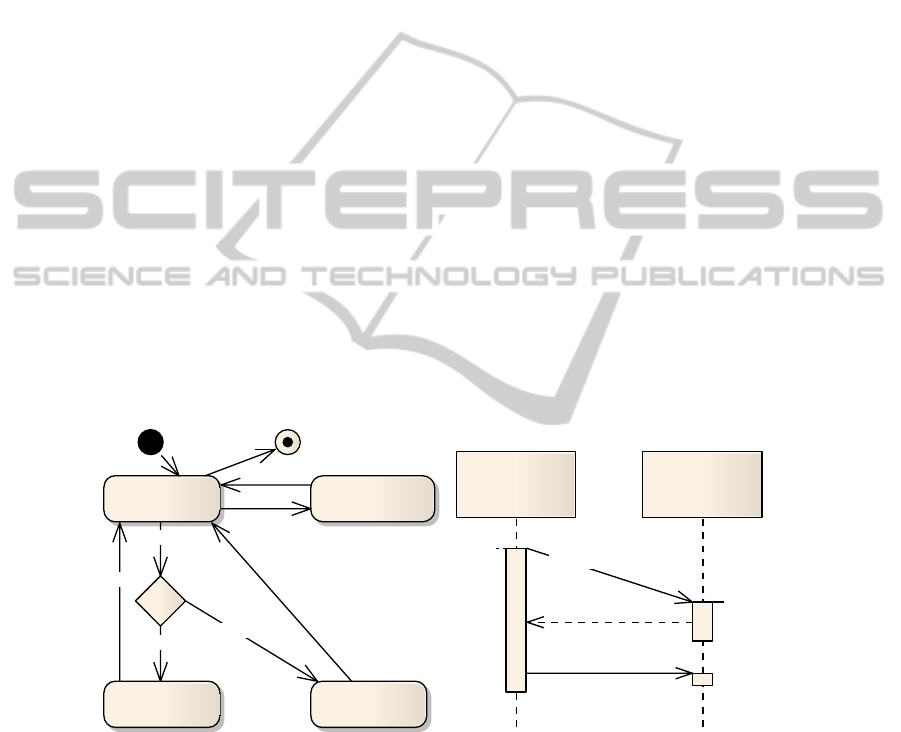
for the state diagram. Figure 1 shows asynchronous and synchronous behavior with
time constraints specified by the sequence diagram and synchronization example
defined within the state diagram.
Initialize
Ready
Shutdown
NoResourcesGotResource
ResourceReleased
free=9
getResource
[free-1 >= 1]
[free-1 < 1]
--free
release
++free
Process1 Process2
{t < 10}
t
synchCall() {1..3} d
asynchEvent()
Fig. 1. Examples of the state and sequence diagrams.
In a context of timing specification the UML sequence diagram provides defini-
tion of two types of limitations: time and duration constraints. The time constraint
defines time requirements at some point during processing. The duration constraint
defines time limitation between two points in time, for example, between message
sending and receiving.
29
For testing purpose OMG has created and standardized the UML Testing profile,
which is used for a test case model development. The profile provides standardized
approach for test cases and test suites implementation and it represents the MOF-
based standalone metamodel for testing aspects modeling. This profile suggests a new
approach for a testing system management, which consists of a test case, test data,
program’s behavior and test results. Using the Testing profile test cases and to them
related data could be stored and represented using defined elements of the metamo-
del. The profile describes major classes of testing aspects and suggests a general
approach of test data management. The profile does not specify any system related
aspects and leaves this for concrete systems developers. Such approach makes profile
to be widely used for different types of systems including embedded systems with
timing aspects, synchronization and asynchronism.
In the following section described approach currently does not cover functional
aspects of a system and does not use profile elements, which are focused on test data
definition including input and output data. Specification of such data is related to
functionality of a system and is left for future researches.
3 The Approach for Automated Test Case Generation
The concept of the approach is to use standardized model presentation, but perform
all processing and data generation in a database, because data manipulation and man-
agement is a purpose of it. Test data, as the result of model transformation, is stored
in appropriate tables and linked in-between. As input data an XMI (XML Metadata
Interchange) [12] representation of the system sequence diagram is used. The XMI is
a standard provided by OMG group for a UML model representation in the XML
format. It means that approach doesn’t have dependency on a model definition tool
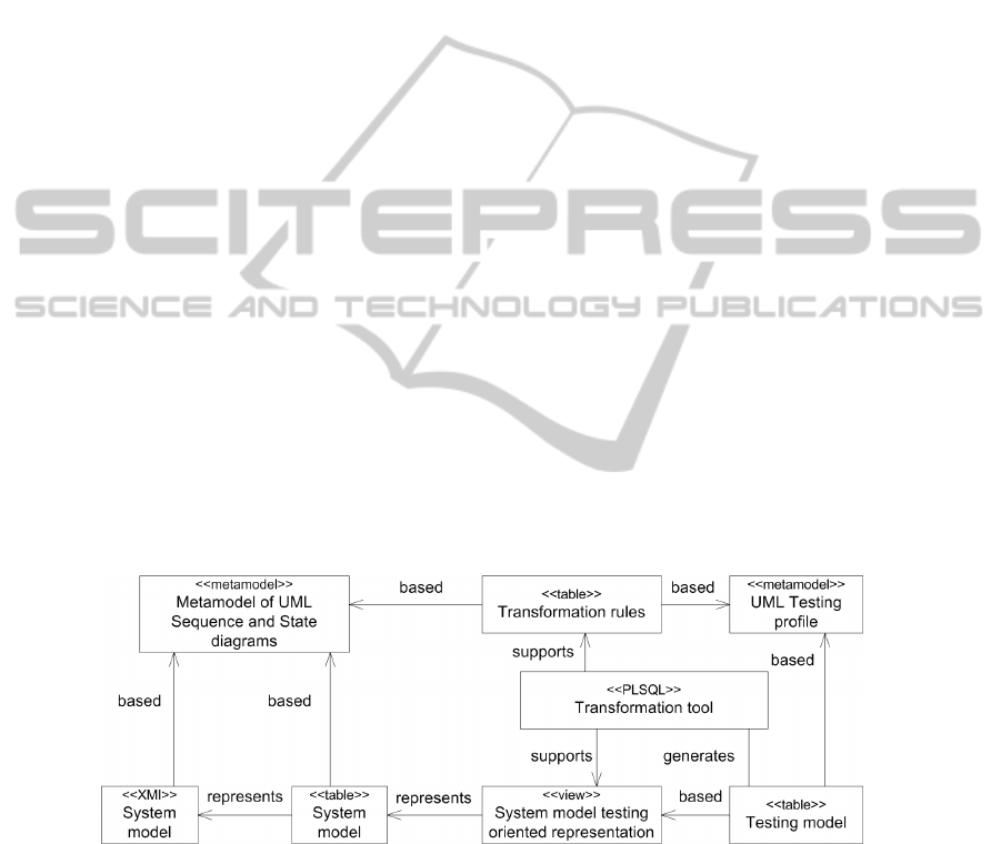
and various tools could be used for model development. Figure 2 presents principles
of proposed approach and dependencies between specified artifacts.
Fig. 2. Principles of the approach for automated test case generation.
The diagram is build to show the concept of the interrelated objects of the ap-
proach. Stereotypes are used in the diagram to show physical representation of a
defined object in the approach implementation, except a metamodel stereotype, which
means that this object is a notation for other models.
30

The approach is based on 3 steps necessary to transform system models and to
generate test cases. In step 1, only a technological representation of a system model is
changed from an XMI to a database format (data from an XML file is imported into
appropriate tables). This step is necessary to prepare all model related data for further
processing. In the result of this step a database structure with inserted data is re-
ceived. The structure of the database is based on the metamodel of the UML diagrams
and is appended with additional properties from the XML file (for example, parent
element type and parent element id). In general, for an each UML metamodel class
appropriate table with data is created.
Complete structure of the UML metamodel is made universal to support various
specifications. According to the XMI format of the UML sequence diagram, for ex-
ample, a class is linked to a message and timing details of it through 7 layers: Class
Property Lifeline OccurenceSpecification Message TimeConstraint
TimeExpression OpaqueExpression TimeObservation. For a test case genera-
tion purpose the system model should be presented in simplified format – views. Step
2 introduces views for messages and other objects presentation and includes all ne-
cessary details of them.
The transformation tool is developed as PL/SQL procedures with a set of addi-
tional functions to provide an affected system object selection, transformation rules
processing and test data generation. In step 3, transformation is done based on a sim-
plified model representation and test data is generated according to defined transfor-
mation rules.
3.1 The Approach Appliance for Timing Details Verification
As is mentioned in previous sections, transformation uses the UML state and se-
quence diagrams as source models and the UML Testing profile as a destination
model. For timing details verification the UML sequence diagram is chosen as a sys-
tem modeling notation [1]. Timing details are defined for different kind of messages
by the following UML classes: TimeObservation, DurationObservation, Observation,
TimeExpression, TimeInterval, TimeConstraint, DurationConstraint, DurationInter-
val, Duration, IntervalConstraint, Interval, ValueSpecification and OpaqueExpres-
sion. Well defined transformation rules require model simplification. For this purpose
all timing artifacts with appropriate message details are encapsulated into database
views, which still correspond to the UML metamodel. After such preprocessing,
transformation rules could focus only on their semantics and do not cover complex
relationship of the original sequence diagram. Figure 3 is the simplified conceptual
schema of data mapping between sequence diagram and Testing profile elements.
31
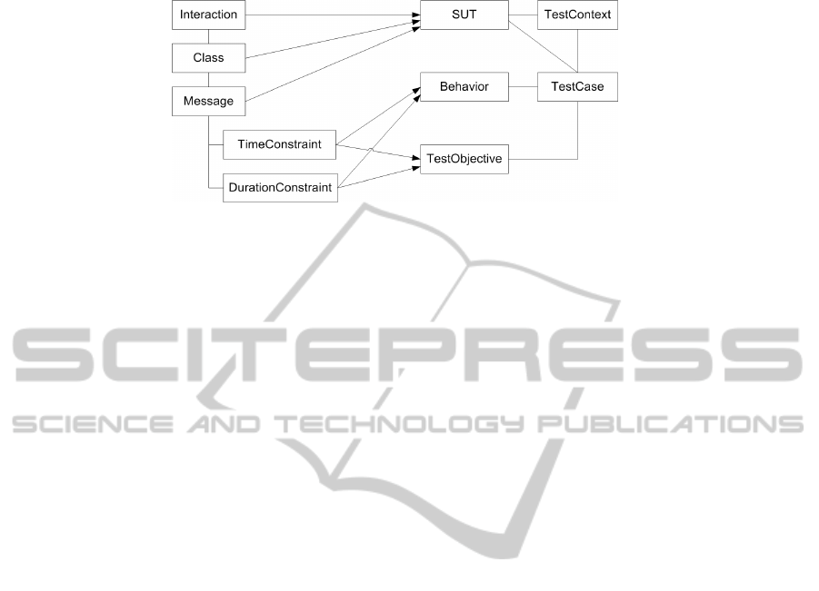
Fig. 3. A Conceptual mapping diagram between metamodels.
The approach uses 5 elements from the Testing profile: SUT, Behavior, TestOb-
jective, TestContext and TestCase. SUT element of the Testing profile describes a
system under test and contains information about system components. Behavior ele-
ment contains timing details definition of the tested components for a concrete test
case. TestObjective presents expected result for each test case and in same time Tes-
tObjective could be verified according to TimeConstraint and DurationConstraint of
the sequence diagram. TestCase together with related elements describes each inde-
pendent program execution situation. TestContext groups several test cases into sets
of them. Mapping definition of more general objects is done on transformation tool
level, but mapping of specific behavior objects is specified in rules.
3.2 Notation of the Transformation Rules
The transformation rules are defined and stored in the
TRANSFORMATION_RULES table according to a strictly predefined notation.
Described notation is applied for timing details verification, but its general specifica-
tion could be used also for other feature of the embedded system verification. During
transformation process each transformation rule sequentially is read from the table
and processed. General format of notation for test case generation transformation
rules is the following:
FOR: <object type> <object name> WITH: <precondition>
DO: <operation> WITH: <behavior def.> WHICH: <objective>
<object type> - defines type of the object to be processed during transformation. For
example, the object type MESSAGE could be specified.
<object name> - a name of the object to be selected for validation and processing. If
the transformation rule is applied to all objects of the specified type, “*” should be
used. Otherwise, exact name of the object of appropriate type should be specified.
<precondition> - a precondition section for object selection. The precondition should
be written in a SQL statement WHERE clause format, which is activated during
search of objects to be processed.
<operation> - an activity that should be processed with found objects. Currently sup-
ported operation is “CREATE_TC” – a new test case creation for an activated rule
32
and a found object.
<behavior definition> - a definition of a timing behavior of the affected object in the
created test case. 2 options are supported for the behavior definition:
• static definition – when timing aspects of the object are specified by static data.
For example, “durationconstraint=0”, “timingconstraint=99” and similar;
• dynamic definition – when timing aspects are defined with a mean of data from
specification. Timing aspects (duration and timing constraints) according to UML
could be specified in time interval format: like interval between min and max
(1..7) or “less”, ”more”, ”less or equal”, ”more or equal”, ”equal” (“t<=4” or
“d>5”). In such case the behavior definition could use 2 predefined words “min”
and “max” for value specification. For example, “durationconstraint = min +1” or
“timingconstraint = max + 2”. In case of dynamic definition test case behavior
will be automatically calculated based on specification from system model and
behavior definition from transformation rule.
<objective> - objective of the generated test case. In this section expected result of
the generated test case is specified.
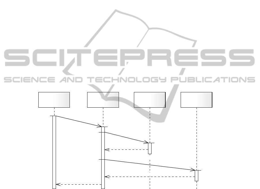
4 Practical Outline of a Model Construction
A_unit B_unit C_unit D_unit
{t < 6}
t
a_to_b()
{d <30} d
{t < 10}
t
b_to_c1()
{1..3} d
b_to_c1_resp()
{t <15}
t
b_to_c2()
{2..4} d
b_to_c2_resp()
b_to_a()
Fig. 4. Example of a sequence diagram with time constraints.
The implemented approach approbation is based on a simple sequence diagram with
several messages transmissions with timing constraints. Figure 4 shows this sequence
diagram and time constraints.
For transformation the following 3 rules are defined:
FOR: MESSAGE * WITH: timingconstraint is not null DO:
CREATE TC WITH: timingconstraint = max + 1 WHICH:
EXPECTED_RESULT = FAILED
33

FOR: MESSAGE b_to_c1 WITH: durationconstraint is not null
DO: CREATE TC WITH: durationconstraint = max WHICH:
EXPECTED_RESULT = SUCCES
FOR: MESSAGE * WITH: timingconstraint is not null DO:
CREATE TC WITH: timingconstraint = max -1 WHICH:
EXPECTED_RESULT = SUCCES
In result 7 test cases with the following behaviors and objectives are generated.
BEHAVIORDEFINITION TESTOBJECTIVE
for MESSAGE b_to_c2 timeconstraint = 16 FAILED
for MESSAGE a_to_ timeconstraint = 7 FAILED
for MESSAGE b_to_c1 timeconstraint = 11 FAILED
for MESSAGE b_to_c1 duration = 3 SUCCES
for MESSAGE a_to_b timeconstraint = 5 SUCCES
for MESSAGE b_to_c1 timeconstraint = 9 SUCCES
for MESSAGE b_to_c2 timeconstraint = 14 SUCCES
The idea of this approbation is to show usage of MDD principles in test case genera-
tion. These examples cover timing constraints verification according to the transfor-
mation rules. The result of such generation is the set of test cases of all system com-
ponents, which satisfy conditions in the transformation rules. In such cases test objec-
tive is taken from the transformation rule, but in the same time it also is generated
based on the constraint evaluation.
5 Conclusions
Embedded systems are specific and require additional non-functional requirement
implementation, such as asynchronous behavior, synchronization and timing con-
straints. Model-based software development becomes more and more popular and
usage of models as a main specification objects can’t be postponed anymore. In the
paper presented approach for test cases development follows up MDD principles of
model transformation and is based on the UML diagrams. The approach covers com-
mon principles of model-based testing for embedded systems and could be used both
for functional and non-functional features verification.
Author provides approach’s implementation for timing details testing, where the
sequence diagram is used as a source model to describe a system dynamic behavior
including time constraints. The UML Testing profile is selected as a destination mod-
el to define test cases and to them related aspects. During the transformation devel-
opment it was stated that transformation rules for direct transformation from the se-
quence diagram to the Testing profile became complicated and require simplification.
For this purpose suggested approach includes an addition step of a source data pre-
processing to simplify them and to make them ready for transformation rules. After
such preparation transformation rules could focus only on logical data manipulation.
From technical point of view described implementation is based on the XMI stan-
dard. This option allows use of various UML diagram development tools. Transfor-
mation rules and source models are stored in database and the transformation tool is
34

developed in PL/SQL. Transformation results to new data generation, which complies
with the UML Testing profile.
Developed transformation tool has limitations and currently supports only timing
details verification from the sequence diagram. The structure of the tool is able to
extent its functionality and after improvements it could support other UML diagrams.
References
1. Grigorjevs, J., Nikiforova, O.: Modeling of Non-Functional Requirements of Embedded
Systems, Scientific Proceedings of 42nd Spring International Conference MOSIS2008,
MARQ, Ostrava (2008) pp. 13-20.
2. Grigorjevs, J., Nikiforova, O.: Compliance of Popular Modeling Notations to Non-
functional Requirements of Embedded Systems, in Proceedings of the International Scien-
tific Conference Informatics in the Scientific Knowledge 2008, University publishing
house VFU “Chernorizets Hrabar”, Varna (2008) pp. 139-149.
3. OMG. Model Driven Architecture. Retrieved from: http://www.omg.org/mda/
4. Ghezzi, C., Mandrioli, D., Morasca, S., Pezze, M.: A general way to put time in Petri nets,
Proceedings of the 5th international workshop on Software specification and design (1989)
pp. 60-67.
5. Cortés, L. A., Eles, P.: Verification of Embedded Systems using a Petri Net based Repre-
sentation (2000).
6. Jensen, K.: Coloured Petri nets, Petri Nets: Central Models and Their Properties, Lecture
Notes in Computer Science (1987) pp. 248-299.
7. Spillner, A., Linz, T., Schaefer, H.: Software Testing Foundations, Santa Barbara, Rocky
Nook Inc. (2007).
8. Engels, G., Guldali, B., Lohmann, M.: Towards Model-Driven Unit Testing. Retrieved
from: http://citeseerx.ist.psu.edu/viewdoc/summary?doi=10.1.1.62.200.
9. Kleppe, A. G., Warmer, J., Bast, W.: MDA Explained: The Model Driven Architecture:
Practice and Promise, Addison Wesley Professional (2003).
10. MOF. OMG's MetaObject Facility. Retrieved from: http://www.omg.org/mof/
11. OMG. UML Testing Profile, v 1.0. Retrieved from: http://www.omg.org/technology/
documents/formal/test_profile.htm.
12. OMG, XML Metadata Interchange, v 2.1.1. Retrieved from: http://www.omg.org/
spec/XMI/2.1.1.
35
