WIRELESS IN-VEHICLE COMPLAINT DRIVER
ENVIRONMENT RECORDER
Oscar S. Siordia, Isaac Mart´ın de Diego, Cristina Conde and Enrique Cabello
Face Recognition and Artificial Vision Group (FRAV), Universidad Rey Juan Carlos
c/ Tulip´an s/n, M´ostoles, 28933 Madrid, Spain
Keywords:
Intelligent vehicle black box, Driver environment recorder, In-vehivle device, Image and audio segmentation.
Abstract:
In this paper, an in-vehicle complaint recording device is presented. The device is divided in independent
systems for image and audio data acquisition and storage. The systems, designed to work under in-vehicle
complaint devices, use existent in-vehicle wireless architectures for its communication. Several tests of the
recording device in a highly realistic truck simulator show the reliability of the developed system to acquire
and store driver related data. The acquired data will be used for the development of a valid methodology for
the reconstruction and study of traffic accidents.
1 INTRODUCTION
One of the main state priorities in the last few years
has been the improvement on traffic safety (Trezise
et al., 2006). CABINTEC is an ongoing project
funded by the Spanish Ministry of Science and In-
novation and the European Regional Development
Fund (ERDF) involving 16 partners (universities, re-
search centers and private companies) focused on the
improvement of traffic safety (CABINTEC, 2011).
One of the main objectives of the project is the
development of a robust recording device that allows
the reliably storage of data related to the three main
elements involved in traffic safety at the prior and
posterior instants of an accident (road, vehicle and
driver). The acquired data by the recording device
presented in this paper will be used for the develop-
ment of a valid methodology for the reconstruction
and research of traffic accidents.
In the literature, several recording systems has
been presented for the reconstruction of traffic acci-
dents. In (Chet, 2003), a recorder system focused on
the vehicle speed is presented. The system includes a
warning system developed on a programmable logic
device. The measured speed is compared with a pre-
set speed limit. Hence, no road or driver information
is considered. In (Kassem et al., 2008), a recorder
system developed on a commercial micro controller
is presented. The system considers the measurement
of several vehicle and road related variables: speed,
break pedal, rain, seat belt, lights status and 8 push
buttons used as collision sensors. However, no driver
information is considered. The most recent works
contemplates the acquisition of several physical road
and vehicle variables taking advantages of emerging
and existent in-vehicle technologies. However, as
these works are not implemented, only the designs
are presented (see, for instance (Jung and Lim, 2007),
(Khanapurkar et al., 2008) and (Jiang and Yu, 2010)).
Most of the related researches are centered on the
recording of vehicle related variables. However, as
established in (Wang et al., 1996), 25 to 50% of all
vehicle crashes are caused by reasons inherent to the
driver. Hence, a complete study of traffic accidents
must consider driver behavior as one of the main
causes of traffic incidents (Dingus et al., 2006).
The main contribution of the recording system
presented in this paper is the consideration of the
driver behavior as the base of a complete accident
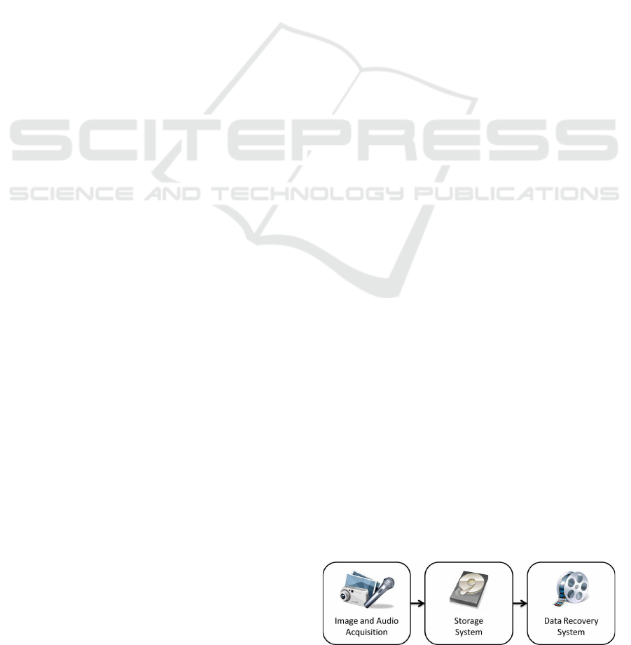
reconstruction system. Figure 1 shows a general
scheme of the developed system.
Figure 1: General scheme of the entire system.
The paper is organized as follows: The Image
and Audio Acquisition System is presented in Sec-
52
S. Siordia O., Martín de Diego I., Conde C. and Cabello E..
WIRELESS IN-VEHICLE COMPLAINT DRIVER ENVIRONMENT RECORDER.
DOI: 10.5220/0003567300520058
In Proceedings of the International Conference on Signal Processing and Multimedia Applications (SIGMAP-2011), pages 52-58
ISBN: 978-989-8425-72-0
Copyright
c
2011 SCITEPRESS (Science and Technology Publications, Lda.)

Figure 2: Scheme of the Image and Audio Acquisition System.
tion 2. The Storage and Data Recovery Systems are
described in Section 3 and 4 respectively. The results
and its discussion are presented in Section 5. Finally,
Section 6 concludes.
2 ACQUISITION SYSTEM
In this section, the Image and Audio Acquisition
System is detailed (see Figure 2). In this system,
the image and audio signals are acquired from the
real world for its processing. When an acquisition
has been done, the digitized audio and image data
is packed for its wireless transmission to the Storage
System.
As the first step of the acquisition process, it is
necessary to digitize image and audio signals from the
real world. As the project must be tested in several
kind of environments (i.e. cars, trucks, simulators,
etc.), it is very important to consider the adaptability
needed by the system. For this purpose, the Micron
R
MT9P031 digital image sensor was selected. This
highly configurable CMOS image sensor, allows the
acquisition of images with a resolution up to 5 Mp
(Mega pixels) at 14fps (frames per second). The main
features of this image sensor are (Micron, 2006):
• 12 bits Analog to Digital Converter.
• Pixel size of 2.2 µm
2
.
• Active pixels: 2592 X 1944.
• Up to 310 fps in low resolution (352 x 240).
• Extra programmable controls:
– gain, frame rate, resolution and exposure time.
The MT9P031 (shown in Figure 3), is provided
with an USB adapter that allows the acquisition of
digital images in any computer-based system.
The resolution of the acquired image could be
configured directly on the MT9P031 digital image
sensor. However, an image with a lower resolution
than the full one allowed by the sensor (5 Mp), is
Figure 3: Micron MT9P031 CMOS digital image sensor.
just a reduced version of the original image. In
order to generate the reduced image version, two
types of resolution reduction methods are supported
by this sensor (Micron, 2006): binning and skipping.
The binning method consists on the reduction of
the image resolution by averaging groups of pixels
converting them in a single value. This method is
able to improve the resultant image quality with a
noticeable better SNR (Signal to Noise Ratio). How-
ever, the time needed for the method for the averaging
calculations could reduce the frame rate drastically
depending on the image resolution configured by the
user. The skipping method consists on the reduction
of the image resolution by skipping information of the
original image when generating its reduced version.
This method, much faster than the first one, is used
to capture images without SNR improvement. Notice
that, in both methods, the field of view given by the
optics of the lens of the sensor is maintained since the
resultant image contains information of most of the
pixels of the original image. As any other common
CMOS image sensor, the images are acquired from
the real world through a Bayer filter that makes each
active pixel sensible to a specific wave length of one
of the three additive primary colors (Red, Green or
Blue)(Bayer, 1976). Figure 4 shows a representation
of the Bayer filter placed as a layer over the CMOS
sensor. After the acquisition of the image, and prior to
its compression, it is necessary to convert it from the
Bayer format to the RGB format (the most commonly
used format in computer vision (Paschos, 1999)). As
WIRELESS IN-VEHICLE COMPLAINT DRIVER ENVIRONMENT RECORDER
53
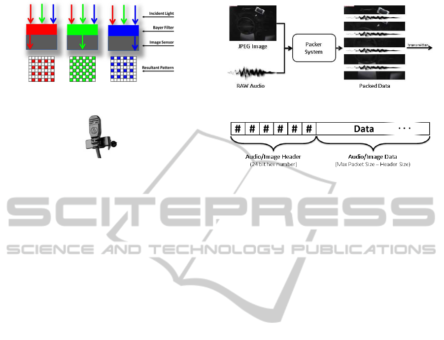
Figure 4: Bayer filter used in most CMOS image sensors.
Figure 5: Ambient microphone used for audio acquisition.
mentioned earlier, in the Bayer format, each active
pixel contains information of just one additive pri-
mary color (see Figure 4). However, in the RGB
format, each pixel must contain information of the
three primary additive colors. In order to complete
the color information of each pixel in a Bayer to
RGB conversion, it is necessary to interpolate the
missing values with the information provided by the
pixel neighborhood (Sakamoto et al., 1998). In this
case, the mean of the two nearest neighbors with
information about the missing color was considered.
Once an RGB image is obtained, the image compres-
sion is made using the JPEG standards that allows
a selectable compression quality to prevent critical
data loss (Wallace, 1991). Due to the adaptability
needed by the system, the image resolution, exposure
time and compression quality were left as user con-
figurable parameters to easily adapt the system to the
environment conditions. For the audio acquisition,
the signal recording from the real world was made
through a common ambient microphone of a small
size that could be conveniently located in any place
within the driver’s cab (see Figure 5). In the same
way, the quality parameters for the audio digitization
were left to the user to configure the system to meet
his needs. However, following the Nyquist criterion,
several tests made during the development of the
project suggest that an audio digitization at 8
′
000
samples per second with 8 bits per sample were
enough to meet the project purposes (see for instance
(Tropp et al., 2010)).
When an image and an audio segment has been
acquired, the data is delivered to the Packer System
for its preparation prior to its transmission (see Figure
2). The Packer System, shown in Figure 6, is
responsible of the alternation of the acquired data
for the successfully transmission of image and audio
information simultaneously to the Storage System.
Figure 6: Scheme of the packer system data flow.
Figure 7: Data packets generated by the Packer System.
The transmission protocol considered for this project
was the TCP/IP due to its facility to incorporate
new wireless devices in an in-vehicle complaint net-
work (Kwag and Lee, 2006);(Saravanan et al., 2009).
The TCP/IP transmission protocol is based on send-
ing data packets from a source device (the Image
and Audio Acquisition System) to a destination (the
Storage System). As the destination system will
be responsible of the storage of image and audio
information in different memories (see Figure 10),
the Packer System is in charge of the generation of
these data packets ensuring that each one contains
information of only one source (image or audio).
On the transmission process, each TCP/IP packet
is transmitted with a 24 bits header that denotes
the data content type (image data or audio data).
Notice that, due to the TCP/IP packet segmentation,
the image and audio headers must be selected as a
combination of values that could not appear in the
data at any time in normal conditions. An example
of a correct header combination could be #FFABBA
for images (following JPEG specifications (Wallace,
1991)) and #FFBAAB for audio (not allowing #FF
values on the digitization). Figure 7 shows the
scheme of a packet generated by the Packer System.
The maximum packet size was set to 1
′
024 bytes as
default to avoid IP segmentation (following TCP/IP
specifications (Clark, 1988)). However, it could
be configured by the user at any time to meet his
connection requirements.
Two versions of the Audio and Image Acquisition
System were developed in this work: a hardware
version using a Xilinx Virtex 5 FPGA (XC5VSX50T)
(see Figure 8) and a software version running on an
in-vehicle complaint computer system (see Figure 9).
The discussion and comparison of both versions will
be presented in Section 5.
SIGMAP 2011 - International Conference on Signal Processing and Multimedia Applications
54
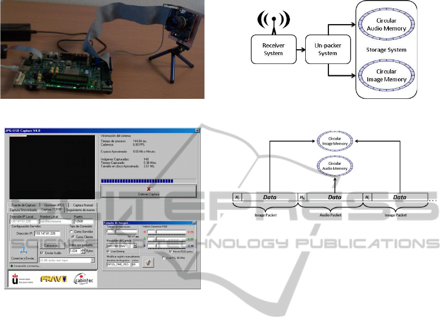
Figure 8: Image and Audio Acquisition System (hardware).
Figure 9: Image and Audio Acquisition System (software).
3 STORAGE SYSTEM
In this section, the Storage System is detailed. Figure
10 shows a general scheme and data flow of this
system. Image and audio information is wireless
received from the acquisition system as data packets.
The data is un-packed and stored in circular memories
depending on its content.
For the analysis of information in an accident
reproduction system, the data received from different
sources of information must be studied separately.
For that purpose, the data received from the Image
and Audio Acquisition System is stored in indepen-
dent memories. That is, one memory is used for the
storage of image data and other for the storage of
audio data. Further, as the information of interest
is centered at the prior and posterior instants to a
traffic accident, circular memories were considered to
reduce the storage cost of the system. As soon as a
packet is received trough the TCP/IP connection, its
data is delivered to the Un-packer System, which is in
charge of the data analysis and storage. Notice that,
as mentioned in Section 2, due to the possibility of
getting broken packets on the TCP/IP protocol, the
Figure 10: Scheme of the storage system.
Figure 11: Scheme of the un-packer system.
image and audio headers should be found in any
part of the received packets (not exclusively at the
beginning). Hence, to guarantee the reception of
a complete data packet, it is necessary to wait for
two consecutive image or audio headers and store the
intermediate data. Figure 11 shows the data analysis
made by the Un-packer system to select a target
memory for the received data. When a new packet
arrives, the image/audio header bits are discarded
and the data is stored in its corresponding circular
memory. Following the circular memory concept,
when the data reaches the maximum memory size,
the oldest data is replaced with the new one. The
maximum size of the circular memories could be set
by the user to meet his requirements at any time.
Notice that, the Image and Audio Acquisition
System and the Storage System share a set of pa-
rameters that must be configured for its compatibility.
Specifically, the image and audio headers and the
maximum packet size for the transmission protocol
must be the same. As a first approach in this ongoing
project, due to the reliability needed to effectively
store the received data, a software version of the
Storage System was considered. This version, devel-
oped to work under an in-vehicle complaint computer
system, allows image and audio reception trough a
common TCP/IP connection. The image and audio
data received in each packet is stored in two virtual
circular memories directly into the hard disk. The
graphical user interface of the software developed for
the Storage System is shown in Figure 12.
WIRELESS IN-VEHICLE COMPLAINT DRIVER ENVIRONMENT RECORDER
55
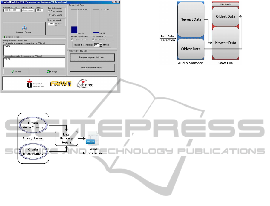
Figure 12: Storage System (software).
Figure 13: Scheme of the data recovery system.
4 DATA RECOVERY SYSTEM
In this section the Data Recovery System, shown in
Figure 13, is detailed. The data stored in the image
and audio circular memories is analyzed to recover
its information in the correct sequence. The infor-
mation recovered from the image and audio sources
could be merged to obtain a highly detailed scene
reconstruction. At this time, the image and audio
recovery algorithms were included in the Storage
System software to facilitate the tests of the entire
system along the development of the project (see
Figure 12).
The audio recovery process consists on the gen-
eration of a common audio header according to the
parameters configured for the audio digitization on
the Image and Audio Acquisition System. The data
recovered from the audio circular memory is used to
generate an audio file that could be easily reproduced
in any compatible device. Notice that, as shown in
Figure 14, the memory data must be reordered from
the oldest information stored to recover the correct
data sequence. The result of the audio recovery
process is a standard WAV file (Waveform Audio).
For the image recovery process, it is no necessary to
configure the parameters used at the image acquisition
stage since all the information is contained in the
Figure 14: Scheme of the audio recovery process.
headers of each image file. The recovery process must
look for the JPEG initial marker (#FFD8 following
JPEG standards (Wallace, 1991)) in a 16-bits search
along the image circular memory. As shown in
Figure 16, all the data found between two JPEG initial
markers should be saved as the data of the last image
file. As the JPEG image headers contains information
of the time and date in which they where acquired, the
data sequence could be easily recovered. The result of
the image recovery process is a set of ordered JPEG
images. Although each recovery algorithm could be
executed independently at any time by the user, as
shown in Figure 13, the resultant products of each
recovery process could be merged to generate a video
file containing all the information acquired from the
driver environment. Notice that, the time length of
the audio recovered may not be the same of the one of
the images recovered. If an exact match is required,
image and audio acquisition parameters as well as the
circular memory sizes must be set to obtain a similar
data rate.
5 RESULTS AND DISCUSSION
Several tests of the system were carried out in a highly
realistic truck simulator developed for the CABIN-
TEC project (Brazalez et al., 2008) (see Figure 15(a)).
The system was located over the steering wheel and
over the driver (see Figure 15(b)) to obtain cenital
images as shown in Figure 15(c).
First, for the Image and Audio Acquisition Sys-
tem, the software and hardware versions were com-
pared. As the communication between the Image and
Audio Acquisition Systems and the CMOS digital
image sensor is made by different physical connec-
tions (USB for the software version and IDE for
the hardware version), a benchmarking of the image
acquisition times was possible. Table 1, shows the
frame rate obtained for each system version at differ-
ent resolutions using different reduction methods. As
expected, the results of the comparison shows that the
SIGMAP 2011 - International Conference on Signal Processing and Multimedia Applications
56
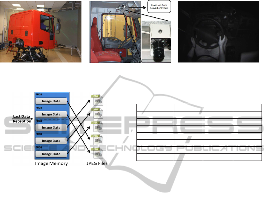
(a) CABINTEC truck simulator.
(b) Acquisition system location.
(c) Cenital images of the driver.
Figure 15: Tests of the system in a highly realistic truck simulator.
Figure 16: Scheme of the image recovery process.
hardware version obtains outstanding frame rates over
the software version in all the cases. Notice that, an
image acquisition process made at a high frame rate,
could help to the reconstruction of a more detailed
scene. However, the flexibility and low cost of the
software version is preferred in the earlier stages of
the ongoing project as it allows the image acquisition
from any Micron
R
CMOS image sensors attached to
the system or from any configured capture device.
On the other side, the hardware version is tied to
the MT9P031 CMOS image sensor for which it was
designed.
As the audio acquisition and digitization is made
at a constant rate (i.e. 8
′
000 Hz, 8 bits), a comparison
between the hardware and software versions was not
possible for this topic.
For the storage system it was found that circular
memories of 10 MB were enough to record up to
1
′
250 seconds of audio at the default quality (8’000
Hz, 8 bits) and up to 31 seconds of image sequences
with a VGA resolution at 10 fps. Several tests
reconstructing simulated traffic accidents suggest that
these time lenghts are enough to study the causes of
the most common traffic issues.
Table 1: Image and Audio Acquisition System comparison:
image acquisition frame rate (Hardware vs Software).
Size Mode FPS HW FPS SW
352× 240 - 302.11 174.82
352× 240 Skipping 302.11 174.82
640× 480 Binning 54.70 54.70
640× 480 Skipping 126.12 56.80
1280× 960 Binning 34.79 14.80
1280× 960 Skipping 45.18 14.80
2576× 1936 - 14.15 3.67
6 CONCLUSIONS
In this paper, an in-vehicle complaint environment
recorder has been presented. The system is divided in
an Image and Audio Acquisition System, an Storage
System and a Data Recovery System. All the systems
were designed to work under in-vehicle complaint
devices. The transmission protocol used for the
systems communications is compatible with most
wireless existent in-vehicle network architectures.
Several tests made in a very realistic truck simula-
tor show the reliability of the system while recording
and storing information related to the driving task.
Furthermore, detailed scene reconstructions of sim-
ulated traffic accidents show that the acquired data is
useful to study the main causes of traffic incidents.
Taking advantage of the existent in-vehicle tech-
nologies, a Bus CAN interface that allows the acqui-
sition of physical variables of the truck (i.e. speed,
acceleration, steering wheel angle, etc.) and the road
(i.e. maximum speed, inclination, traffic density, etc.)
is being developed. Promising results studying the
causes of traffic accidents are being obtained when
the data acquired by the system presented in this paper
(considering driver, vehicle and road information) is
used as input in a simulation tool called Virtual Co
Driver (Siordia et al., 2010).
In addition, a real time analysis of the driver’s
WIRELESS IN-VEHICLE COMPLAINT DRIVER ENVIRONMENT RECORDER
57

hands position is being developed to include a warn-
ing system based on the automatic detection of the
driver behavior (Crespo et al., 2010). This warning
system will be embedded in the recorder presented in
this work.
ACKNOWLEDGEMENTS
This work is supported by the Ministry of Science
and Innovation of Spain: CABINTEC: PSE-37010-
2007 and VULCANO: TEC2009-10639-C04-04, and
by the project ANOTA funded by the “C´atedra de
Ecotransporte, Tecnolog´ıa y Movilidad” from the
University Rey Juan Carlos.
REFERENCES
Bayer, B. E. (1976). Color imaging array, US Patent
3,971,065.
Brazalez, A., Delgado, B., Sevillano, M., Garca, I., and
Matey, L. (2008). CABINTEC: Cabina inteligente
para el transporte por carretera. In Proc. of
the Congreso Espa˜nol de Sistemas Inteligentes de
Transporte.
CABINTEC (2011). Cabintec: Intelligent cabin truck for
road transport. http://www.cabintec.net.
Chet, N. C. (2003). Design of black box for moving vehicle
warning system. In Research and Development, 2003.
SCORED 2003. Proceedings. Student Conference on,
pages 193 – 196.
Clark, D. D. (1988). The design philosophy of the darpa
internet protocols. In SIGCOMM, pages 106–114.
Crespo, R., de Diego, I. M., Conde, C., and Cabello, E.
(2010). Detection and tracking of driver’s hands in
real time. In Bloch, I. and Cesar, R. M., editors,
CIARP, volume 6419 of Lecture Notes in Computer
Science, pages 212–219. Springer.
Dingus, T. A., Klauer, S., Neale, V. L., Petersen, A.,
Lee, S. E., Sudweeks, J., Perez, M. A., Hankey, J.,
Ramsey, D., Gupta, S., Bucher, C., Doerzaph, Z. R.,
Jermeland, J., and Knipling, R. (April 2006). The
100-car naturalistic driving study. Technical report,
Virginia Tech Transportation Institute, NHTSA.
Jiang, L. and Yu, C. (2010). Design and implementation
of car black box based on embedded system. In
Electrical and Control Engineering (ICECE), 2010
International Conference on, pages 3537 –3539.
Jung, S. M. and Lim, M. S. (2007). System on chip
design of embedded controller for car black box. In
Information Technology Convergence, 2007. ISITC
2007. International Symposium on, pages 217 –221.
Kassem, A., Jabr, R., Salamouni, G., and Maalouf, Z.
(2008). Vehicle black box system. In Systems
Conference, 2008 2nd Annual IEEE, pages 1 –6.
Khanapurkar, M., Bajaj, P., and Gharode, D. (2008). A
design approach for intelligent vehicle black box
system with intra-vehicular communication using
lin/flex-ray protocols. In Industrial Technology, 2008.
ICIT 2008. IEEE International Conference on, pages
1 –6.
Kwag, S.-J. and Lee, S.-S. (2006). Performance
evaluation of ieee 802.11 ad-hoc network in vehicle
to vehicle communication. In Proceedings of the
3rd international conference on Mobile technology,
applications & systems, Mobility ’06, New York, NY,
USA. ACM.
Micron, T. (2006). MT9P031 - CMOS digital image
sensor data sheet. (www.aptina.com) (rev. feb. 2011).
http://www.aptina.com.
Paschos, G. (1999). A color space performance comparison
in the processing of color textured images: Rgb vs.
l*a*b*. In PICS, pages 200–203. IS&T - The Society
for Imaging Science and Technology.
Sakamoto, T., Nakanishi, C., and Hase, T. (1998). Software
pixel interpolation for digital still cameras suitable
for a 32-bit mcu. Consumer Electronics, IEEE
Transactions on, 44(4):1342 –1352.
Saravanan, K., Arunkumar, T., and K., R. (2009). A mid-
dleware architectural framework for vehicular safety
over vanet invanet. Networks & Communications,
International Conference on, 0:277–282.
Siordia, O. S., de Diego, I. M., Conde, C., Reyes, G., and
Cabello, E. (2010). Driving risk classification based
on experts evaluation. In Proceedings of the 2010
IEEE Intelligent Vehicles Symposium (IV ’10), pages
1098–1103.
Trezise, I., Stoney, E., Bishop, B., Eren, J., Harkness,
A., Langdon, C., and Mulder, T. (2006). Report of
the road safety committee on the inquiry into driver
distraction. Road Safety Committee, Parliament of
Victoria, Melbourne, Victoria, Australia.
Tropp, J., Laska, J., Duarte, M., Romberg, J., and Baraniuk,
R. (2010). Beyond nyquist: Efficient sampling of
sparse bandlimited signals. Information Theory, IEEE
Transactions on, 56(1):520–544.
Wallace, G. K. (1991). The jpeg still picture compression
standard. Communications of the ACM, pages 30–44.
Wang, J. S., Knipling, R. R., and Goodman, M. J.
(1996). The role of driver inattention in crashes;
new statistics from the 1995 crashworthiness data
system. Proceedings of 40th Annual meeting of
the Association for the Advancement of Automotive
Medicine.
SIGMAP 2011 - International Conference on Signal Processing and Multimedia Applications
58
