
Backward Requirements Traceability within the
Topology-based Model Driven Software Development
Erika Asnina, Bernards Gulbis, Janis Osis, Gundars Alksnis,
Uldis Donins and Armands Slihte
Department of Applied Computer Science, Institute of Applied Computer Systems
Riga Technical University, Meza iela 1-k.3, LV-1048, Riga, Latvia
Abstract. The inconsistence between software and specifications leads to
unpredictable side effects after change implementation. Impact analysis may be
useful here, but manual control of trace links is very expensive. Model Driven
Architecture and automated transformations should make the impact analysis
easier. The issue is that the impact analysis of changes in software to real world
functional units is intuitive. Formalization of specifications of the environment
and software functionality as well as their analysis by means of Topological
Functioning Model extends possibilities of the impact analysis. This paper
demonstrates the establishment of formal trace links to real world functional
units and entities from user requirements and analysis artifacts. These links
show element interdependence explicitly, and, hence, make the impact analysis
more thorough.
1 Introduction
A software system is a subject to non-stop changes; otherwise it becomes less and less
useful for its initial purpose (as cited in Yang & Ward, 2002). Frequent change
implementations lead to breaking structure of the software system and appearance of
unpredictable side effects. Impact analysis is devoted to assess side effects and
estimate change implementation costs.
This paper discusses application of functional and topological properties of
Topological Functioning Model (TFM) for impact analysis within Object
Management Group’s (OMG) Model Driven Architecture (MDA). This research
continues research presented in [8], [12], [11], [2] and [3].
The paper is organized as follows. Section 2 briefly discusses the impact of
changes on MDA models. The related work also is discussed here. Section 3 describes
and illustrates how the suggested formalization can be applied for the impact analysis.
Section 4 demonstrates the proposed idea by the example of a library system.
Conclusion discusses results and future research directions.
Asnina E., Gulbis B., Osis J., Alksnis G., Donins U. and Slihte A..
Backward Requirements Traceability within the Topology-based Model Driven Software Development.
DOI: 10.5220/0003578500360045
In Proceedings of the 3rd International Workshop on Model-Driven Architecture and Modeling-Driven Software Development (MDA & MDSD-2011),
pages 36-45
ISBN: 978-989-8425-59-1
Copyright
c
2011 SCITEPRESS (Science and Technology Publications, Lda.)
2 Traceability, Changes and Model Driven Architecture
As [5] wrote “requirements traceability is an ability to follow the life of a
requirement”. They distinguished pre-RS (backward) and post-RS (forward)
traceability. Pre-RS traceability refers to requirement’s life prior to its inclusion in the
requirements specification. Post-RS traceability refers to requirements life from the
moment of its inclusion in the requirements specification.
One of the main issues in traceability practice is the high cost of manual control of
traceability information [1]. In case of correct and entire implementation of the idea
and principles of MDA, impact analysis and traceability could be automated and
describe the state of the software system completely and clearly in always up-to-date
documentation – software system models.
MDA includes a computation independent model (CIM), a platform-independent
model (PIM) and a platform-specific model (PSM). They model systems at different
levels of abstraction. Besides them, additional models may also be used, e.g. a
transformation model, a traceability model, a platform model, a database
model/scheme, and so on. In case of automated transformations, the traceability
model with explicit trace links can be created and maintained automatically.
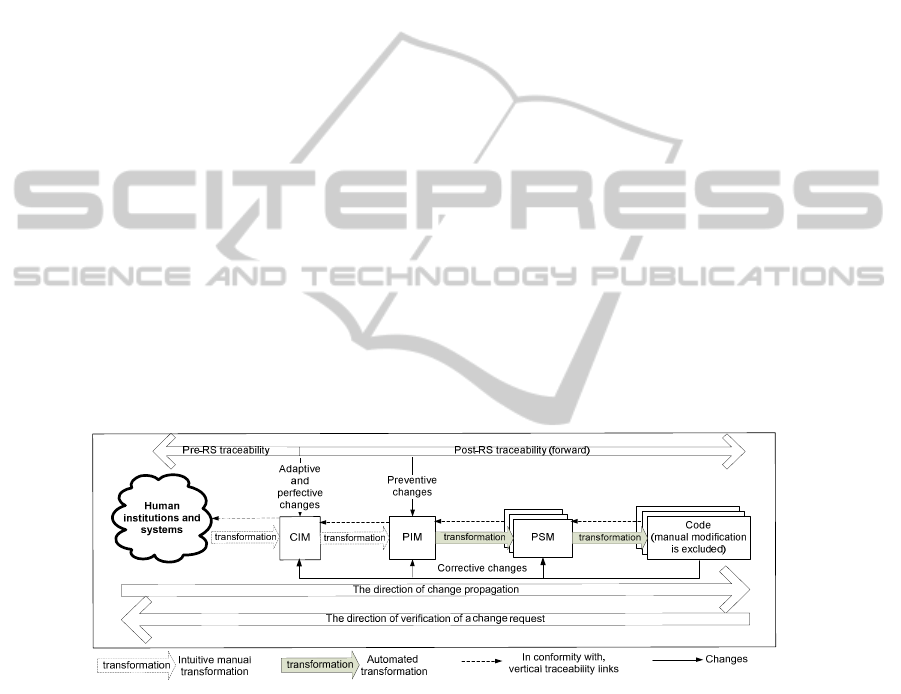
Let us consider the categories of changes - corrective, adaptive, perfective and
preventive [14]- in the framework of MDA (Fig. 1). Here, we have limited models
with the CIM, PIM, PSM, code and transformations. Adaptive and perfective changes
should be first verified and implemented in the CIM, and only then propagated to PIM
to PSM to code. Preventive changes affect software design already specified in the
PIM; therefore, they must be verified on compliance with the CIM and propagated
from [CIM to] PIM to PSM to code. In turn, corrective changes can affect every
MDA model.
Fig. 1. Categories of changes and their impact on MDA models.
In general, if incompliance is located in the requirements specification,
modifications start from the CIM and are propagated to code through PIMs and
PSMs. Post-RS traceability information is kept together with transformations (that are
to be automated starting from the PIM level) and helps in change requests verification
and change cost estimation. However, it does not help in identifying the origin (and
production) of requirements.
37

The current literature contains ample publications describing support of post-RS
traceability, rather manually defined than defined by using heuristic traceability rules
in the stage from requirements (CIM) to analysis models (PIM). However, most
approaches lack support of pre-RS traceability (within CIM). Problems confronting
pre-RS traceability are enumerated in detail in [5].
Pre-RS traceability includes a documented history of eliciting the final
requirements from a pre-requirements set [6], as well as a stakeholder aspect, which is
oriented on dependencies between high-level stakeholders (as well as organizations,
system missions, standards) as a starting point for driving and documenting
requirements process [13]. However, MDA either considers the CIM only as informal
(textual) requirements model without its relating to business and knowledge models
(thus, the high-level stakeholder aspect is often skipped), or uses traditional
requirements engineering models/languages.
A very ambient overview on recent publications about requirements generation
from software engineering models (and thus possibility to trace their origin) is
performed by [7]. Software models used are KAOS, i*, and temporal logic goal-
oriented models, RAD business models, eEPC business models as well as use cases
and scenarios, UML models and user interface. Models are ordered by the decreasing
number of applications. As the authors concluded, the better way is to use natural and
formal languages together. High-level business process models in BPMN notations
and their transformations also can be used [4].
Summarizing, such issues as a lack of conformity to complex human institutions
and systems and misunderstanding of the system’s purpose between developers and
users of the software system requires the pre-RS traceability. There must be up-to-
date formal models that contain knowledge about the “real world” domain at the
computation independent level in MDA. Moreover, system requirements must be
traceable, i.e., in strong conformity with these formal models. This allows at least
predicting, and at most avoiding, side effects of change implementations.
3 Changes and Requirements Traceability within Topology-based
MDA Lifecycle
The Topological Functioning Model, TFM, is a formal mathematical specification of
domain functioning. Its mathematical foundations, topological and functioning
properties, are described in detail in [10]. The TFM introduces modification in the
beginning of MDA development life-cycle [8]– in the CIM. It captures business
knowledge about the problem domain, i.e. business functional characteristics and
cause-effect relations among them, organizational units/roles and their responsibility
for providing and using those functional characteristics, and domain objects and their
participation in business functioning [10]. The TFM is a ground for checking
compliance of users’ and software functional requirements to the problem domain [9].
Fig. 2 illustrates the formalized part of MDA software development lifecycle, the
CIM, by means of the TFMs of the business system and information system.
The TFM of the business system (BS) formally specifies functionality of the
human institution or system. In turn, the TFM of the information system (IS) formally
specifies functionality of the computer system within that BS. Models of BS and IS
38
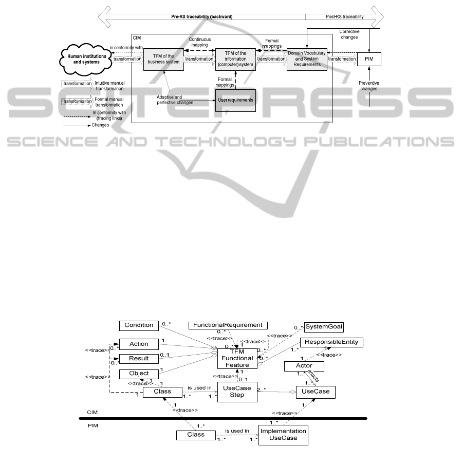
are continuously mapped, i.e., they are formally interrelated, and all changes must be
specified in both models. Transformation and traceability between these models is
formal and based on continuous mapping of graphs [2].
Fig. 2 points to the fact that construction of the TFM is a manual activity that
transforms informal verbal descriptions to the formal mathematical specification. The
construction of the TFM is described at large in [10]. However, first positive results
of the on-going research on automation of this activity by using a natural language
processing system are demonstrated in [12].
Fig. 2. Changes and requirements traceability at the beginning of topology-based MDA
software development lifecycle.
Initially, models of BS and IS are equal. Verification of user requirements
(desires) based on formal mappings from them to this initial TFM of IS results in
checking and correcting requirements as well as refining and modifying the TFM of
IS, while keeping its formal consistency with the TFM of BS. Then formal derivation
of software functional requirements as well as entities (classes) in domain vocabulary
becomes possible.
Another manual activity demonstrated in Fig. 2 is the transformation from CIM to
PIM, i.e., from domain vocabulary and system requirements to analysis models of the
system. The initial results of the on-going research on formalization of this activity by
means of the TFM are illustrated in [11]. Even these first results show that formal
tracing from the TFM of IS, domain vocabulary and software functional requirements
to the analysis model is possible.
Fig. 3. Pre-RS traceability framework in general.
39

A general Pre-RS traceability framework is illustrated in Fig. 3. Classes at the
conceptual level, actors and use cases (as software functional requirements),
functional requirements and system goals set by users (users’ desires) are traced to
TFM functional features, traceability between which at different levels of abstraction
is also provided. Hence, it is possible to determine why a class or a requirement is
included in the software solution, and how it is linked with other structural or
behavioral elements by using the formal ground – formally related topological models
of business and information system functionality.
4 Pre-RS Traceability in Case of the Perfective Change Request
For illustration of advantages of the introduced formalism, let’s take a little bit
simplified example that describes an information system of the library “Library IS”.
4.1 The CIM – Business Model
The TFM of BS (The Library)
is presented in Fig. 4a. Description of functional
features (FFs) is given in the form “identifier: feature_description, precondition,
responsible_entity (where, “Lib” denotes “librarian”, and “R” denotes “reader”)” and
they are as follows: 1: Arriving [of] a person, {}, person; 2: Creating a reader
account, {unregistered person}, Lib; 3: Creating a reader card, {}, Lib; 4: Giving out
the card to a reader, {}, Lib; 5: Indentifying a reader, {}, Lib; 6: Completing the
request for a book, {}, R; 7: Registering the request for a book, {}, Lib; 8: Taking out
the book copy from a book fund, {a book copy is available}, Lib; 9: Checking out the
book copy for a reader, {}, Lib; 10: Giving out the book copy to a reader, {}, Lib; 11:
Getting a book copy, {}, R; 12: Returning a book copy, {}, R; 13: Taking back the
book copy from a reader, {}, Lib; 14: Checking the term_of_loan of a book copy, {},
Lib; 15: Evaluating the condition of a book copy, {}, Lib; 16: Imposing a fine, {the
term_of_loan is exceeded or the condition is damaged}, Lib; 17: Returning the book
copy to a book fund, {}, Lib; 18: Paying a fine, {imposed fine}, R; 19: Closing a fine,
{paid fine}, Lib; 20: Completing a statement_of_destruction, {hardly damaged book
copy}, Lib; 21: Sending the book copy to a destructor, {}, Lib; 22: Destructing a
book copy, {}, Destructor.
User Requirements (Functional)
are dedicated to receiving an IS that supports
servicing readers. They are the following - FR1: The system shall register a new
reader; FR2: The system shall check out a book copy; FR3: The system shall handle
return of a book copy; FR4: The system shall account reader’s fines.
Tracing: The requirements map onto FFs of the TFM of BS as follows (Fig. 4b): FR1
to {2, 3, 4}, FR2 to {5, 7, 8, 9}, FR3 to {5, 13, 14, 15, 17}, and FR4 to {16, 19}.
The TFM of IS
is illustrated in Fig. 5a. After formal identification of the IS, a
subsystem of the BS, it excludes only two functional features - 21 and 22.
System Goals to is Set by Users
are needed for TFM decomposition into use cases.
The goals are stated as follows: SG1 “Register a reader”, SG2 “Check out a book”,
40

SG3 “Return a book”, SG4 “Pay a fine”, SG5 “Impose a fine”, and SG6 “Close a
fine”. All system goals are set by the librarian.
Fig. 4. The TFM of Business System (a) and mappings from user requirements to it (b).
Fig. 5. The TFM of Information System (a) and mappings from system goals to it (b).
Tracing: The mappings from the TFM of IS to corresponding FFs of the TFM of BS
are one-to-one. The mappings from system goals to the TFM of IS are illustrated in
Fig. 5b. Thus, SG1 “Register a reader” can be achieved by execution of functional
features 2, 3, and 4; in turn, SG2 “Check out a book” – by 5, 6, 7, 8, 9 and 10, SG3
“Return a book” by 5, 13, 14, 15, 16, and 17, SG4 “Pay a fine” by 5, 18 and 19, SG5
“Impose a fine” by 16, and SG6 “Close a fine” by 19.
SG1 corresponds to FR1, SG2 to FR2, and SG3 to FR3. In turn, SG4, SG5 and SG6
together correspond to FR4. However, functionality specified by FFs 6, 10, and 18
belongs to the IS as such, but it is excluded from the software system, i.e., it will
remain manual. Besides that, functional features 1 and 12 indicate on the input data
from the BS to the IS; and features 11 and 20 indicate on the output data that the IS
provides for other activities of the BS and its external environment.
4.2 The CIM – Business Requirements for the System
Domain Vocabulary and System Requirements
, a conceptual class diagram and a use
case model, are represented in Fig. 6a. The classes are driven from the TFM of IS.
They are ReaderAccount, ReaderCard, Reader, Request, BookCopy, BookFund, and
Fine. The detailed description of class properties is skipped here.
The diagram and descriptions of use cases are also derived from the TFM of IS by
using system goals as a decomposition criteria and mappings from functional
requirements as criteria for determination of use case flows. The use cases activated
by an actor “Librarian” are “Register reader”, “Identify reader”, “Check out book”,
“Return book” and “Close fine”. “Identify reader” is an inclusion use case.
41
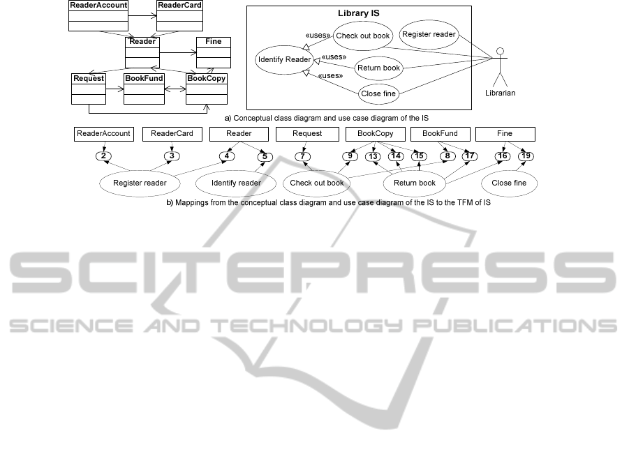
Fig. 6. The conceptual class diagram and use case diagram (a), and their mappings to functional
features of the TFM of IS (b).
Tracing: Mappings from the classes and use cases to the TFM of IS are illustrated in
Fig. 6b. As we can infer, “Register reader” operates with classes ReaderAccount,
ReaderCard, and Reader. “Indentify reader” operates with Reader. “Check out
book” operates with RequestForBook, BookCopy, and BookFund. “Return book”
operates with BookCopy, BookFund, and Fine. Both “Impose fine” and “Close fine”
operate with Fine. Thus, possible changes of classes Reader, BookCopy, BookFund
and Fine may have impact on several interrelated functional units. Main and
alternative flows of use cases should also be defined in strong compliance with the
functional features. We omit system sequence diagrams here due to page limitation.
4.3 Illustration of Traceability Links in Case the Change Request Occurred
Let us consider the case of a perfective change request, i.e., changes in user
requirements. Let us assume that requirement “FR2: The system shall check out a
book copy” is extended to “FR2: The system shall allow a reader to complete and
register his/her request via Internet. The system shall perform check out a book copy
by the registered request by both reader and librarian. The system shall inform a
reader about the status of the registered request via e-mail.”
The trace links among elements before a modification are the following: FR2 is
linked with FFs 5, 7, 8, and 9 (Fig. 4b), which are linked with the system goal SG2
(Fig. 5b). Considering these FFs within the TFM of IS (Fig. 5a) shows that
functionality touched by the modification (see Fig. 7a) depends on FFs 2 and 3 (new
reader registration), 6 (completing the request for a book) and 17 (taking the
requested book copy from the book fund). Besides that, it affects FFs 10 (giving out
the book copy to a reader), 13 (taking back the book copy from a reader) and 18
(paying the fine). This means that the requested change may generate side effects in
these functional parts which origin from different user requirements and belong to
different system goals (Fig. 7b) and use cases – “Identify reader” and “Check out
book” (Fig. 6b). Hence, cause-effect relations between these functional features and
modified/new functionality must be carefully verified.
42
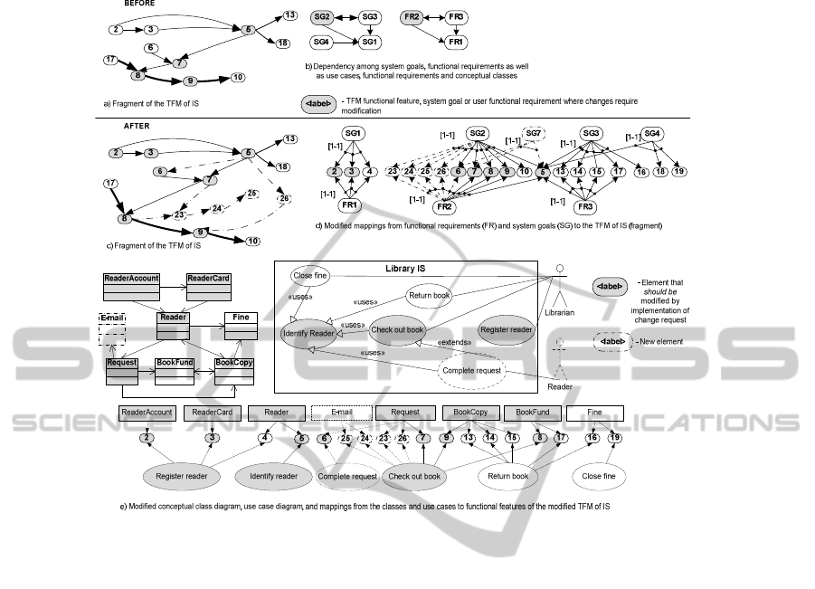
Fig. 7. Trace links between elements after change verification.
The TFM shows that completing of a book request is manual. First, the librarian
identifies a reader. Then the reader is allowed to complete the request manually, and
only after that the librarian registers the request. Thus, one part of the new FR2 is
already specified by feature 6. However, the new execution order adds a new path: the
reader provides his login data; if the reader is identified by the system, he is able to
complete an electronic request form and register it in the system. Hence, features 5
and 7 must be modified; the new cause-effect relation from feature 5 to 6 must be
established (Fig. 7c). The next point is that identification of a reader via Internet will
modify also the class Reader (Fig. 6b), e.g., by adding new class properties – login
name and password, and e-mail, as well as functionality of the use case “Register
reader” specified by features 2 and 3.
Another point is that a reader who has registered his/her request via Internet
should be notified about the request status. Hence, new FFs - “23: Updating the status
of the request of a reader, {the request is registered OR the book copy is taken from
the book fund}, System“, “24: Creating an e-mail, {}, System”, and “25: Sending the
e-mail to a reader, {}, System” - and cause-effect relations from features 7 and 8 to
23, from 23 to 24, and from 24 to 25 are established (Fig. 7c). Additionally, the new
class E-mail also is created (Fig. 7e).
Besides that, giving out a book copy should also be modified, since a reader can
came to the library to receive the book already taken from the fund. Checking out the
43

book copy (feature 9) should also be related to the mentioned Internet functionality.
Hence, a new feature is created – “26: Checking the status of the request of a reader,
{}, Librarian” that generates feature 9 only if the book copy has been taken from the
fund. A new alternative path in the TFM of IS is “5-26-9” (Fig. 7c).
Modifications of the TFM of IS must be propagated to the lower artifacts. Using
use cases requires verification of the system goals. The reader states a new goal SG7
“Complete the request via Internet” that includes features 5, 6 and 7. SG2 is extended
and includes also features 23, 24, 25 and 26 (Fig. 7d). This modifies conceptual class
and use case diagrams as shown in Fig. 7e. A new use case “Complete request” is
specified. It extends “Check out book” and includes “Identify reader”.
Summarizing, the change in FR2 requires modifications in FR1 and FR3 that will
cause creation of class E-mail and use case “Complete request”, modification of
classes ReaderAccount, ReaderCard, Reader, Request and use cases “Register
reader”, “Check out book” and “Identify reader”. Use cases “Return book” and
“Close fine” may require re-testing.
5 Conclusions
MDA gives new breath to post-RS traceability support. However, automated support
of pre-RS traceability requires formalization of requirements, business, knowledge
models and relations among them. The TFM as a formal CIM-Business Model gives
an opportunity to establish and use trace links between elements of development
artifacts for pre-RS traceability needs. This results in feasibility to trace system
requirements to and verify them with business functionality and original user
requirements, check necessity of modification of logically related parts, and propagate
established modifications in business models to system requirements and classes.
Direction of our on-going and further research is formalization of transformations
between CIM models and from CIM to PIM by means of topological functioning
modeling and “lightweight” mathematics.
References
1. Aizenbud-Reshef, N., Nolan, B. T., Rubin, J., & Shaham-Gafni, Y. (2006). Model
traceability. IBM SYSTEMS JOURNAL , 45 (3), pp. 515-526.
2. Asnina, E., & Osis, J. (2010). Computation independent models: bridging problem and
solution domains. Proceedings of the 2nd InternationalWorkshop on Model-Driven
Architecture and Modeling Theory-Driven Development MDA & MTDD 2010, In
conjunction with ENASE 2010, Athens, Greece, July 2010 (pp. 23-32). Portugal:
SciTePress.
3. Asnina, E., & Osis, J. (2011). Topological Functioning Model as a CIM-Business Model. In
J. Osis, & E. Asnina, Model-Driven Domain Analysis and Software Development:
Architectures and Functions (pp. 40-64). Hershey, New York, USA: IGI Global.
4. De Castro, V., Marcos, E., & Vara, J. M. (2011). Applying CIM-to-PIM model trnsforma-
tions for the service-oriented development of information systems. Information and
Software Technology , 53, 87-105.
44

5. Gotel, O. C., & Finkelstein, A. C. (1994). An Analysis of the Requirements Traceability
Problem. Proceedings of the First International Conference on Requirements Engineering,
1994 (pp. 94 - 101). Colorado Springs, CO , USA: IEEE.
6. Grammel, B., & Kastenholz, S. (2010). A Generic Traceability Framework for Facet-based
Traceability Data Extraction in Model-driven Software Development. Proceedings of the
6th ECMFA Traceability Workshop (ECMFA-TW), June 15th 2010, Paris, France (pp. 7-
14). ACM Press.
7. Nicolás, J., & Toval, A. (2009). On the generation of requirements specifications from
software engineering models: A systematic literature review. Information and Software
Technology , 51, 1291–1307.
8. Osis, J. (2006). Formal Computation Independent Model within the MDA Life Cycle. (P.
Loucopoulos, & K. Lyytinen, Eds.) International transactions on system science and
applications , 1 (2), pp. 159-166.
9. Osis, J., & Asnina, E. (2008). A Business Model to Make Software Development Less
Intuitive. Proceedings of 2008 International Conference on Innovation in Sofware
Engineering (ISE 2008). December 10-12, 2008, Vienna, Austria (pp. 1240-1245). IEEE
Computer Society Publishing.
10. Osis, J., & Asnina, E. (2011). Topological Modeling for Model-Driven Domain Analysis
and Software Development. In J. Osis, & E. Asnina, Model-Driven Domain Analysis and
Software Development: Architectures and Functions (pp. 15-39). Hershey, New York,
USA: IGI Global.
11. Osis, J., & Donins, U. (2010). Formalization of the UML Class Diagrams. In Evaluation of
Novel Approaches to Software Engineering (pp. 180-192). Berlin: Springer-Verlag.
12. Osis, J., & Slihte, A. (2010). Transforming Textual Use Cases to a Computation
Independent Model. Proceedings of the 2nd InternationalWorkshop on Model-Driven
Architecture and Modeling Theory-Driven Development MDA & MTDD 2010, In
conjunction with ENASE 2010, Athens, Greece, July 2010 (pp. 33-42). Portugal:
SciTePress.
13. Sahraoui, A.-E.-K. (2005). Requirements traceability issues: generic model, methodology
and formal basis. International Journal of Information Technology & Decision Making , 4
(1), 59-80.
14. Yang, H., & Ward, M. (2002). Successful Evolution of Software Systems. Boston, London:
Artech House, Incorporated.
45
