
INTEGRATING SYSML WITH SIMULINK USING
OPEN-SOURCE MODEL TRANSFORMATIONS
Andrea Sindico
1
, Marco Di Natale
2
and Gianpiero Panci
1
1
Research and Advanced Systems Design dpt., Elettronica S.p.A., Rome, Italy
2
ReTis Lab. TECIP Center, Scuola Superiore S. Anna, Pisa, Italy
Keywords: SysML, Simulink, Model Transformation, MDA.
Abstract: The realization of an integrated and automated modelling flow and tool framework joining OMG (i.e. UML,
SysML, etc.) and Mathworks (i.e. Matlab, Simulink, etc.) models and technologies is a very attractive
perspective because of the possibility of complementing their capabilities and strenghts. In this paper we
describe our project for an integrated flow and our initial results, consisting of a transformation workflow to
automatically generate Simulink models from SysML models and viceversa. Our proposed process is
compliant with the OMG Model Driven Architecture. The transformations have been realized using the
TopCased open-source modeling tool and the Acceleo model-to-text generator.
1 INTRODUCTION
Model Driven Engineering (Schmidt, 2006) is a term
encompassing all system engineering approaches
focused on models definition and exploitation. These
approaches are, in principle, meant to increase
productivity by:
maximizing compatibility among systems (via
reuse of standardized models);
simplifying the process of design (via models
of recurring design patterns); and
promoting communication among individuals
and teams working on the system (via a
standardization of the terminology and best
practices).
In agreement with most modern development
methodologies (Schmidt, 2006; Nicolescu,
Mosterman, 2009; MDA), MDE recognizes system
development as a staged effort, in which a set of
required functions, defined in an abstract or Platform
Independent Model (PIM) are deployed, possibly
automatically, onto an executable architecture.
The result of this deployment is a Platform
Specific Model (PSM).
PIM models are closer to specifications and can
be used for system-level functional decomposition
and the abstract verification of functional properties.
PSM models account for resource usage and can be
used for quantitative analysis of performance,
resource usage verification and planning.
PSM can finally represent the source for the
possible automatic generation of a code
implementation, documentation and other valuable
artifacts.
Despite general consensus on the MDE
objectives and continuous effort by the OMG in the
development of modeling standards and by tool
vendors in the support of the languages, quite often
models are only used as a pictorial representation of
requirements or functionalities.
Verification or, in general, analysis of properties
and especially automatic generation of
implementations are far from being widespread.
At now we can identify two major trends in
MDE: Model Based Design (MBD) (Nicolescu,
Mosterman, 2009) and Model Driven Architecture
(MDA). Although they share objectives and
principles they also present differences in the
adopted approaches and technologies so that they are
eventually considered competing or alternative.
The Model Driven Architecture (MDA) is an
OMG standard aimed at defining a reference
architecture for a design and development process
strongly based on the construction and analysis of
models.
The term Model-Based Design (MBD)
(Nicolescu, Mosterman,2009) instead indicates a
slightly different approach based on a different set of
models and tools. While MDA originated from the
move of a fundamentally software-oriented
45
Sindico A., Di Natale M. and Panci G..
INTEGRATING SYSML WITH SIMULINK USING OPEN-SOURCE MODEL TRANSFORMATIONS.
DOI: 10.5220/0003593600450056
In Proceedings of 1st International Conference on Simulation and Modeling Methodologies, Technologies and Applications (SIMULTECH-2011), pages
45-56
ISBN: 978-989-8425-78-2
Copyright
c
2011 SCITEPRESS (Science and Technology Publications, Lda.)

community (object-oriented design) towards system-
level modeling and embedded systems development,
MBD is very popular in the development of control-
oriented functions and originated from the domain of
control engineering and systems engineering. As
such, MBD languages are usually based on a
restricted but formal syntax and semantics, with an
underlying Model of Computation (MoC) based on
mathematical rules.
A Synchronous reactive semantics is the
foundation of the most popular tools such as
Simulink and SCADE (Benveniste, Caspi, Edwards
et al. 2003). MBD models are executable and can be
simulated. Verification of properties is made
possible by the use of a formal MoC and a path to
the automated generation of code is not only
possible, but has become common practice in the
automotive and aeronautics industry.
As a result, the two modeling frameworks tend to
appeal to people with a different technical
background. System analysts, System architects and
Software developers are typically more familiar with
modeling languages such as SysML (Hause, 2006)
or UML, which are part of the MDA approach.
Hardware, Firmware or Control engineers typically
prefer the executable models of Matlab and
Simulink, with their capabilities for simulation, code
generation and test coverage analysis, which are
instead part of the MBD approach. Indeed, the two
approaches might be combined to leverage their
strengths.
SysML modeling may be used at the
architecture-level to define the system
decomposition, the communication among
subsystems, the execution platform, including the
computation devices and the communication media
that are available, and the deployment of the
functional model into the execution architecture,
which requires the creation of an intermediate
software architecture model exposing and detailing
the task and message architecture.
Simulink models are to be preferred for the
modeling of the internal behavior of blocks and for
the maturity of the associated code generators when
producing the software or firmware implementation
of a complex function.
Indeed, it is commonly accepted (Vanderperern,
Dehaene, 2006; Deutsche Bank,2005; ESL Now
Survey, 2005; Electronics Eekly & Celoxica, 2005)
that future trends in model engineering will
encompass the definition of integrated design flows
exploiting complementarities between UML or
SysML and Matlab.
The combination of the two models requires the
capability of model-to-model transformations and
integration of heterogeneous models.
These operations are today often performed by
hand, motivated by the fact that proprietary
modeling languages, such as Simulink, lack a
publicly available meta-model (Vanderperern,
Dehaene, 2006).
However, manual transformations should be
avoided whenever possible since:
errors could be introduced during the
transformation process;
the target model could not actually conform to
the source model because of subjective
erroneous interpretations of the source model.
In this Paper we describe the first results of an
ongoing work aimed at defining a design and
development process of embedded systems based on
automatic transformations between SysML and
Simulink models.
The paper consists of the following sections:
in the II section we provide a brief summary of
what are the currently available works in
literature related to the integration of SysML
with Mathworks technologies (i.e. Matlab,
Simulink);
in the III section we provide a description of the
Model Driven Architecture and Model Based
Design frameworks;
in the IV section we provide a brief description
of SysML and Simulink languages;
in the V section we provide a description of our
model driven design and development process
which is centered on SysML to Simulink
transformations;
in the VII and VIII sections we finally provide
two examples aimed at showing how the
proposed transformation can be exploited to
automatically get simulink models from
SysML specifications.
The first example we propose is based on a
SysML model defined in (Hause, 2006).
We wanted to present the same example just to
proove our approach can be applied to already
existing models without particularly assumptions
about their characteristics.
We therefore propose another example with a
simplicistic model of one class of products our
Company, Elettronica S.p.A., designs and produces.
With this second example we would like to show
how the presented approach can be also exploited to
manage the design of systems in actual industrial
process.
SIMULTECH 2011 - 1st International Conference on Simulation and Modeling Methodologies, Technologies and
Applications
46

2 STATE OF THE ART AND
CONTRIBUTIONS
The match of a functional and execution architecture
is advocated by many in the academic community,
examples are the Y-cycle (Kienhuis, Deprettere, van
der Wolf et al. 2002) and the Platform-Based Design
PBD (Sangiovanni-Vincentelli, 2007), and in the
industrial domain, the AUTOSAR automotive
standard is probably the most relevant recent
example (AUTOSAR), as a way of obtaining
modularity and separation of concerns between a
functional specification and its implementation on a
target platform.
The OMG with the MDA has proposed a staged
development process in which a PIM is transformed
into a PSM.
In reality, however, very few examples still exist
for the application of the proposed methodology to
the design and development of complex
functionalities in actual systems.
As for the model-to-model transformations and
heterogenous models integration, a number of
approaches, methods, tools and case studies have
been proposed. Several approaches, such as the
GME (Karsai, 2003) and Metropolis (Balarin, 2002),
propose the use of a general metamodel as an
intermediate target for the integration of models. To
this end, the Eclipse modeling framework provides
support for metamodel specifications through its
Ecore meta-meta-modeling language.
Model-to-model transformation engines are
available for the Eclipse environment including ATL
and QVT (EMP).
Although Mathworks’ languages and
technologies (i.e. Matlab, Simulink, etc.) have
become a de facto standard for modeling the
analytical aspects of a system, there is still a lack of
automation in the way they can be integrated in a
more high level modeling framework, such as
SysML, devoted to the modeling of the whole
architecture of a system.
Vanderperren and Dehaene (2006) provide a
short description of the current state of such
integration and related future perspectives.
The authors claim two different approaches
allow coupling UML/SysML and Matlab/Simulink:
co-simulation and integration based on a common
underlying executable language.
In case of co-simulation, the Simulink and the
UML/SysML simulation communicate via an
intermediate coupling tool which should be capable
of executing UML/SysML models and execute
Simulink models when nedded in order to properly
merge the obtained results.
The alternative approach is to resort to a
common execution language.
The authors claim that in absence of support for
Matlab code generation from UML/SysML the
classical solution is to generate C/C++ code from
Matlab using the Matlab Compiler and link it to a
C++ implementation of the UML/SysML model.
Kawahara, Nakamura and Dotan (2009) describe
a SysML extension for modeling: continuous data
flow between blocks; time assignment to event-
diven behaviours; coupling of continuous-time and
event-driven simulation.
They also present a tool which is capable of
executing extend SysML models in co-simulation
with Simulink models.
In this paper, we describe the initial results in the
development of an automatic workflow for SysML-
to-Simulink models transformation. With respect to
the approaches described by Vanderperern and
Dehaene (2006) for integrating SysML with
Simulink, we have adopted a third one consisting in
automatically generate Simulink from SysML
models.
This approach is based on the assumption that
both the languages share a subset of construcuts with
similar syntactical and semantical properties.
Transformations can be therefore used to
automatically generate Simulink subsystem models
from a SysML model in a top-down flow or to
generate a SysML model of a Simulink subsystem in
a bottom-up flow. Moreover this can be done by
means of open source tools and languages that are
fully compliant with the OMG standards.
For a first realization of our process we used the
Topcased open source modeling environment which
is based on the Eclipse Modeling Framework
(EMF).
The benefits of an automatic SysML to Simulink
transformation are:
the obtained Simulink models are necessarily
conformant to the SysML models from which
they derive;
no time (and no effort) is needed to obtain
Simulink models when the system SysML
model is available;
3 THE MODEL DRIVEN
ARCHITECTURE
The Model Driven Architecture (MDA) is an OMG
INTEGRATING SYSML WITH SIMULINK USING OPEN-SOURCE MODEL TRANSFORMATIONS
47
standard aimed at defining a reference architecture
for a design and development process strongly based
on the construction and analysis of models.
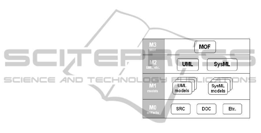
To this end, the MDA is centred on the Meta
Object Facility (MOF), a meta-meta modeling
language (a standard language to build meta-models)
at the top of a four layers hierarchy as depicted in
Figure 1. The next level (M2-models) includes the
UML or SysML meta-models, that is, models that
describe UML or SysML themselves. M2-models
describe elements of the M1-layer, which are, for
example, models of a specific system written in
SysML. Finally, the M0-layer or data layer is used to
describe real-world objects.
The MDA is model-driven because it provides a
means for using models to direct the course of
understanding, design, construction, deployment,
operation, maintenance and modification.
The most important means to manage models are
transformations, defined in (Mens, Czarnecki and
van Gorp, 2005) as “the automatic generation of a
target model from a source model, according to a
transformation definition ”, which is, in turn: “a set
of transformation rules that together describe how a
model in the source language can be transformed
into a model in the target language”.
In (Mens, Czarnecki and van Gorp, 2005) the
authors also provide a taxonomy for model
transformations according to which a transformation
can be:
Exogenous: when the source and target models
conform to the same meta-model;
Endogenous: when the source and target
models do not conform to the same meta-
model;
and
Vertical: when the source and target models
reside at different abstraction levels.
Horizontal: when the source and target models
reside at the same abstraction level.
The OMG provides standard languages for
model-to-model transformations, such as the Query
View Transformation (QVT) language, and model to
text transformations, such as the MOF to Text
transformation Language. A widely adopted CASE
tool enabling a model-driven workflow compliant to
the MDA standards is the Eclipse Modeling Project
(EMP) .
EMP provides an implementation of the MOF
language called Ecore. Ecore allows to define M2-
models from which editors for M1-models can be
generated. Then, models can be graphically defined
and saved in the standard XMI format.
Moreover, the EMP provides:
an Eclipse plugin implementing the QVT
language to define transformations between
models possibly conformant to different meta-
models (expressed in ECORE);
an Eclipse plugin (called Acceleo)
implementing the MOF to Text
Transformation Language which allows
engineers to define transformations from
models conform to a specified meta-model
(expressed in ECORE) and text.
The examples presented in this paper have been
realized using TopCased, an open source extension
of the Eclipse Modeling Project providing an
ECORE implementation of the SysML profile and
related editors.
Figure 1: Layers of the Model Driven Architecture.
4 SYSML AND SIMULINK
The Systems Modeling Language (SysML) (Hause,
2006) is a general-purpose modeling language for
systems engineering applications. It supports the
specification, analysis, design, verification and
validation of a broad range of systems and systems-
of-systems. It is defined as an extension of a subset
of the Unified Modeling Language (UML).
The major structural extension in SysML is the
«block» which extends the UML Structured Class
(Hause, 2006). It is a general purpose hierarchical
structuring mechanism that abstracts away much of
the software-specific detail implicit in UML.
Blocks can represent any level of the system
hierarchy including the top level system, a
subsystem, or logical or physical component of a
system or environment. Moreover, SysML blocks
can represents hardware, firmware or software
components, their parts, their interfaces and the data
(signals) transferred among them.
An OMG SysML block describes a system as a
collection of parts and connections between them
SIMULTECH 2011 - 1st International Conference on Simulation and Modeling Methodologies, Technologies and
Applications
48
that enable communication, data transfer and other
forms of interaction.
Ports provide interaction points for the
communication and synchronization among blocks,
when they are used within the context of a larger
structure. SysML provides Standard Ports, which
support client-server communication (e.g., required
and provided interfaces) and FlowPorts that define
flows in or out of a block (a signal or data interface).
Block Definition Diagrams (bdd) are used to
describe the blocks, with their port interface and
their internal attributes operations, parts and
constraints. Also, a bdd diagram defines the
relationships that exist between blocks. Internal
Block Diagrams (ibd) instead are used to provide a
description of the block internal structure, the type
of composition and the topology of internal
communications.
For the sake of simplicity, and also to show how
our approach can be applied to independently
realized SysML models, we propose the SysML
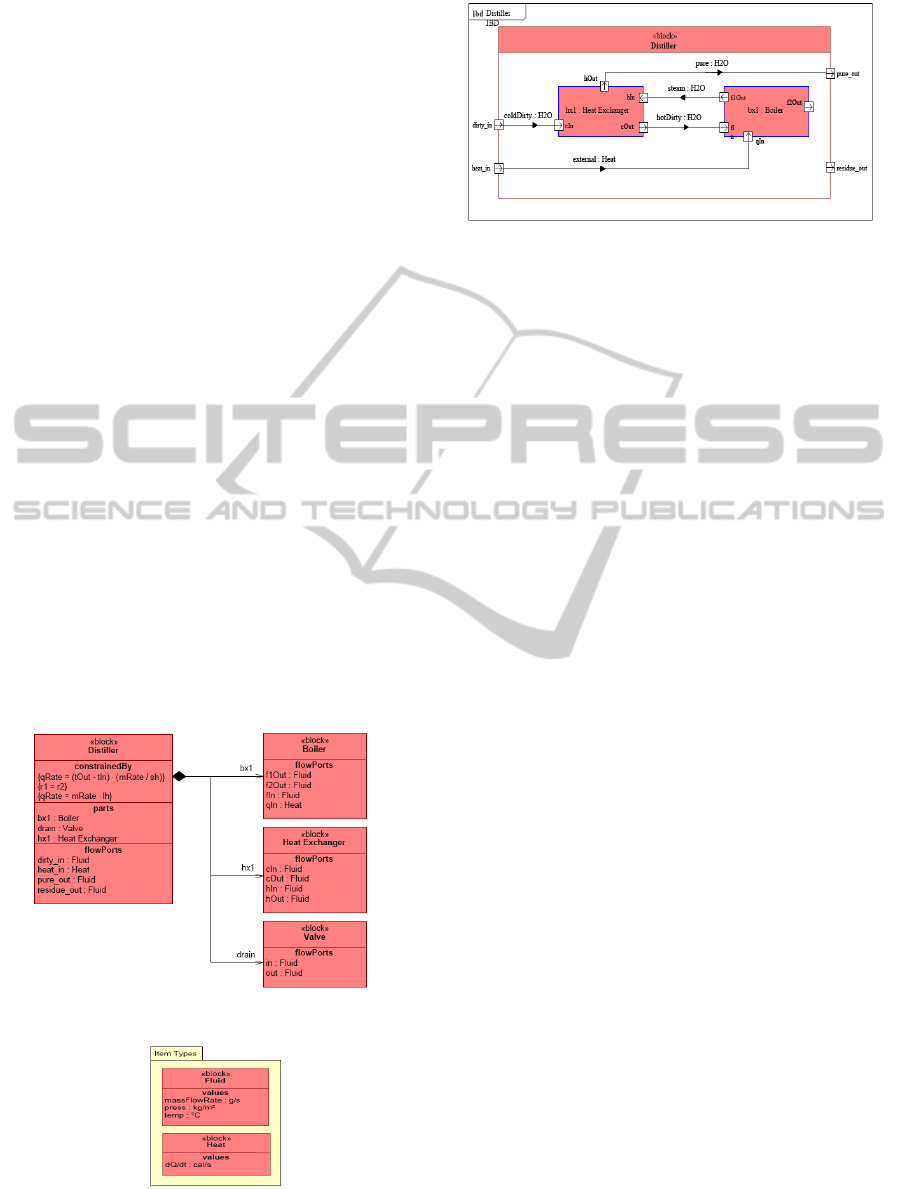
Distiller example described in (Hause, 2006).
The Distiller block definition diagram is depicted
in Figures 2,3. A distiller is represented as a block
composed of other blocks, including a Boiler, a Heat
Exchanger and a drain Valve.
A simple example of an internal block diagram
(ibd) is shown in Figure 4. It shows how the data
obtained as input by the distiller are processed and
communicated by its component parts to obtain the
output data on its output ports.
Figure 2: The Distiller Block Diagram.
Figure 3: Port Types specification.
Figure 4: The Distiller Internal Block Diagram.
Simulink, developed by MathWorks, is a
commercial tool for the modeling, simulation and
analysis of multidomain dynamic systems.
Simulink allows modeling and simulation of
dynamic systems according to a synchronous
reactive model of computation. A Simulink system
is a network of blocks. Each block (in essence a
Mealy machine) transforms an input function (of
time) into an output function. The input function’s
domain can be a set of discrete points in time
(discrete-time signal) or it can be a continuous time
interval (continuous-time signal). Continuous blocks
have a nominal sample time of zero, but in practice,
they are implemented by a solver, executing at the
base rate. Eventually, every block has a sample time,
which is an integer fraction of the base rate.
Simulink computes for each block, at each step, the
set of outputs, as a function of the current inputs and
the block state, and then, it updates the block state.
A cyclic dependency among blocks where output
values are instantaneously produced based on the
inputs results in a fixed point problem and possibly
inconsistency.
A fundamental part of the model semantics are
the rules dictating the evaluation order of the blocks.
Any block for which the output is directly dependent
on its input (i.e., any block with direct feedthrough)
cannot execute until the blocks driving its inputs
execute. Executing a block means computing the
output function, followed by the state update
function.
Of course, Simulink is supplement with a quite
large library of systems and blocks that can be
reused. In addition, simulink builds on top of the
Matlab environment which offers an additional
library of code implementations of mathematical,
logic control and signal processing functions.
For these reasons Simulink is nowadays widely
used in control theory and digital signal processing
for multidomain simulation and Model-Based
Design.
INTEGRATING SYSML WITH SIMULINK USING OPEN-SOURCE MODEL TRANSFORMATIONS
49
In Simulink, subsystems are a unit of
encapsulation of behavior and the minimum unit for
the code generation process. Simulink subsystems
communicate through data ports, connected by
signal links. Data ports and signals are typed by
primitive types as defined by the tool (integers,
reals, booleans) or composite types, defined by the
user as Bus Objects.
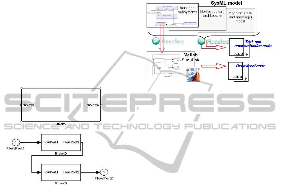
Figure 5-a depicts an example of a Simulink
subsystem, called BlockA, having both an input Port
(FlowPort1) and an output Port (FlowPort2). The
internal view of the subsystem, showing how the
data received from the input is processed by the
subsystem blocks to produce the output signals is
shown in Figure 5-b (in a way similar to a SysML
internal block diagram).
Figure 5: An example of Simulink model.
5 PROPOSED FRAMEWORK
Our proposed framework is summarized in Figure 6.
For simplicity, we describe it assuming a pure top-
down development, although this is not required,
since the framework supports also a bottom-up
approach. The system is initially developed and
partitioned in its major functional subsystems and
components as a SysML model. Similarly, SysML
supports the definition of the model of the execution
architecture.
The functional model includes the definition of
the main functional subsystems (or SysML blocks)
and their communication through ports. Subsystems
are decomposed until they get to the level of units of
deployment (that can be atomically allocated to
computation nodes). Some of the SysML functional
blocks can then be identified as executing according
to a SR semantics (by means of suitable
stereotypes). The execution architecture includes the
model of all HW nodes, including firmware targets
(FPGAs) and computing cores, of the networks and
other communication buses/links and of shared
memories.
Figure 6: A Transformation Workflow Integrating SysML
with Simulink.
Finally, a mapping layer completes the definition
of the Platform Specific Model. Its aim is setting up
an allocation relationships:
between functional subsystems and
computation cores
between communication flows and messages
between messages and networks in the case of
distributed communication,
between communication flows and shared
memory locations in the case of software to
firmware or intercore communications.
The behavior of some of the functional
subsystems may be critical for the functioning of the
system or their development may benefit for the use
of simulation and verification capabilities.
For these subsystems Simulink models will be
developed using model-to-model transformations to
retain the consistency of the subsystem interface
specification.
These Matlab/Simulink models can be executed
and therefore validated against the available test
cases (possibly automatically generated as well).
In the development of the internal behavior, it is
possible that the need to update the subsystem
interface arises, generating a design iteration with a
required change to the higher-level SysML model.
Code is generated from the models exploiting
their capabilities and their information content.
Behavioral code is generated from Matlab/Simulink
models using the Real-Time Workshop/Embedded
Matlab Coder suite, given that behavioral models are
produced and validated in this toolset. The code
implementing the tasks, as well as the
communication (intertask, intratask, but also remote)
code and part of the code implementing software-to-
SIMULTECH 2011 - 1st International Conference on Simulation and Modeling Methodologies, Technologies and
Applications
50

firmware communications, is generated from SysML
models, given that this is the place where knowledge
of the physical architecture and of the mapping of
the functional subsystems into tasks and computing
nodes is defined.
The code generation part of the project is still in
progress. In this work we are documenting the
model-to-model transformation technologies and the
templates we used.
6 A SYSML TO SIMULINK
MODEL TRANSFORMATION
Given that our objective is the transformation of a
SysML model into a Simulink model (and vice-
versa), the OMG QVT language seems to be a
suitable candidate.
However, QVT assumes that both the source and
target languages conform to meta-model
specifications expressed by MOF. Unfortunately,
while this holds for SysML, there is no available
MOF description of the Simulink language.
For this reason, QVT transformations are not
applicable and we must therefore use a model-to-text
transformation that translates a source SysML model
into a Matlab model generation script.
The output Matlab script can be processed by the
Matlab engine to obtain a Simulink model having
the same expressiveness of the source SysML
model.
In the opposite direction, a matlab script parses
the Simulink model and generates an XML model
description that can be transformed into XMI (the
standard input language for SysmML tools,
supported by Topcased)
The SysML-to-Matlab transformation has been
defined by means of the Acceleo template language:
an Eclipse implementation of the OMG MOF2Text
Transformation Language.
For lack of space we do not provide a description
of the Acceleo syntax and semantics which can be
found in the related OMG standard. However, we
provide a short description of the rationale behind
the transformation workflow together with a
complete transposition of the transformation script.
For the same reason, and for the sake of clarity
also, we do not provide the complete Acceleo code
of the transformation but only its workflow by
means of the involved acceleo template.
Omitted contents are however properly
commented to let the reader understand how the
transformation is performed.
According to the transformations taxonomy
defined in (Mens, Czarnecki and van Gorp, 2005),
our SysML to Simulink transformation can be
classified as endogenous, since the source and target
languages conform to different meta-models, and
horizontal, since both the source and target models
reside at the same level of abstractions (no further
details are added during the transformation.)
The following Table summarizes the mapping
applied in our transformation workflow from SysML
to Simulink.
The transformation starts from the root element
of the source model which is passed as parameter to
the generateModel template.
SysML Simulink Note
Block Block Each SysML block is
mapped to a Simulink
Block
Blocks
Composition
Subsystem
Blocks
SysML Blocks
consisting of a
number of other
Blocks (its parts) are
mapped to Simulink
Subsystem Block
FlowPort Input / Output
Blocks
SysML FlowPort are
mapped to Input and
Output Blocks
FlowSpecification Bus Object SysML Flow
Specification used to
type FlowPort is
mapped to a Simulink
Bus Objects
Connector Line Each SysML
connector is mapped
to a Simulink line
connecting to ports.
These ports can be
typed with Bus
Objects specifying the
type of data that will
be transferred
through the line
The transformation starts from the root element
of the source model which is passed as parameter to
the generateModel template.
This template creates a Simulink Bus Object for
each FlowSpecification associated with a FlowPort
of the SysML source model.
Then, the workflow continues by invoking the
template generateRootBlock, aimed at generating
the SimuLink representation of the SysML root
Block in the model.
[template public generateModel(p : Model)]
[comment @main /]
INTEGRATING SYSML WITH SIMULINK USING OPEN-SOURCE MODEL TRANSFORMATIONS
51

[file (p.name.concat('.m'), false, 'UTF-8')]
sys = '[p.name/]';
new_system(sys) % Create the model
open_system(sys) % Open the model
load_system('eml_lib');
[comment Matlab code initializing the
environment/]
[let classifiers:Set(Element)
= p.allOwnedElements()]
[for (cl:Classifier |classifiers)]
[if cl.isFlowSpecification()]
busCell = { ... '[cl.name/]','Header
[comment a bus cell is created for each Flow
Specification in the source SysML model /]
}; ...};
Simulink.Bus.cellToObject(busCell);
[/if][if isBlock(cl)]
[if owners(cl)->isEmpty()]
[generateRootBlock(cl)/]
[/if] [/if] [/for] [/let]
[/file]
[/template]
[template public generateRootBlock(cl :
Classifier)]
[if owned(cl)->isEmpty()]
[else]
[cl.name/]X=0; [cl.name/]Y=0;
add_block('built-in/Subsystem',['['/]sys
'/[cl.name/]' [']'/]);
[generatePort(cl,'/'.concat(cl.name))/]
[for (a:Association | owned(cl))]
[comment X and Y contains the position
assigned to the Simulink block in the
generated model /]
[cl.name/]X=[cl.name/]X+1;
[cl.name/]Y=1+floor([cl.name/]X/blockStep);
[generatePart(
a.memberEnd->at(2).type,'/'.concat(cl.name),
cl.name.concat('X'),cl.name.concat('Y'))/]
[/for]
[generateConnector(cl,'/'.concat(cl.name))/]
[/if]
[/template]
The template generateRootBlock also triggers
the generation of the root block ports (the
generatePort template invocation), the parts
composing the root block through the invokation of
the
generatePart template.
This template adds a new Simulink Subsystem
Block to the block passed as parameter. It also has
the responsibility of generating its ports
(
generatePort template) its parts (by the recursive
invocation of the
generatePart template) and its
connectors (
generateConnector).
[template public generatePart(b:Type,
p:String, x:String, y:String)]
[let c:Classifier = b]
[b.name/]X=0;[b.name/]Y=0;
[if isBlock(c)]
[if owned(c)->isEmpty()]
add_block('built-in/Subsystem',
['['/]sys
'[p.concat('/').concat(b.name)/]'
[']'/],'Position',['['/][x/]*offset
[y/]*offset/2 [x/]*offset+100
[y/]*offset/2+50 [']'/]);
[generatePort(c,p.concat('/').
concat(c.name))/]
[else]
add_block('built-in/Subsystem',['['/]sys
'[p.concat('/').concat(b.name)/]'
[']'/],'Position',['['/][x/]*offset
[
y/]*offset/2 [x/]*offset+100
[y/]*offset/2+50 [']'/]);
[generatePort(c,p.concat('/').
concat(c.name))/]
[for (a:Association | owned(c))]
[b.name/]X=[b.name/]X+1;
[b.name/]Y=1+floor([b.name/]X
/blockStep);
[generatePart(a.memberEnd
->at(2).type,p.concat('/').
concat(c.name),b.name.concat('X'),
b.name.concat('Y'))/]
[/for][/if][/if]
[generateConnector(c,p.concat('/').
concat(c.name))/]
[/let]
[/template]
[template public generatePort(b:Block,
name:String)]
[for (port:FlowPort |b.ownedPort)]
[let fd:FlowDirection = port.direction]
[if fd.toString()='in']
add_block('built-in/Inport',['['/]sys
'[name/]/[port.name/]'
[']'/],'MakeNameUnique','on','Position',
['['/]0 150 20 170[']'/]);
[/if]
[if fd.toString()='out']
add_block('built-in/Outport',['['/]sys
'[name/]/[port.name/]'
[']'/],'MakeNameUnique','on','Position',
['['/]600 150 620 170[']'/]);[/if]
portId{end+1} = get_param(strcat(sys,
portVocabulary{end}),'Port');
[/let]
[if port.type.
oclIsKindOf(FlowSpecification)]
set_param(strcat(
sys,'[name/]/[port.name/]')
SIMULTECH 2011 - 1st International Conference on Simulation and Modeling Methodologies, Technologies and
Applications
52
,'UseBusObject','on');
set_param(strcat(
sys,'[name/]/[port.name/]')
,'BusObject','[port.type.name/]');
[/if] [/for]
[for (c:ConnectorProperty |
b.ownedConnector)] [/for]
[/template]
The generatePort template adds the specific
blocks representing SimuLink in and out ports
accordingly to the SysML source model FlowPort
which has been passed as parameter.
Moreover, when the FlowPort is typed by a
FlowSpecification it generates the Matlab code that
assigns it to the related Bus object, generated at the
beginning of the transformation flow.
[template public
generateConnector(b:Classifier,p:String)]
node = strcat(sys,'[p/]');
[for (c:Connector|b.ownedElement)]
[comment stating whether the outputport
belong or not to the currently managed block
and, depending on this, retrieving its
handler/]
[if c.end->at(1).partWithPort->isEmpty()]
[comment ..code to get the port handler/]
[else]
[comment ..code to get the port handler/]
[/if]
[if c.end->at(2).partWithPort->isEmpty()]
[comment ..code to get the port handler/]
[else]
[comment ..code to get the port handler/]
[/if]
[comment adding the simulink line between
the two identified ports/]
try
add_line(node,outPort,inPort);
catch exception
add_line(node,inPort,outPort);
end
[/for]
[/template]
7 A TRANSFORMATION
EXAMPLE
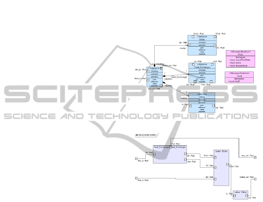
We have selected the SysML model of a Distiller
proposed in (Hause, 2006) and depicted in Figures 2,
3 and 4 as an example for the application of our
transformation scripts. We defined the Distiller
model in TopCased by means of a SysML
BlockDiagram and Internal Block Diagram (Figures
7 and 8). The only change to the original model is
that FlowPorts are typed with FlowSpecifications
instead of Blocks. This has been made to make the
model more formal and unambiguous and facilitate
parsing and interpretation. We have applied the
transformation workflow described in section IV to
our Distiller SyML source model and obtained a
Matlab script that generates a Simulink model
conform to the source SysML model.
Figure 7: A TopCased Block Diagram for the Distiller.
Figure 8: The Distiller Internal Block Diagram.
For lack of space we do not show the resulting
Matlab script (which can be derived from the
Acceleo code and does not provide any additional
information.).
When executed in the Matlab environment, the
Simulink model is automatically created as shown in
Figure 9.
The Distiller Simulink block is correctly created
with its two input ports and two output ports.
When the user double clicks on it, very similarly
to what happens in Topcased for the same SysML
model, another view opens (Figure 9) representing
the internal model of the block.
The Simulink internal block representation is
very similar to the source SysML model (its internal
block diagram) from which it has been generated.
INTEGRATING SYSML WITH SIMULINK USING OPEN-SOURCE MODEL TRANSFORMATIONS
53
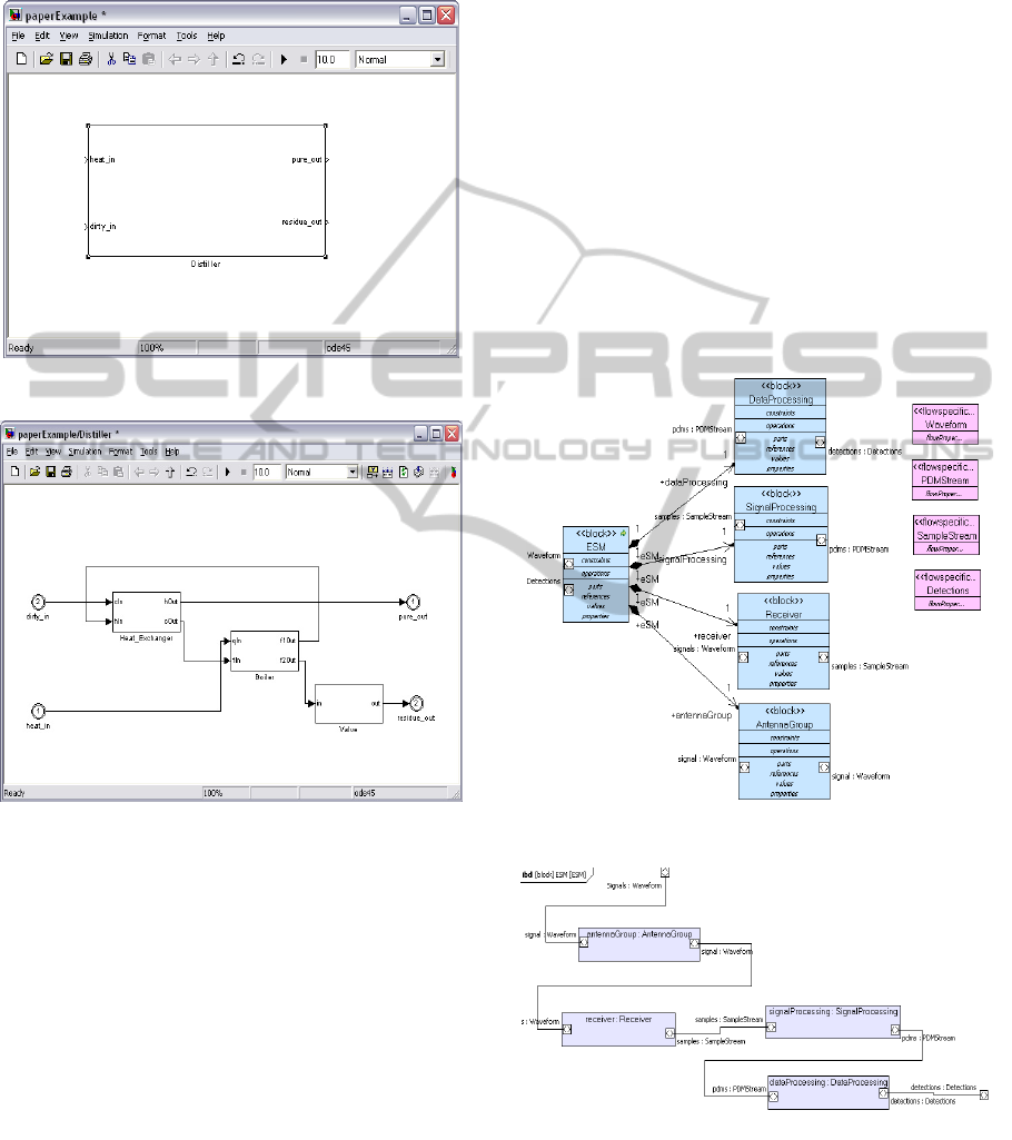
Each part is represented by a subsystem and
subsystem ports are assigned a BusObject type
according to the related SysML FlowSpecifications
and connected as in the SysML model.
Figure 9: The Simulink Distiller Model.
Figure 10: The Simulink Distiller Internal Model.
8 A MODEL DRIVEN
ENGINEERING EXAMPLE OF
ELECTRONIC DEFENCE
SYSTEM
The presented workflow has been designed and
realized as part of a Model Driven Development
process that Elettronica S.p.A has adopted for
designing its products. With the aim of providing a
very high level demonstration of how this process
can be applied to the design of complex systems in
this section we provide a further example related to
Electronic Warfare (Vakin, 2001), the Elettronica
S.p.A. core business, and particularly to the design
of an ESM system (ESM), a passive sensor capable
of detecting radars emissions. An ESM system could
be, simplicistically, modeled as being composed by
the following macro components:
A group of antennas: aimed at receiving radars
signals which are possibly present in the
surrounding electromagnetic environment;
A receiver: capable of transforming analogic
signals retrieved from the connected antennas
into a stream of digital samples;
A signal processing component: aimed at
synthesizing from group of samples belonging
to the same electromagnetic pulse a synthetic
digital representation of each pulses called
Pulse Descriptor Message (PSM);
A data processing component: aimed at synthesizing
from a group of PSMs emitted by the same Radar a
synthetic representation of the Radar characteristics.
Figure 11: A SysML Block Diagram for an ESM System.
Figure 12: A SysML Internal Block Diagram for an ESM
System.
We designed the ESM Block as consisting of the
following parts:
SIMULTECH 2011 - 1st International Conference on Simulation and Modeling Methodologies, Technologies and
Applications
54
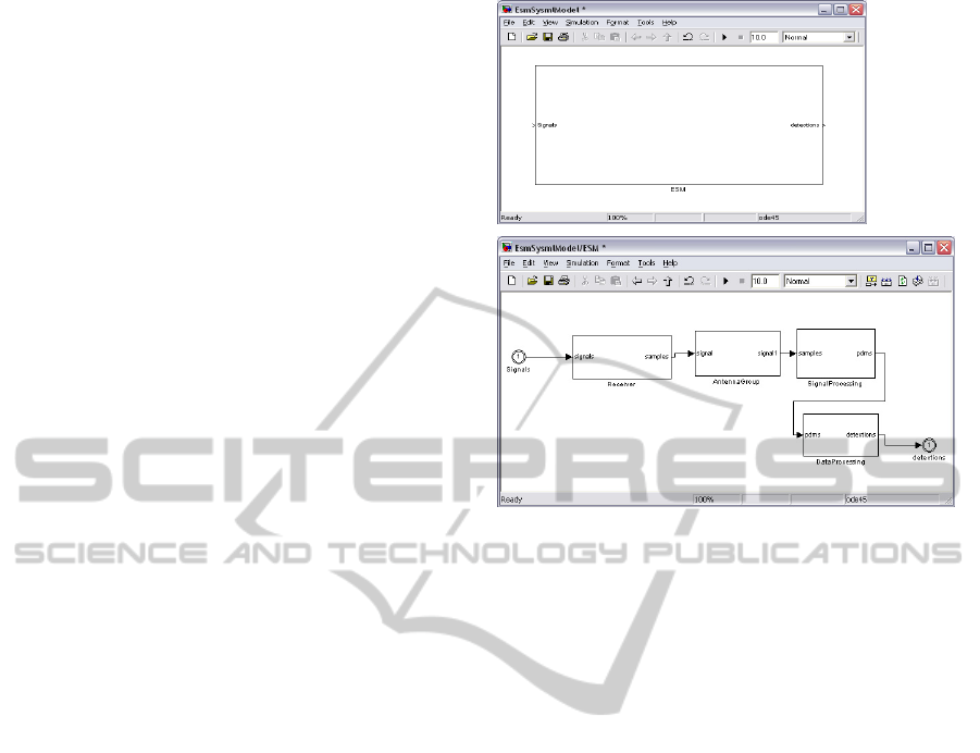
an AntennaGroup Block, representing the ESM
group of antennas. This block provides two
ports:
o an input port representing signals
illuminating the antennas
o an output port representing the subset of
signals intercepted by the antennas
A Receiver Block, representing the ESM
receiver. It provides two ports:
o An input port representing signals
retrieved from the AntennaGroup Block;
o An output port representing samples
produced by the Receiver Block
A Signal Processing Block representing the
related ESM signal processing component.
It provides two ports:
o An input port representing samples
retrieved from the Receiver Block
o An output port representing the stream of
PSMs synthesized by the Signal
Processing Block
A Data Processing Block representing the
related ESM Data Processing component.
It provides two ports:
o An input port representing PSMs
retrieved from the Signal Processing
Block
o An outpot port representing synthetic
detections created by the Data Processing
Component
Figure 12 depicts the Internal Block Diagram of the
ESM Block. This kind of representation is useful for
System Engineers in order to design the system
starting from its high level representation and then
going deep within the inner architecture of its parts
and sub components. Each of these parts can be
further decomposed into sub-parts and more detailed
by means of additional Internal Block Diagrams.
Once these models are completed, System Engineers
pass them along to HW, FW and SW Engineers
involved with the realization of each system
component. At this stage, Simulink models can be
generated matching the original source SysML
specification. HW, FW, and SW Engineers can
proceed by working on the executable Simulink
models performing simulation, test generation, test
coverage analysis and code generation.
9 CONCLUSIONS & FUTURE
WORKS
In this paper we have briefly described an automatic
Figure 13: The generated Simulink Model automatically
obtained from the related SysML source model.
model transformation aimed at obtaining Simulink
models conform to SysML source models. This
result represents just a first step in the definition of a
unified modeling framework in which OMG
languages (i.e. UML, SysML, etc.), particularly
suitable to capture architectural aspects, are
seamlessly integrated with Mathworks technologies
(i.e. Matlab, Simulink, etc.) very adapt for the
definition of executable models of signal and data
processing. Although the process we have defined
has been implemented by means of OMG standards
it is still slightly informal since the most formal way
to transform SysML into Simulink should be a
model to model, and not a model to text,
transformation based on both the SysML and the
Simulink meta-models. To this end in the future
works we are going to provide ECORE defined
meta-models for a subset of the Simulink languages
enabling this kind of transformation too. Our process
also lacks of a transformation from Simulink to
SysML that could be useful when Simulink models
are already available and a SysML model is desired.
We are already working on this kind of
transformation that is basically based on matlab
scripts capable of producing XMI description of
SysML models conform to source Simulink models
available in the Matlab workspace.
INTEGRATING SYSML WITH SIMULINK USING OPEN-SOURCE MODEL TRANSFORMATIONS
55

REFERENCES
Acceleo: http://www.acceleo.org/pages/accueil/fr
AUTOSAR. 2010. Autosar release 4.0 specifications.
available at http://www.autosar.org/.
Balarin, F., Lavagno, L., Passerone, C., and Watanabe,
Y.,2002, Processes, interfaces and platforms.
Embedded software modeling in Metropolis. In Proc.
of the 2nd ACM EMSOFT, Grenoble, France, Oct.
Benveniste, A., Caspi, P., Edwards, S.A., Halbwachs, Le
Guernic, N., P., and de Simone, R..,2003, The
synchronous languages 12 years later. Proceedings of
the IEEE, ISSN 0018-9219
Deutsche Bank F.I.T.T., 2005, EDA Survey Results
Electronics Weekly & Celoxica, 2005, Survey of System
Design Trends 2005, http://www.celoxica.com
Electronic Support Measures: http://en.wikipedia.org/
wiki/Electronic_warfare_support_measures
ESL Now Survey, 2005, http://www.esl-now.com
Elettronica S.p.A.: http://www.elt-roma.com
EMP: The Eclipse Modeling Project: http://
www.eclipse.org/modeling/
Hause, M., 2006, The sysML Modeling Language, Fifth
European Systems Engineering Conference
Karsai G., Maroti M., Ledeczi A., Gray J., Sztipanovits
J.2003, Composition and Cloning in Modeling and
Meta-Modeling, IEEE Transactions on Control System
Technology
Kawahara, R., Nakamura, H., Dotan, D., et al, 2009,
Verification of embedded system's specification using
collaborative simulation of SysML and Simulink
models. International Conference on ModelBased
Systems Engineering, MBSE 2009, 2009.
Kienhuis, B., Deprettere, E. F., van der Wolf, P., and
Vissers, K. A. 2002, A methodology to design
programmable embedded systems - the Y-chart
approach, In Embedded Processor Design Challenges:
Systems, Architectures, Modeling, and Simulation –
SAMOS. Eds. Lecture Notes in Computer Science,
vol. 2268. Springer, 18–37.
Martınez, J., Merino, P., Salmeron, A., 2007, Applying
MDE Methodologies to Design Communication
Protocols for Distributed Systems, Proceedings of the
First International Conference on Complex, Intelligent
and Software Intensive Systems
MathWorks: http://www.mathworks.com
Matlab: http://www.mathworks.com/products/matlab/
Mens, T., Czarnecki, K., Van Gorp, P., 2005, A Taxonomy
of Model Transformation, Electronic Notes in
Theoretical Computer Science, 152 (1-2), pp. 125-142
MDA: Model Driven Architecture: http://www.omg.org/
mda/
MOF: MetaObject Facility http://www.omg.org/mof/
MOF Model To Text Transformation Language:
http://www.omg.org/spec/MOFM2T/1.0/
Nicolescu, G., Mosterman, P. J., 2009, Model Based
Design for Embedded Systems (Computational
Analysis, Synthesis and Design of Dynamic Systems),
CRC Press, ISBN-10: 1420067842, November 24
OMG: Object Management Group http://www.omg.org/
QVT: Query/View/Transformation Language http://
www.omg.org/spec/QVT/1.0/
Sangiovanni-Vincentelli, 2007, A., Quo Vadis, SLD?
Reasoning About the Trends and Challenges of System
Level Design, Proceedings of the IEEE, vol. 95, n. 3,
pp. 467–506
Schmidt, D.C., 2006, Model Driven Engineering, IEEE
Computer V.39 n.2, p.25, February 2006
Soley, R., 2000, Model-Driven Architecture
SysML: Systems Modeling Language http://
www.omgsysml.org/
Symulink: http://www.mathworks.com/products/simulink/
UML: Unified Modeling Language http://www.uml.org/
TopCased: http://www.topcased.org
Vanderperren, Y., Dehaene, W., 2006, From UML/SysML
to Matlab/Simulink: Current State and Future
Perspective, In the Proceedings of the conference on
Design, automation and test in Europe
Vakin, S. A., Shustov, L. N., Dunwell¸R. H., 2001,
Fundamentals of Electronic Warfare, Artech Hous
Radar Library
SIMULTECH 2011 - 1st International Conference on Simulation and Modeling Methodologies, Technologies and
Applications
56
