
HUMAN BODY AS A MECHATRONIC SYSTEM
Complex Modelling, Simulation and Control
Dorin Andreescu
1
, Hartmut Riehle
2
, Florin Ionescu
3,4
and Stefan Arghir
5
1
W
¨
urttembergischer Leichtathletik-Verband e.V., Stuttgart, Germany
2
University of Konstanz, Konstanz, D-78467, Germany
3
University of Applied Sciences HTWG Konstanz, D-78462, Konstanz, Germany
4
Steinbeis Transfer Institute Dynamic Systems, D-10247, Berlin, Germany
5
University ”Politehnica” of Bucharest, RO-060042, Bucharest, Romania
Keywords:
Human body, Multibody mechanics, 3D CAD, 3D CAE, Identification, Modelling, Simulation.
Abstract:
The modelling of the human locomotor system and its simulation are subjects of intensive studies, due mostly
to the development of the computer processing power and the appropriate software. Most fields of application
are located in the reconstruction of human movements: the motor, its transmission and the necessary control
systems. The goal to have a general approach fully describing the Human Body as a System, with high
accuracy and open set of functions for its entire complexity is still to be reached. Envisioning the body as
an open system we refer to: the 3D-geometry of all bones and their 3D-defined positions (six degrees of
freedom, the corresponding coordinates, restrictions and anomalies), the joints, ligaments and muscles with
their frictions, both viscous and dry, and the contact pressures, the sensorial system with its information
conduits and control mechanism and, last but not least, the human brain, as a hard-soft-controller for this
most intricate and complex system that is the human body. This paper presents some main ideas for this
approach and achieved results concerning steps on the way towards obtaining this goal. The first beneficiaries
to welcome these results are, on the one hand, the sportsmen and, on the other, the architects and engineers
working on humanoid robots.
1 INTRODUCTION
The goal of this paper is to demonstrate a practical
approach towards 3D modelling and simulation of a
realistic human body. More specifically, it focuses, as
a first step, on how to gain the most valuable informa-
tion about a real athlete.
Practically, the paper is focusing on the modelling
of the body and the locomotor system as an inverse
dynamic paradigm. While any human mechanical
system can be moved with direct and inverse dynam-
ics, we have selected the second approach, as conve-
nient for research stage (Andreescu et al., 2007). Thus
one can consider, that any human body can be de-
scribed as a specifically adapted abstraction as a gen-
erally defined solid multibody system. It follows the
CAD-methodology typical for machine or plant de-
sign. This approach will be illustrated, step by step,
in the following chapters and accompanied by appro-
priate figures.
The body receives information through various
sensors distributed all over the body. This includes:
hearing (both frequency and amplitude are qualita-
tively ”understood”), seeing (concerning images as
forms, colours, distances, movements) tasting, touch-
ing (concerning pressure, temperature and humidity),
smell. Information from outside the body is received
by the different sensorial organs via different types
of energy corresponding to each of the five human
senses. Data from the sensors are then directed to
the brain directly or indirectly through various relay
stations in the form of bio current.
In Figure 1 the sensors are noted with s
k
, while
e
l
denotes, in a simplified manner, some well known
hand and foot joints. The brain receives and processes
all the signals in order to produce an effect on the en-
vironment.
To obtain a Model of the Human Body to be sim-
ulated, two paradigms of thinking are used, by adopt-
ing the manner of robot modelling (Stefanoiu et al.,
2004; Borangiu and Ionescu, 2002):
339
Andreescu D., Riehle H., Ionescu F. and Arghir S..
HUMAN BODY AS A MECHATRONIC SYSTEM - Complex Modelling, Simulation and Control.
DOI: 10.5220/0003600903390342
In Proceedings of 1st International Conference on Simulation and Modeling Methodologies, Technologies and Applications (SIMULTECH-2011), pages
339-342
ISBN: 978-989-8425-78-2
Copyright
c
2011 SCITEPRESS (Science and Technology Publications, Lda.)
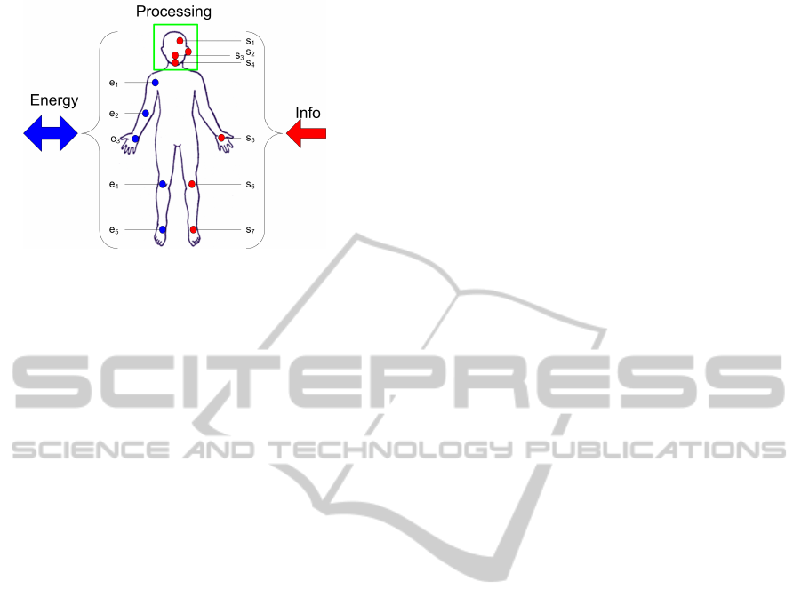
Figure 1: The human body as an open system.
1. The Direct Dynamics (DD), which corresponds to
the previously described mode: starting from the
brain a set of commands are provided via nerves
to the muscles giving them the order to act; the
body is moving according to the set of commands,
by consuming energy. During the movement the
brain is continuously correcting the command set,
in order to attain the desired input variables set;
2. The Inverse Dynamics (ID) implies a different
way for the flow of information and it only exists
in theory: the realistically achievable movement
of different reference points (joints, for example)
is given, from what the forces and moments of all
joints. Thus, all the human body parts are moved
as a result of the energies calculated to be needed
to be introduced into the body via the imposed
movements.
The ID paradigm was used for the present re-
search. The model to be simulated is a reconstruc-
tion/replica of a real skeleton. Having chosen a spe-
cific skeleton, a real human being must be found hav-
ing very close constitutional resemblance. On this
real human being it can measured, by using appro-
priate techniques, the movement of the appropriately
selected joints/points. Afterwards, data have to be
denoised and organised as ASCII files. Through the
ASCII file, these points can be assigned to the corre-
sponding points on the Computer Model.
2 MATHEMATICAL
FORMULATION
These interactions can be formulated as differential
equations of different types: mechanical, hydraulic,
electrochemical, and other. In the general form, such
a mechanical equation can be depicted as in 1. With
several such equations, a system is formed. Reference
for mathematical modelling of the human body can be
found in (Hanavan, 1964; Ballreich, 1996)
[M] · { ¨q
i
} + [D] · { ˙q
i
} + [C] · {q
i
} =
[A] · {
˙
Q
i
} + [B] · {Q
i
} + [E] · {U
i
} (1)
with: i ∈ [1, ..., 6n], k ∈ [6n − 5, ..., 6n], [M]-inertia
matrix {kg or Nms
−2
}; n - total number of de-
grees of freedom (DOF), [D]- the Damping Matrix
{in N/(m/s) or Nm/(rad/s)}; [C] - elasticity matrix
{N/m or Nm/rad}, [A] -coefficients’ matrix of the
first derivative of the perturbation vector {Q}; [B]-
coefficients’ matrix of the perturbation vector; [E]-
coefficients’ matrix of the input vector {U}.
3 FROM HUMAN SUBJECT TO
MODEL SKELETON
In order to model an simulate the human locomo-
tor system the authors applied a two step approach
(Riehle, 1979; Vieten, 2004; Zahran et al., 2002).
First the bones need to be mechanically modelled. For
this purpose a human skeleton was used. Each bone
is modelled independently.
After having the bones as separate static models,
they can be combined with joints to form a piecewise
modelled skeleton. Nevertheless, this is still a static
model. At this point we have obtained just an innert
object with no laws to move it or restrictions for the
movement.
The animation of the model will be done by mim-
icking the movements of a real human body. For this
purpose, a human test subject is needed. This per-
son must be healthy, at least without any locomotor
problems or peculiarities and he or she must have ap-
proximately the same dimensions as the skeleton used
previously to obtain the static model. More details on
the actual modelling are provided in Chapter 5.
4 DIRECT AND INVERSE
DYNAMICS
The direct dynamic problem consists of finding a
transformation matrix that relates the reference coor-
dinate frame to the reference frame of each segment
in a kinematic chain. In other words, the direct dy-
namic model determines the actual motion of a body
when certain forces and or moments of force are ap-
plied to certain points. Typically, it uses link-segment
models to represent the mechanical behaviour of in-
terconnected segments, such as the limbs of humans,
SIMULTECH 2011 - 1st International Conference on Simulation and Modeling Methodologies, Technologies and
Applications
340
animals or robots. Thus, the movement is completely
defined by the aggregated movements of all degrees
of freedom. Presuming that each articulation has a
maximum of 6 degrees of freedom, then the set of
equations described in 2 completely describes the cin-
ematic chain.
{ ¨q
k
} = −[D] · [M]
−1
· { ˙q
i
} − [C] · [M]
−1
· {q
i
}+
+[A] · [M]
−1
· {
¨
Q
i
} + [B] · [M]
−1
· {Q
i
}+
+[E] · [M]
−1
· {U
i
}
(2)
Inverse rigid-body dynamics is a method for comput-
ing forces and/or moments of force (torques) based
on the kinematics of a body and its inertial properties
(mass and moment of inertia). Opposite to the direct
dynamics, given the kinematics of the various parts,
the inverse dynamics derives the minimum forces and
moments responsible for the individual movements.
In practice, inverse dynamics computes these internal
moments and forces from measurements of the mo-
tion of limbs and external forces such as ground reac-
tion forces, under a special set of assumptions.
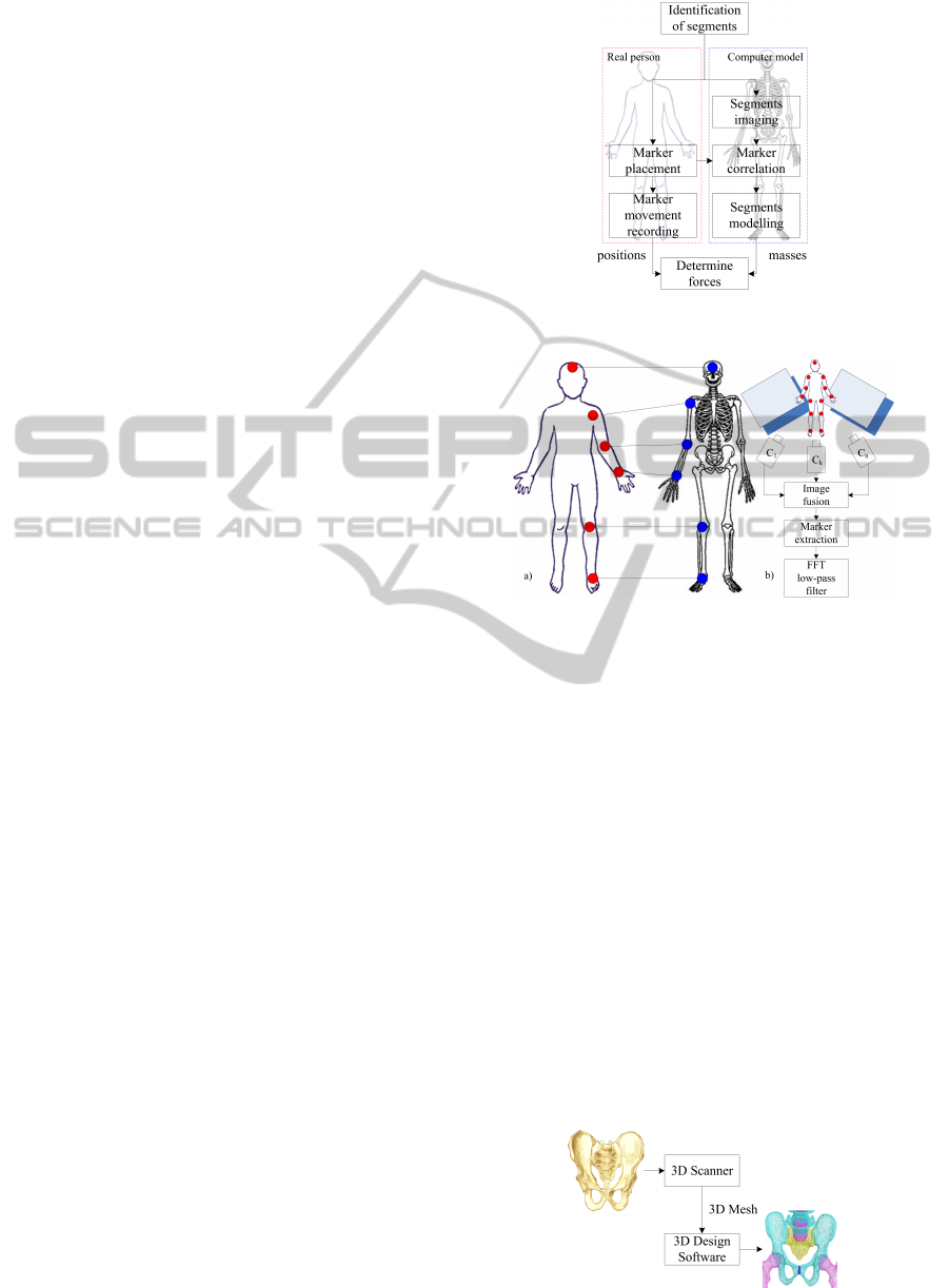
A general procedure is given in Figure 2.
The first step was to identify a suitable structure.
All bones of the human locomotor system were
identified. Each bone was described in terms of
weight, density and dimensions. All bones are con-
sidered to be perfectly rigid.
All joints were determined. The normal orienta-
tion for the coordinate frame was established for each
joint. The second step was to identify measurement
points on the skeleton model as shown symbolically
in Figure 3a
5 MODELLING
The modelling and simulation environment of choice
was Solid Dynamics SDS (SolidDynamics, 2005).
This software can only ”animate” solid bodies by ap-
plying predefined forces/torques. Paradigmatically,
this corresponds to the direct dynamics mode. As a
result, our case is basically an inverse dynamics prob-
lem: from the recorded movement of a real person,
the necessary forces are to be determined in order to
move each joint. This is shown in Figure 3b.
After selecting the segments of interest, several
markers were placed on the on the body of the ath-
lete.
Recording point movement was accomplished us-
ing procedure described in Figure 3b.
Modelling was done using mirrors in order to gain
more visibility on the markers. In case that during a
movement a certain marker gets hidden from a certain
Figure 2: Solving the inverse dynamic problem.
Figure 3: a) Identifying markers between real body and
model; b) Solving the inverse dynamic problem.
camera, then maybe that marker can be viewed in-
directly in one of the mirrors, thus insuring constant
marker tracking. Afterwards, during image process-
ing, virtual images in the mirror must be transformed
relative to the basis coordinate frame.
On the ASCI file, a FFT low pass filter was applied
in order to remove all the noise from the data. From
this processing, the path of each marker relative to
time is determined.
At this point, in order to calculate the forces driv-
ing the bodyes, all relevant masses are needed. To
this end, and considering a mean bone density, only
the volume of the bones must be determined. The
volume for each bone can be easily extracted from its
3D shape.
A 3D model of the bones is obtained by following
the procedure described in Figure 4.
Figure 4: Obtaining a 3D model of a bone.
HUMAN BODY AS A MECHATRONIC SYSTEM - Complex Modelling, Simulation and Control
341

Incidently, the scanning process provides noisy
outputs. Nevertheless, after some final manual modi-
fications, each bone from the locomotor system has a
3D model.
By having a 3D model of all the objects, based on
their dimensions and an average bone density, a mass
can be attributed to each one.
As a result, the force applied to each marker can
be easily determined from the formula F(t) = m·a(t).
6 SIMULATION
By applying this method, various techniques from dif-
ferent sports and other physical activities have been
modelled. Two examples are shown in Figures 5 and
6.
Figure 5: Athlete sprinting. 3 consecutive frames.
Figure 6: Piano playing. 3 consecutive frames.
7 CONCLUSIONS
The aim of the work was to illustrate a methodology
of representing the human body as a mechatronic sys-
tem. The modelling was performed in the multibody
technology and the preferred tool was the SolidDy-
namics Modelling and Simulation program.
Obtaining the models and animating them exceeds
the normal frame offered by SDS and its environment.
Thus, other means had to be employed.
An own technology was developed and presented
for obtaining models of the human body via scanning
of bones and their translation into generalised meshes
to be afterwards endowed with structural and dynam-
ical properties.
Different layers of pre processing software were
developed and are briefly presented in the paper. The
paper demonstrates that the implementation of mod-
ern technologies allows the modelling and simulation
of the human body as a most complex bio mechan-
ical system. New approaches and new generations
of computers will facilitate more and more complex
approaches, as already mentioned, as well as shorter
computing times, (quasi) real time simulations, the
gradual implementation of FEM components and a
bio control strategies for both direct and inverse dy-
namics.
Possible applications include medical care, post
traumatic or post accidental recovering, rehabilitation
of handicapped persons. In conjunction with the CAE
of medical and fitness machines as well as for sport ar-
ticles as shoes,and others, important information can
be obtained for an optimised design of these products
through simulation. The achieved results and the aux-
iliary methods used are quite promising. This opens
new prospects for further developments in various in-
dustrial applications.
ACKNOWLEDGEMENTS
The authors would like to express their gratitude for
the support to the University of Konstanz/Institute
of Sport Sciences, Deutsche Forschung Gemeinschaft
(DFG), Steinbeis Transfer Institute Dynamic Systems
of the Steinbeis University Berlin, and HTWG Kon-
stanz Germany.
REFERENCES
Andreescu, D., Ionescu, F., and Riehle, H. (2007). Mod-
elling and simulation of human body by considering
of skeletons bones. In Proceedings of IASTED Inter-
national Conference on Bio Mechanics, pages 153–
159, Hawaii, USA. ACTA Press.
Ballreich, R. (1996). Grundlagen der modellmethode. In
Grundlagen der Biomechanik des Sports: Probleme
Methoden, Modelle, pages 118–159. Ferdinand Enke
Verlag Stuttgart, Stuttgart.
Borangiu, T. and Ionescu, F. (2002). Robot Modelling and
Simulation. Academic Edition, Bucharest, Romania.
Hanavan, E. P. (1964). A mathematical model of the human
body. In AMRL TR, pages 64–102, Ohio, USA.
Riehle, H. (1979). Die biomechanik der wirbels
¨
aule
beim trampolinturnen. In Schriften der Deutschen
Sporthochschule K
¨
oln, volume 2. Richard Verlag.
SolidDynamics (2005). User Manual. Annecy, France.
Stefanoiu, D., Borangiu, T., and Ionescu, F. (2004). Robot
Modelling and Simulation-Problems and Solutions.
Academic Edition, Bucharest, Romania.
Vieten, M. (2004). Virtual Biomechanics and its Physics.
PhD thesis, Universit
¨
at Konstanz. Habilitation Thesis.
Zahran, K., Vieten, M., and Riehle, H. (2002). Quantifica-
tion of technical skills in weightlifting. In Gianikellis,
editor, XXth International. Symposium on Biomechan-
ics in Sport, page 478.
SIMULTECH 2011 - 1st International Conference on Simulation and Modeling Methodologies, Technologies and
Applications
342
