
COOPERATION OF CPU AND GPU PROGRAMS
FOR REAL-TIME 3D MAP BUILDING
Yonghyun Jo
1
, Hanyoung Jang
1
, Yeonho Kim
2
, Joon-Kee Cho
2
, Hyoung- Ki Lee
2
, Young Ik Eom
3
and JungHyun Han
1
1
College of Information and Communication, Korea University, Seoul, Republic of Korea
2
Samsung Electronics Co., Samsung Advanced Institute of Technology, Suwon, Republic of Korea
3
School of Information and Communications Engineering, Sungkyunkwan University, Suwon, Republic of Korea
Keywords:
GPU program, Map building, CUDA.
Abstract:
This paper presents how the CPU and GPU programs coordinate in the context of 3D map modeling for a
mobile home service robot. In this study, the representation of the environment is given as point clouds,
and each scan of point clouds is quite efficiently processed using the parallel processing capability of GPU.
Then, the result is read back to CPU for incrementally constructing the map. Due to the coordination between
the CPU and GPU, a 3D map can be built at real time. This paper presents the software architecture of the
CPU-GPU coordination, the GPU algorithm, and its performance gain.
1 INTRODUCTION
Recently, much attention has been directed to home
service robots such as cleaning robots while the mar-
kets for conventional industrial robots are saturating.
A home service robot requires a map, which is a spa-
tial model of the physical environment. In our study,
the environment is first captured as point clouds, and
then a 3D map is incrementally constructed from the
successive inputs of the point clouds. Noting that a lot
of planar surfaces, such as walls and floors, exist in
a typical indoor environments, we propose to extract
the plane information and store it into the 3D map.
CPU
GPU
scanning
map building
point clouds
(in a texture)
micro-planes
mean filtering
micro-plane
extraction
Figure 1: CPU-GPU coordination.
The algorithm proposed in this paper utilizes both
the CPU and GPU (Graphics Processing Unit) for
building a map with planar features included. The co-
ordination between them is illustrated in Fig. 1. First
of all, the scene is scanned and the point clouds are
stored in a texture, which refers to a rectangular array
of texels. Then, the texture is passed to GPU. Two
tasks are done by the GPU: (1) a micro-plane is ex-
tracted for each point, and (2) the micro-planes are
smoothed using mean filtering. Finally, the buffer
storing the micro-planes is read back to CPU, and the
CPU builds a 3D map which contains plane informa-
tion of the environment.
This paper presents the micro-plane extraction and
mean filtering algorithms, and shows why they can be
efficiently implemented in GPU. (Presenting the map
building algorithm is beyond the scope of this paper.)
The performance of the GPU implementation is pre-
sented, and is also compared with the CPU implemen-
tation of the same algorithm.
2 MOBILE ROBOT AND
WORKING ENVIRONMENT
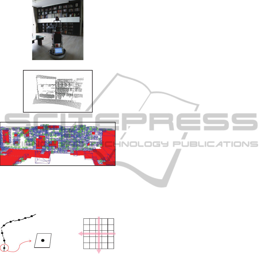
Fig. 2-(a) shows the experimental robot and a sec-
tion of the home environment used in the experiment.
The time-of-flight camera mounted on the robot scans
the environment at 5 frames per second (fps). Con-
sequently, the complete process of scanning a scene,
registering it into the previous scans, and constructing
the 3D map is done in 200 msec. A scan’s resolution
is 176×144. The section of the home environment
shown in Fig. 2-(a) requires 5 scans, and Fig. 2-(b)
shows the result of rendering the 3D points in a scan.
(Each point of the scan is represented as a 3D point,
and therefore can be directly rendered.) Fig. 2-(c)
visualizes the final 3D map representation, where the
planar features are colored in red. (The points that are
302
Jo Y., Jang H., Kim Y., Cho J., Lee H., Ik Eom Y. and Han J..
COOPERATION OF CPU AND GPU PROGRAMS FOR REAL-TIME 3D MAP BUILDING.
DOI: 10.5220/0003613203020304
In Proceedings of the 6th International Conference on Software and Database Technologies (ICSOFT-2011), pages 302-304
ISBN: 978-989-8425-77-5
Copyright
c
2011 SCITEPRESS (Science and Technology Publications, Lda.)
(a)
(b)
(c)
Figure 2: Indoor environment and its 3D map. (a) The robot
and a section of the environment. (b) The point clouds of
‘a’ scan for the section. (c) The 3D map representation with
the planar features included. (This is the output of the CPU
program.)
3 7 0
6
2
8
4
5
1
(b)
(a)
micro-plane
Figure 3: Micro-planes and normal computation. (a) A
micro-plane is presented by a point’s position and normal.
(b) A micro-plane’s normal is computed using the position
information of the neighboring points.
not included in the planar features are illustrated as
wireframe boxes containing the points.)
3 MICRO-PLANE EXTRACTION
In order to help the CPU detect the planar features of
the indoor environment, the GPU extracts the micro-
planes from the scanned points. For each point of a
scan, a micro-plane is extracted. As shown in Fig. 3-
(a), it is defined as an infinitesimal plane centered on
the point. To define its orientation, we have to com-
pute the normal. Fig. 3-(b) shows a block of 5×5
points in a scan. The normal of the center point (point
0) is computed as the cross product of the vector con-
necting points 1 and 3 and the one connecting points
2 and 4.
The GPU has a massively parallel processing ar-
chitecture such that hundreds of cores independently
operate on texels. A core is assigned to a texel to ex-
tract a micro-plane. The parallel architecture of the
GPU allows very efficient manipulation of large bulks
of data, i.e., 176×144 texels in a scan.
Unfortunately, a lot of noises are generated in the
extracted micro-planes, i.e., the points sampled from
a real-world plane may have different normals. For
the purpose of de-noising, the GPU program uses a
mean filter (Boyle and Thomas, 1988). In the current
implementation, the filtering process is iterated five
times. The parallel architecture of the GPU also fits
to the filtering algorithm.
The map building algorithm implemented by CPU
constructs a larger plane using a set of micro-planes.
The red-colored features shown in Fig. 2-(c) are the
planes extracted by the CPU algorithm. (Presenting
the map building algorithm is beyond the scope of this
paper.)
4 IMPLEMENTATION AND
EXPERIMENTAL RESULTS
GPU plays a key role in our study. This kind of
approach of solving non-graphics problems on GPU
is known as general purpose computation on GPU
(GPGPU). The micro-plane extraction and mean fil-
tering algorithms are implemented in CUDA (Com-
pute Unified Device Architecture) (Nickolls et al.,
2008).
The algorithms for micro-plane extraction and
mean filtering take about 5msec per 176×144-
resolution scan. For comparison, we also imple-
mented the same algorithms in CPU, and found they
take approximately 150msec, i.e., they are about 30
times slower than the GPU algorithm. Recall that our
goal is 5 fps map building, i.e., 200msec is assigned
to a scan. The CPU implementation makes it hard to
achieve the goal. It is because, in addition to micro-
plane extraction (and mean filtering), the module for
‘map building’ shown in Fig. 1 should also be done
within 200msec. Unfortunately, ‘map building’ typi-
cally takes more time than micro-plane extraction and
mean filtering.
Fig. 4 shows the experimental result for another
COOPERATION OF CPU AND GPU PROGRAMS FOR REAL-TIME 3D MAP BUILDING
303
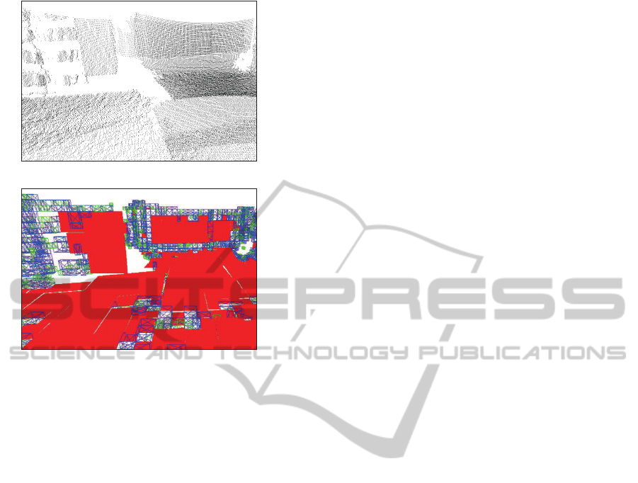
(a)
(b)
Figure 4: Another test result. (a) Point clouds. (b) 3D map.
section of the home environment. Fig. 4-(a) is the
rendering result of the input point clouds from multi-
ple scans, and Fig. 4-(b) shows the 3D map where the
planar features are colored in red. The entire process
of scanning, micro-plane extraction, mean filtering,
and map building takes about 70msec per scan.
5 CONCLUSIONS
A 3D map might be provided in advance to a mobile
robot, but it is not always possible especially for a dy-
namic environment. Therefore we need to construct
the map at real time. In our study, the home ser-
vice robot scans the environment five times per sec-
ond, and updates the map on the fly. Such real-time
performance is achieved largely due to GPU imple-
mentation of the micro-plane extraction and mean fil-
tering algorithms. The input point clouds are massive
(176×144 resolution) and independent of each other.
The parallel processing capability of many-core GPU
proves to satisfy the real-time constraint.
ACKNOWLEDGEMENTS
This research was supported by MKE, Korea un-
der ITRC NIPA-2011-(C1090-1121-0008) and the
National Research Foundation of Korea(NRF) grant
funded by the Korea government(MEST) (No. 2009-
0086684).
REFERENCES
Jang, H. and Han, J. (2008). Fast Collision Detection using
the A-Buffer. The Visual Computer, 24(7):659-667.
Boyle, R. D. and Thomas, R. C. (1988). Computer vision:
a first course. Blackwell Scientific Publications, Ltd.,
Oxford, UK, UK.
Nickolls, J., Buck, I., Garland, M., and Skadron, K. (2008).
Scalable parallel programming with cuda. Queue,
6:40–53.
ICSOFT 2011 - 6th International Conference on Software and Data Technologies
304
