
MODULAR DESIGN FOR SPACE ENGINEERING RESEARCH
PLATFORMS
Mark Post, Regina Lee and Brendan Quine
Earth and Space Science and Engineering, York University, 4700 Keele St., Toronto, Canada
Keywords:
Field robotics, Mobile robots, Embedded systems, Electronics.
Abstract:
In this paper, we describe a modular design approach that is used in developing several research platforms for
space engineering research at York University. We briefly describe three distinct research projects for space
science and engineering research: a 6kg micro-rover under development for the Northern Light mars lander
mission, a 50kg rover built by the York University Rover Team to compete in the annual University Rover
Challenge, and a 1U CubeSat design for nanosatellite technology development research. All three research
projects share a design philosophy to achieve modularity, efficiency, robustness and simplicity by adopting a
common embedded hardware configuration using COTS hardware and a simple control topology. An on-board
computer board stack based on a PC/104 or similar form-factor provides centralized control using an ARM
microcontroller. Payloads and application-specific components are added using robustSPI, synchronous serial,
and RS-485 interfaces, with provision made for ethernet and USB connectivity when needed. The software for
this system is is based on open-source compilers and operating systems and is also modular in nature, using
a portable base station GUI, wireless mesh networking between different systems, and JAUS messaging for
flexible component-level communications. The proposed design approach allows sharing of resources while
optimizing design features with cost-effective, readily-available commercial components for complex research
projects.
1 INTRODUCTION
The challenges of creating system designs for space
engineering research and education are often differ-
ent from those encountered in industry. To mini-
mize costs and development time, commercial-off-
the-shelf (COTS) components and free open-source
software (FOSS) tools are preferred for building sys-
tems for use in research and student projects. Addi-
tionally, the engineers tasked with building and pro-
gramming the robotic hardware are often students
with limited knowledge of embedded systems and
minimal hands-on experience, so using simple inter-
faces and design methodologies is generally benefi-
cial. In many cases, it is necessary to integrate net-
works of simple componentsin a manner that not only
keeps communications simple and efficient for pro-
totype robots such as in (Candini et al., 2009), but
also to allow sufficient flexibility for enlarging and
upgrading the systems later.
This approach must be balanced by the necessity
to design and build reliable systems that can tolerate
potentially hostile environments while operating.
Noise tolerance, thermal limitations, and ESD pro-
tection need to be considered for the system to be ro-
bust in practical use. As many universities, includ-
ing York University in Toronto, are now participating
in the development of microsatellites and nanosatel-
lites, such systems may also need to be operable in
the extremes of vacuum, temperature and radiation in
outer space. Successful nanosatellite missions using
off-the-shelf hardware such as CanX-2 (Sarda and C.,
2010) have proven that given good engineering prac-
tice, it is not always necessary to use very special-
ized hardware to operate in hostile or distant environ-
ments, and depending on the mission, simple radia-
tion shielding and temperature control may be suffi-
cient.
2 DESIGN CRITERIA
The following four criteria are proposed for the de-
velopment of an adaptable, mobile robotic research
platform.
427
Post M., Lee R. and Quine B..
MODULAR DESIGN FOR SPACE ENGINEERING RESEARCH PLATFORMS.
DOI: 10.5220/0003649804270436
In Proceedings of the 8th International Conference on Informatics in Control, Automation and Robotics (MORAS-2011), pages 427-436
ISBN: 978-989-8425-75-1
Copyright
c
2011 SCITEPRESS (Science and Technology Publications, Lda.)

1. Modularity. Parts of the system can be added and
removed as needed for the purpose at hand, but
the system uses common modules and interfaces
for multiple purposes.
2. Efficiency. Most space hardware is solar-
powered, and most mobile robotic hardware is
battery-powered, so minimizing power use and
weight is essential.
3. Robustness. Components and bus systems have
to tolerate environmental variations and extremes
that arise from the variety of conditions that may
be encountered.
4. Simplicity. For a research institution, hardware
must be simple to understand and flexible in op-
eration so that it can be applied to many different
levels of projects.
Recently, the rapid development of low-cost micro-
controllers and highly-integrated logic devices for the
mobile device market has made it possible to build
modular, general purpose robotic hardware for a frac-
tion of the cost and complexity needed even two
decades ago. Designing and constructing these sys-
tems in-house has the benefits of easy modification,
low cost, and a better overall understanding of the
system’s dynamics, and students can work in depth
with the system as part of their education. To lever-
age this capability, we propose a modular electronic
design philosophy for electronic systems that can be
used in a variety of research projects. The hardware
should be easily adaptable to different uses. System
modules should be easily field-replaceable and ser-
viceable. Electronic parts used in this system need to
be readily available for ease of development, tolerant
of noise and voltage in field conditions, and inexpen-
sive. Components in ball-grid array and other no-lead
packages should be avoided to facilitate soldering, re-
pair, and improve vibration resistance. Programming
should make use of open and freely-available tools to
ensure continuing availability.
2.1 Current Implementations
The motivation for designing a standardized set of in-
terfaces and implementation guidelines is that differ-
ent research groups with varying hardware require-
ments can share designs, hardware, and program code
so more time and effort can be spend on the re-
search itself as opposed to the hardware necessary
to accomplish it. This paper describes a framework
for field robotics that lends itself well to modular
robotic systems such as rovers with payloads, un-
manned aerial vehicles, sensor networks, and even
nanosatellites. The focus is on efficiency and mini-
mization so that physically small and solar-powered
systems can be built, but the embedded hardware is
centered on a modern ARM microcontroller that is
powerful enough to support a variety of autonomous
operating modes. This modular design is being put
to use in several student and research projects at York
University.
Foremostly, a micro-rover (or “µrover”) prototype
known as the Beaver is currently under development
for use in the Northern Light Mars Lander mission
(Quine et al., 2008), a Canadian Mars lander and rover
system instrumented to provide new information on
the Martian atmosphere, surface, and subsurface. The
6kg micro-rover is capable of autonomous operation
and is built on a four-wheel drive swing-arm suspen-
sion chassis with two science payload spaces at the
front and back. The first version of the Beaver was
tested at the Algonquin Radio Observatory in Novem-
ber 2010, and the results of testing have confirmed the
usability of the modular system. The uRover design is
based on a 10 x 10 x 20 cm form factor to accommo-
date PC/104 form factor boards, batteries, and associ-
ated hardware, and the on-board computer is based on
a low-power ARM microcontroller that uses routed
messaging for inter-component communications. A
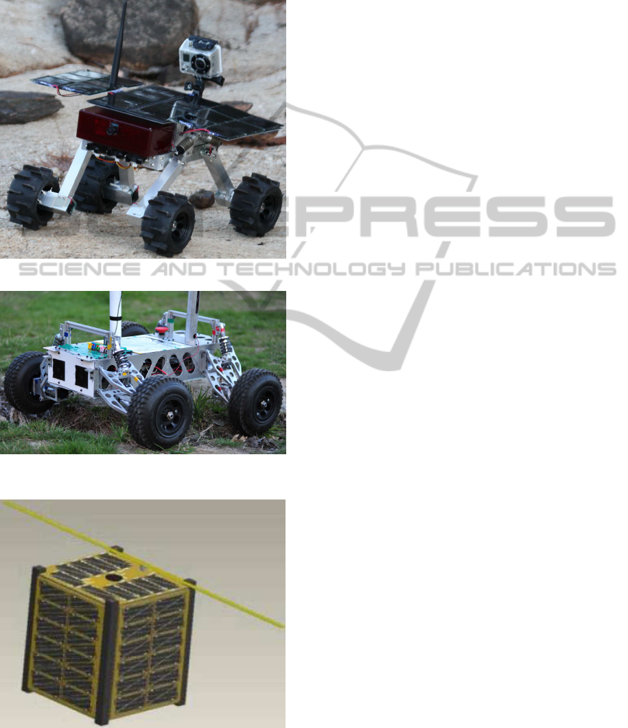
research prototype is shown in Figure 1 (a).
Also, The York University Rover Team (YURT)
is a student group that has achieved podium finishes
for all three years competing in the University Rover
Challenge held by the Mars Society. Each year, the
team builds a new 50kg rover based on the experi-
ence gained in previous years and uses it to perform
four distinct remotely-guided tasks in desert condi-
tions with rocky terrain and > 30
◦
C heat at the Mars
Desert Research Station in Utah, USA (Post and Lee,
2011). The modular system design described here has
both influenced and been influenced by the experi-
ences of YURT, and each generation of rover refines
the standards and implementation of the previous one.
Figure 1 (b) shows the rover developed for the 2011
competition, known as E.V.E. (Enhanced Vehicle Ex-
plorer)
Finally, the nanosatellite development program at
York University is in the process of designing a 1U
CubeSat (of size 10 x 10 x 10 cm) that follows the
modular embedded design philosophy. For a typi-
cal CubeSat application, external payload interfaces
and command routing is not necessary, as every com-
ponent is contained on the on-board computer stack.
The components are different but the engineering can
remain consistent and retain most of the compatibil-
ity with other robotic systems. A conceptual view
of the CubeSat when completed is shown in Figure
ICINCO 2011 - 8th International Conference on Informatics in Control, Automation and Robotics
428
1 (c). Planned future work includes development of
unmanned aerial vehicles similar to those described
in (Cho et al., 2007) using the same modular system.
(a) Beaver micro-rover prototype.
(b) YURT2011 competition rover E.V.E.
(c) York CubeSat nanosatellite concept.
Figure 1: Existing implementations of modular system.
3 HARDWARE ARCHITECTURE
To achieve the described flexibility in configuration
of the the embedded on-board computer (OBC) hard-
ware, a stack of printed circuit boards (PCB) is pro-
posed as the basis for the modular system. This OBC
stack includes a common motherboard for central-
ized control, and additional daughterboards that can
be added to suit the application. If more complexity
is needed, additional stacks can be added and linked
together.
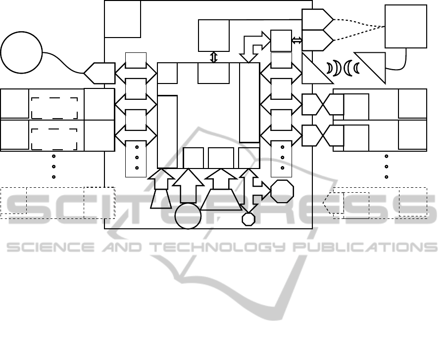
A diagram of proposed component and interface
organization in the modular system is shown in Fig-
ure 2. To date, most implementations have been
built by hand using through-hole components, which
makes the motherboards, daughterboards and pay-
loads larger and heavier. A surface-mount electronic
implementation in PC/104 form factor is currently un-
dergoing critical design review, and will be used for
the micro-rover prototype, while a slightly different
but compatible implementation is under development
for the nanosatellite prototype. The PC/104 form fac-
tor describes a stack of PCBs with pass-through 0.1“
64-pin and 40-pin headers, and was chosen because
it is a common standard for embedded systems in in-
dustry and robotics, and strikes a good balance be-
tween compactness and flexibility. The pinout is al-
tered to contain the communications interfaces de-
scribed here. The resulting board stack will look as
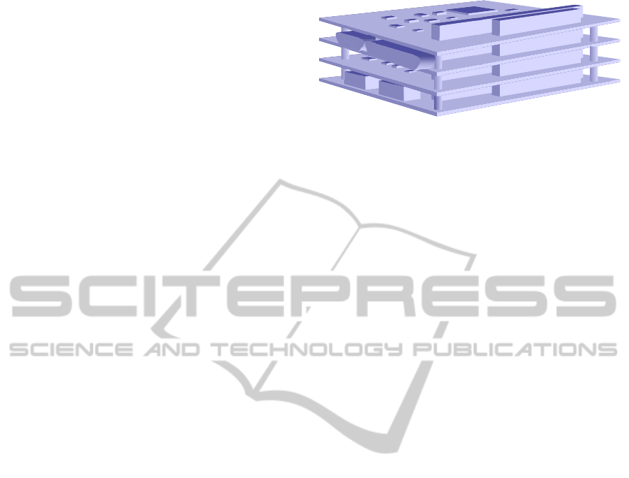
shown in Figure 3.
3.1 Control Topology
The proposed modular system is built around a pow-
erful central microcontroller on a single motherboard
in the OBC stack that is responsible for autonomy
and system coordination. Additional daughterboards
can contain a set of small component microcontrollers
that perform low-level tasks and can be customized to
suit different requirements. To make most effective
use of off-the-shelf components, the interfaces used
by rover systems have to be common enough to be
present on most modern embedded hardware, but still
well-suited for real-time robotic applications.
The standardized ARM architecture is preferred
for central microcontrollersas it is possible to use em-
bedded operating systems and program source code
that are easily ported between specific microcon-
trollers, with only the low-level hardware interfaces
requiring modification in some cases. In the case of
embedded Linux, these low-level interfaces are gen-
erally handled in the kernel and accessible by means
of user-space device interfaces. Currently, the Atmel
AT91RM9200 and AT91SAM9260 ARM9 microcon-
MODULAR DESIGN FOR SPACE ENGINEERING RESEARCH PLATFORMS
429
ARM
Microcontroller
NAND Flash
or MMC Card
Parallel
I/O
Motherboard
Inertial
Sensors
RS485
Driver
RS485
Driver
NOR
Flash
SPI 0
I2C Bus
RTC
Daughterboard 1
Daughterboard 2
SPI Chan. 1
SPI Chan. 2
Serial Port 1
Serial Port 2
Pin
Header
Pin
Header
Micro-
controller
Switching
DC-DC
Converters
Switching
DC-DC
Converter
Switching
DC-DC
Converter
Micro-
controller
Payload 1
Payload 2
Micro-
controller
Switching
DC-DC
Converter
Switching
DC-DC
Converter
Micro-
controller
Serial Port 0
Driver
Driver
SPI
Ctrl
USART
Ctrl
I2C
Ctrl
Memory
Ctrl
MII
Ctrl
Packet
Radio
Console
USB-
Serial
Micro-USB
Host PC
Packet
Radio
Ethernet
PHY
RJ-45
Jack
USB
Ctrl
USB Host
ISI
/GPIO
Parallel
I/O
USB
Other Payloads
Other Boards
in Stack
Motor Controllers
and Drivers
External Sensor
Interfaces
CMOS
Camera
Interface
USB
Peripherals
Figure 2: Diagram of modular system topology.
trollers are used, though a variety of automation-
oriented ARM microcontrollers are available, most
notably the Cortex-M3 and M4 series that use the
Cortex Microcontroller Software Interface Standard
(CMSIS), and will be used in future implementations.
Due to the master-slave paradigm used in the mod-
ular system, only one central ARM motherboard is
usable in each OBC stack, but this limitation has not
caused problems as ARM microcontrollers compara-
ble in power to desktop computers are now available,
and multiple OBC stacks can be used on a vehicle
if needed. As per CubeSat standards, the 1U Cube-
Sat under development at York University is based
on the PC/104 form factor with an ARM-based cus-
tom OBC stack. The YURT rovers use an ALIX em-
bedded router motherboard with external serial inter-
faces rather than an ARM microcontroller and hard-
ware stack, but future implementations may use ARM
systems for better power efficiency and higher inte-
gration with other systems.
The component microcontrollers can be inexpen-
sive 8-bit microcontrollers for motor control, sen-
sor monitoring, and payload management, or more
complex controllers if required. The microcontroller
most often chosen for this role is the Atmel AVR
8-bit RISC architecture, which is easily in-system
programmable using the GNU C/C++ compilers and
open-hardware SPI programmers. Modularity is
achieved by attaching these to the central ARM mi-
crocontroller using simple serial and parallel bus stan-
dards and pin headers, or D-sub connectors for exter-
nal connections. The use of small microcontrollers in
this manner allows hardware customization without
having to change the central controller in the system
or its motherboard, which is often the most complex
and costly component in a small robotic system.
To maximize reliability, “multiple-hop“ commu-
nications are avoided. SPI channels are connected
directly to the central microcontroller and serial in-
terfaces are connected via a MAX489 or similar se-
rial buffer IC with high voltage and ESD protection.
Damage to robotic components, which is often caused
by ESD and electrical shorts, is isolated by means
of the communication buffers and is less likely to
spread to adjacent components. Programmable logic
devices such as FPGAs and CPLDs is avoided, since
these devices often require proprietary software and
hardware to program, and can consume significantly
more power than microcontrollers of similar capabil-
ity. However, low-power CPLD devices can be used
where microcontrollers are less well-suited, such as
high-speed encoding and decoding tasks.
3.2 Board-to-Board Communications
All signals are carried between OBC boards as shown
in Figure 3 via standard 0.1“ pin headers. This fa-
cilitates connection between boards and wires, and
makes debugging easy. Proprietary connectors are
often hard to test and usually are not compatible be-
tween manufacturers and sizes. Due to the resiliency
of using separate transmit, receive, clock, and frame
ICINCO 2011 - 8th International Conference on Informatics in Control, Automation and Robotics
430
synchronization wires, SPI is preferred for board-to-
board communication at high bit rates, though a syn-
chronous serial interface with clock like also provides
a reliable connection. Communication with payloads
is generally achieved using 8-bit serial communica-
tions, which is the most common low-level way to
interface with embedded systems, but TTL serial in-
terfaces are also broken out through the pin headers
for use in used in board-to-board communications.
For debugging and system recovery purposes, one se-
rial port should be designated as a system console
or debug port, and this is usually available via USB-
to-Serial converter IC for convenience in connecting
portable PCs. GPS Devices and embedded radios
are often serial devices that can be included in the
OBC stack. Though very common, high speed per-
sonal computer buses such as PCI and PCI-Express
do not present significant benefit to low-speed embed-
ded systems with limited I/O resources and integrated
controllers.
The number of Serial and SPI devices is only lim-
ited by the number of SPI and Serial interfaces on
the ARM microcontroller. Provision is made on the
board headers for at least four serial interfaces and
four SPI interfaces with chip selects. Board headers
do not make use of line drivers to save power. There
have been no problems using direct pin connections
between boards so long as the housing for the OBC
stack is sealed from sources of ESD and contami-
nants. The York CubeSat manages all onboard sys-
tems through a mixture of SPI and synchronous TTL
serial interfaces.
For register-level access to onboard sensors and
peripherals, I
2
C is a synchronous bus widely used for
register-level communications to multiple embedded
ICs, but because it must embed addressing, bus ar-
bitration, and multi-master capability using only two
wires and a simple protocol, it is very sensitive to in-
terference and noise from the environment. To maxi-
mize reliability, trace lengths to the I
2
C host must be
minimized and daughterboardsand payloads must use
a microcontroller to transfer data to SPI or serial bus
lines from the I
2
C device.
For interfacing high-bandwidth devices, CMOS
and CCD cameras are interfaced directly to the cen-
tral ARM microcontroller via either a parallel bus of
general-purpose input-output (GPIO) pins or if avail-
able, a dedicated image sensor interface (ISI). Both
volatile (RAM) and non-volatile (Flash) memory is
interfaced by means of dedicated memory hardware,
i.e. RAM interface, NAND Flash interface, and SDIO
bus. Nearly all modern ARM microcontrollers have
dedicated memory interfaces.
Figure 3: Rendering of PC/104 stack as used on micro-
rover.
3.3 Payload Communications
For external payload communications, RS-485 has
been selected as the standard of choice. The RS-485
interface is an industry standard for differential-pair
serial communications to multiple transceivers, and is
already used on many robotic systems. It may be used
in either half-duplex mode (separate transmit and re-
ceive pairs) or full-duplex mode (pairs connected),
but full-duplex with a single master is preferred to
avoid byte collisions and the need for bus arbitration.
RS-422 devices are also compatible with this inter-
face.
Additionally, the RS-485 interface is designed for
bidirectional communication with up to 32 devices
on a single bus, the number of potential payloads
is high enough to accommodate large robotic sys-
tems. The 2011 YURT rover uses an RS-485 bus
to control six arm motor control boards from a sin-
gle serial interface. While RS-485 can operate at 10
megabits per second at 40 feet and 100 kilobits per
second at 4000 feet, to allow low-speed microcon-
trollers to communicate reliably, the standard baud
rate of 115200 baud is used as the default speed unless
higher bandwidth for the specific payload is required.
For long-distance disconnectable operation, an RJ-45
jack and twisted-pair cabling also provides good per-
formance. For extreme environments, an additional
pair is used to transmit a clock signal for synchronous
operation to ensure reliable transmission. With the
exception of high-bandwidth devices such as optical
sensors, memory, and media interfaces, these serial
links are more than capable of real-time command
transmission. As no standardized D-sub pinout has
been accepted for RS-485 communications, one was
created to suit the modular system with differential
clock (CK) power supply, and interrupt pins. The ex-
ternal interfaces are situated on a board in the OBC
stack with line drivers and external DE9 connectors.
To pass GPIO signals and parallel buses, DB25 con-
nectors are useful with each pin buffered against ESD
and high voltage also.
The very common RS-232 serial port, while still
MODULAR DESIGN FOR SPACE ENGINEERING RESEARCH PLATFORMS
431
present in a huge number of devices, is not tradition-
ally compatible with RS-485 interfaces and is less ef-
ficient as it is based on negative logic and ±5− 15V
signal levels. A dedicated converteris the best method
for interconnection. However, given that most mod-
ern hardware uses only ±5−7V and has thresholds at
1V, it is possible for RS-232 and RS-485 devices to
communicate directly if required, for example, in new
hardware testing or field debugging using RS-232.
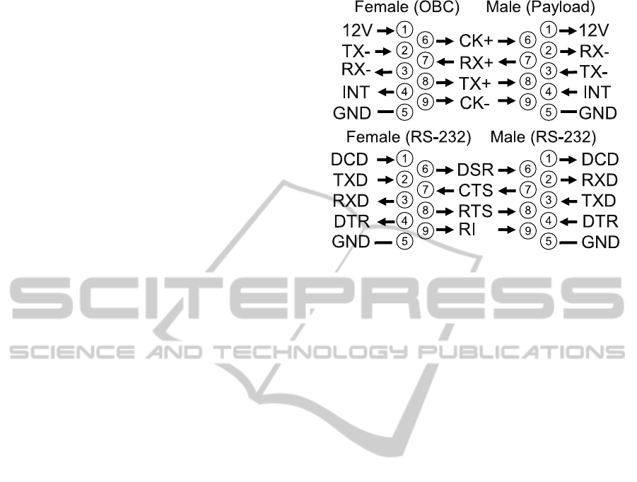
The payload pinout, shown in Figure 4, was chosen to
be electrically compatible with RS-232 for this reason
and to increase safety in case of accidental RS-232
connection. The RS-485 TX-(Z) and RX-(B) pins are
connected to RS-232 RX and TX respectively to in-
vert logic levels, TX+(Y) and RX+(A) are connected
to RS-232 CTS and RTS respectively to serve as a
ground reference. The CTS and RTS pins must be al-
lowed to float to ground, and if the hardware does not
allow this, TX+(Y) and RX+(A) must be connected
to the RS-232 ground instead. This method works
well using a MAX489 transceiver IC and is consid-
ered an option for debugging and testing with RS-232
hardware and purpose-built serial interfaces. But it is
less efficient than only RS-485 communications and
breaks the RS-232 specification by referencing sig-
nal levels to ground rather than ±5 − 15V. Newer
RS-232 hardware and USB to RS-232 converters that
have low signal voltages are useable, but older high-
voltage RS-232 hardware may be unsafe to use as the
RS-485 transceiver used must be able to tolerate the
signal voltages.
For devices other than system payloads, USB can
be used for COTS hardware, since the interface is
present on many embedded devices, but is gener-
ally restricted to hot-pluggable external hardware and
mass storage devices rather than hard-wired onboard
peripherals. Ethernet can also be used, but has sig-
nificant programming and routing overhead, so it is
preferred as an external network interface for de-
velopment purposes. Other industrial standards for
communications such as CAN, LIN, Firewire and
Spacewire, though often used in other systems for
reliability-critical applications (Torre et al., 2010), are
not present on the majority of embedded devices and
are not generally used in the interest of easy interop-
erability. The Spacewire bus in particular, designed
and used for space hardware, is very fast and robust,
but is only implemented in hardware on a very small
set of radiation-hardened devices which are very rare
and expensive.
Figure 4: Payload DE9 connector and RS-232 pinouts.
3.4 Radio Communications
Wireless communications between mobile robots and
control stations is a critical component in applications
requiring remote control or monitoring. To simplify
terrestrial work, it is desirable to use license-free ISM
bands or amateur radio bands when communicating.
The frequency must also be high enough to support
high bit rate communications, preferably at least the
basic system rate of 115200 baud. The 2.4GHz band
is by far the most popular, but higher frequency sys-
tems have lower range and worse non-line-of-sight
(NLOS) characteristics, and this band has also be-
come very crowded with interference from consumer
electronic devices. Another option is the 433MHz
band and below, which can be used by amateur radio
operators, but limits data rates on most radio hard-
ware to 38400 baud and lower. The 900MHz ISM
band is a good medium between these options, as it
provides reasonable range and NLOS characteristics,
can support bit rates above 115200 baud, and is not
used excessively by consumer devices.
Another consideration is the need for multi-point
communications and routing. There are many situa-
tions when several mobile robots need to stay in com-
munications with each other and with base station
units, but relative movement, terrain variations and
ambient conditions make static network structures un-
reliable. One popular solution to this is the mesh net-
work, which allows multiple transceiversto route data
to each other using dynamically maintained and self
healing network structures. The best known indus-
trial mesh network specification is ZigBee, which is
used frequently in sensor mesh networks but requires
a dedicated coordinator and router nodes which lim-
its the flexibility of the network. The B.A.T.M.A.N.
ICINCO 2011 - 8th International Conference on Informatics in Control, Automation and Robotics
432

(better approach to mobile ad-hoc networking) rout-
ing protocol was recently added to the Linux kernel to
allow mesh networking over wireless LAN networks,
but is not designed for low-level serial hardware.
To provide a long-range serial mesh networking
system, the Digi XBee PRO Digimesh 900 serial ra-
dio module is used frequently on modular research
hardware, one exception being the YURT rover which
requires high camera data rates and uses Ubiquiti
XR9 900MHz mini-PCI network cards, with XBee
modules as a fallback if needed. The Digimesh proto-
col is proprietary, but allows mesh networking with-
out a central coordinator. As these radio modules
use a well-known form factor, replacing them with
2.4GHz modules or custom modules that change fre-
quency, range, and protocol is simple.
Future work in this area includes the development
of an open-hardware transceiver module and purpose-
designed mesh network protocol. For higher-power
radio systems, an OBC daughterboard can be used.
The advantage of using simple serial communications
rather than Ethernet, Wireless LAN, or other IP com-
munications standards, is that a wider variety of ra-
dio systems and communications frequencies can be
used, up to and including S-band and UHF radio sys-
tems for space hardware. It is also easy to encapsu-
late serial communications over IP-based systems if
desired.
3.5 Power
Onboard batteries are expected to be used for power
storage, and can be charged from solar panels or other
sources. For small rovers and aerial vehicles, a sin-
gle cell or stack of lithium-ion (Li-Ion) cells in series
must be used to achieve high power densities. Since
the batteries must be balance-charged for longevity,
the electronics can run off the bottom cell in the stack,
which is done on the micro-rover prototype. For large
rovers, nickel metal hydride (NiMH) battery packs
can be used for higher stability and environmental
tolerance, and 24V is used for powering larger drive
motors with the rest of the electronics either being
powered by a separate 12V battery as previous YURT
rovers have been, or by using heavily-filtered switch-
ing converters tolerant of high voltages. Battery volt-
age and current monitoring is done via analog-to-
digital converters, which are present on most modern
microcontrollers and ideally are present on the central
ARM microcontroller. In-depth testing of Li-Ion cells
(Navarathinam et al., 2011), NiMH battery packs and
high-current DC-DC power converters has been done
to verify performance in extreme environmental and
operational conditions.
With the availability of low-cost highly-integrated
switch-mode converters, it is feasible for each mod-
ule in the system to convert DC power from the sys-
tem battery to whatever level is needed. Daughter-
boards in the OBC generally use the system battery
for power as well as regulated 3.3V and 5V sup-
ply rails provided by the motherboard. The choice
of power supply is important. Simple linear volt-
age regulators that are commonly used on microcon-
troller boards become less efficient relative to the in-
put/output voltage difference, and are unsuitable for
use in vacuum or high-temperature environments as
the only mechanism for cooling is direct radiation of
heat. To achieve the highest power conversion ef-
ficiency possible, switching step-down (buck) con-
verters are used, if at all possible, rather than step-
up (boost) converters. Using only low-dropout buck
converters with high input voltage tolerance makes it
possible to achieve system efficiencies close to 90%.
Also, each module is responsible for filtering its own
load noise via capacitor-inductor networks to avoid
injecting power supply transients back into the OBC.
Zener diodes should also be used to protect from ESD
and over-voltages.
3.6 Motor Control
An essential element of most robots is electronic mo-
tor and actuator control. Traditionally, brush DC mo-
tors with mechanical commutation have been used
for robotic movement due to their cost-effectiveness
and simplicity of implementation, and brush DC mo-
tors are still dominant in the marketplace. However,
the recent availability of high-speed microcontrollers
and integrated drive bridges have made brushless DC
motors, which require external electronic commuta-
tion, increasingly popular. Brushless DC motors have
generally higher efficiency and longevity due to the
lack of mechanical brushes and are preferred for haz-
ardous environments and space applications, but re-
quire a different control method usually considered
incompatible with brush DC (Lee et al., 2003).
Ideally, both BLDC and DC motors could be
driven with only software changes, so any changes to
the system could be made by a microcontroller. Many
small microcontrollers are suitable for implementing
feedback and control of motors, and some PIC and
AVR models include dedicated hardware for this pur-
pose, while still being programmable in C and using
minimal power. Flexible designs for multiple motors
have been achieved using FPGA hardware and DSP
ICs, such as in (Zerigui et al., 2007). While this ap-
proach provides high control speeds, it requires more
power to run the FPGA and introduces significant
MODULAR DESIGN FOR SPACE ENGINEERING RESEARCH PLATFORMS
433
complexity in design and programming. To enable
a common system to drive both brush DC and brush-
less DC motors, a hybrid approach is required. DC
motors are usually controlled by using a fixed input
and pulse-width modulation (PWM) to manage the
amount of total power provided to the motor. Brush-
less DC motors are controlled by shunting power to
different motor coils (or ”phases“) one at a time in
synchronization with rotor speed, usually measured
by Hall sensors, and speed control is achieved by
changing the time that power is shunted. Both sys-
tems usually use field-effect transistors (FETs) in a
half-bridge configuration to control current flow, two
for a brush motor in the ”H-bridge“ configuration, and
one for each phase of a brushless motor. Brushless
motors usually have up to three phases, so a hybrid
controller can be built with three such half-bridges.
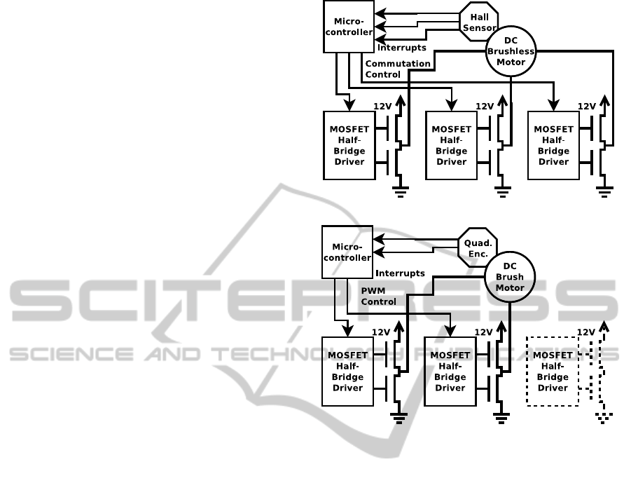
Figure 5 shows the hybrid system in both brush-
less DC (a) and brush DC (b) configurations. For
three-phase brushless use, a single set of three half-
bridges are cycled in sequence to supply power to
the three motor phases, while for brush use, two of
these form an H-bridge to supply pulse-width mod-
ulated DC power to the motor. Control feedback is
via a 3-phase Hall sensor in the brushless case and
bridges are commutated by setting GPIO lines, while
a quadrature (Gray code) encoder is used in the brush
case and pulse-width modulation control is used in
hardware. The drive controller 12V is assumed to be
the drive voltage in this diagram, but any appropriate
motor voltage can be used. Each motor requires the
use of one set of drive bridges, though a fast micro-
controller can usually drive more than one bridge at a
time. For small mobile robots and rovers, all needed
drive motor controllers can usually be implemented
on an OBC daughterboard, but for larger robots, the
drivecontroller is implemented as an external payload
to gain more space and better isolation. A prototype
of this hybrid system has been built for the micro-
rover, and shows promise for larger systems as well.
4 SOFTWARE ARCHITECTURE
In order to benefit from and support the open-source
community, and to ensure that the basis for the system
remains freely available and up-to-date, open-source
OS software and the GNU compiler collection (GCC)
is preferred to form the software base for the modu-
lar system. It is assumed that most mobile platform
software will have to control actuators, read sensors,
and communicate with a base station, a set of cen-
tral control programs for autonomous operation, or
both with system coordination occurring on the cen-
(a) Brushless Motor Configuration.
(b) Brush DC Motor Configuration.
Figure 5: DC motor controller basic configurations.
tral ARM microcontroller. The YURT rover (Post and
Lee, 2011) and micro-roverprototype are good exam-
ples of this kind of a system, as is the example is given
in (Marosy et al., 2009). As such, a robust multitask-
ing framework and a routing and command handling
system are essential to reliable operation.
The software for the system is stored in NAND
flash memory on the microcontrollers and on redun-
dant NAND and NOR flash devices on the mother-
board. NAND flash is the most common and provides
large storage capacity, while NOR flash devices can
store only a few megabytes but may be more resis-
tant to radiation and corruption (Farokh Irom, 2008).
To mitigate the risks of software corruption, in the
event of a boot failure the bootloader for the cen-
tral ARM microcontroller will switch between two
kernel/filesystem images. It is possible for the cen-
tral ARM microcontroller to boot from the smaller
failover device and retain sufficient capacity to re-
program internal component microcontrollers as re-
quired using SPI. Implementation of error-correction
codes is also proposed for improving storage reliabil-
ity, though it would have to be done either in software
or on an external logic device such as a programmable
ICINCO 2011 - 8th International Conference on Informatics in Control, Automation and Robotics
434

logic device (PLD). For NAND flash devices, the re-
cent addition of UBIFS to the Linux kernel provides
error detection and wear-leveling for NAND devices,
and currently appears to be the best option for NAND
devices in Linux.
4.1 Operating Systems
Direct-to-hardware programmingon the central ARM
microcontroller is possible, but an embedded operat-
ing system (OS) is usually used in research applica-
tions to to expedite software development and sim-
plify hardware interfacing. The Emdebian Linux OS
has been used for most of the existing development
work, and other FOSS systems are being investigated
for real-time flight hardware implementations such as
Linux with Xenomai for real-time support and FreeR-
TOS as a standalone real-time framework.
Customized Linux kernel patches and drivers that
implement user-space support for the embedded OBC
peripherals such as the RS-485 interfaces, SPI con-
trollers, and I2C sensors have been developed to pro-
vide hardware integration, and a set of dedicated li-
braries for 8-bit AVR microcontrollers has been cre-
ated to assist in programming component applications
for this system. The software for onboard systems has
been developed entirely in C and C++ for efficiency
and minimal code size. Other languages can be run
on resource-constrained hardware such as real-time
Java, and using a Linux environment enables the use
of Python as well. These will be retained as options
for future research.
For overall control and monitoring of remote sys-
tems at the base station, a graphic user interface (GUI)
has been developed using Java, with the philosophy
that it must be portable to whatever OS is used at the
base station, but need not run on resource-constrained
embedded hardware. The GUI development is based
on the work of the York University Rover Team, who
have been steadily improving their base-station GUI
concept for each generation of remotely-controlled
rover. The GUI integrates system health monitor-
ing, GPS localization, joystick movement control, and
camera displays for convenient use of the system op-
erator.
4.2 JAUS Messaging
For designs where only a few microcontrollers are
fixed in connection such as most nanosatellites, sim-
ple byte-by-byte protocols work fine, but for large
systems with multiple, changeable interfaces, a flexi-
ble message routing and communications protocol is
necessary. The routing system and protocol used cur-
rently for robotics is based on the Joint Architecture
for Unmanned Systems (JAUS), a messaging system
that groups similar or associated capabilities of a sys-
tem together and provides a consistent method of or-
ganizing subsystems (The joint architecture for un-
manned systems working group, 2007). The JAUS
structure can be considered close to the minimum of
functionality for universal point-to-point communica-
tions in a multi-device system. Although JAUS does
not specify implementation details, the JAUS refer-
ence implementation has been used as the basis for
the OpenJAUS project, an open-source framework for
remote operation of robotic systems that is portable to
a wide range of platforms.
The JAUS architecture is a tree structure, where an
entire system is composed of subsystems, each con-
taining nodes, each containing components, which
can have several redundant component instances. For
the architecture we are describing, an individual robot
represents a subsystem, a central ARM microcon-
troller represents a node and a microcontroller at-
tached to that controller represents a component,
which services a finite set of commands and may have
redundant systems on the same bus. More than one
central controller node can be present on a robot, and
each node must run a node manager for routing com-
munications to components, which is currently imple-
mented as the OpenJAUS node manager. As JAUS
commands can be large in scope and parsing require-
ments, microcontroller components can use custom
small-footprint commands for simple tasks. By us-
ing only a small set of commands for each microcon-
troller, most components are capable of sending and
receiving basic commands using JAUS natively, and
additional functionality is easy to implement.
The advantages of JAUS messaging between com-
ponents is that each node or component can initiate
messages to any other part of the system. While con-
trol is usually centralized in autonomous robots, the
capability of ”bypassing“ the central controller and
communicating directly between components using
only the node manager is sometimes useful and pro-
vides failover capabilities. However, the node man-
ager on each node must be very stable and should
be restarted if abnormal program behavior is noticed.
For ease of debugging, a ”console“ mode is used on
microcontrollers with sufficient flash memory, so that
by entering an escape sequence (commonly the AT
escape sequence ”+++“) a simple serial text console
can be used to send commands and check the status of
the microcontroller using ASCII keystrokes. This al-
lows easy field testing of components without requir-
ing a full JAUS implementation to be present. De-
velopment of JAUS-compatible code for the micro-
MODULAR DESIGN FOR SPACE ENGINEERING RESEARCH PLATFORMS
435

rover prototype is proceeding, and may be used in the
YURT rover in future as well.
5 CONCLUSIONS
In this paper, we briefly introduced three distinct
space engineering research projects at York, namely
micro-rover development, the York University Rover
Team’s larger scale Mars rover prototype design and
a 1U CubeSat-based nanosatellite design. In all three
distinct research projects, we aim to design mobile
platforms with a level of autonomy and simplicity
with distinct mission objects for each project. The
micro-rover is designed for Mars environment with
full autonomy and redundancy. The YURT rover
is designed each year to complete at the University
Rover Challenge with minimal autonomy, but with
flexibility for four separate tasks. The 1U CubeSat
is designed to demonstrate nanosatellite technologies
currently under development at York University.
The common design approach we have taken in
developing the above research platforms is the mod-
ularity and expandability in hardware and software
design. We described a centralized control topology,
in particular OBC design and communication proto-
cols, and introduced a subsystem design methodology
making use of highly-integrated commercial-off-the-
shelf (COTS) parts and low-cost components. In mo-
bile robots, the motor controllers provide selectable
brush or brushless DC motor management, while in a
satellite platform, the same design approach can drive
reaction wheels. A software architecture based on
open componentswas also developedwith modularity
in mind. In mobile platforms, mesh networking and
the JAUS structure was adopted to accommodate ef-
ficient point-to-point messaging communications. In
future, we plan to implement the proposed modular
design concept in other projects such as unmanned
aerial vehicles and distributed sensors for navigation,
mapping and remote sensing applications.
REFERENCES
Candini, G. P., Paolini, E., and Piergentili, F. (2009). Design
and manufacture of a low cost educational hexapod
rover. Acta Astronautica, 65(3-4):525 – 536.
Cho, A., Kim, J., Lee, S., Choi, S., Lee, B., Kim, B., Park,
N., Kim, D., and Kee, C. (2007). Fully automatic
taxiing, takeoff and landing of a uav using a single-
antenna gps receiver only. In Control, Automation and
Systems, 2007. ICCAS ’07. International Conference,
pages 821 –825.
Farokh Irom, D. N. N. (2008). Radiation tests of highly
scaled high density commercial nonvolatile flash
memories. Technical report, Jet Propulsion Labo-
ratory, California Institute of Technology, Pasadena,
CA.
Lee, J., Choi, J., Chung, J., and Lim, J. (2003). Design
and implementation of integrated drive circuit for a
small bldc motor. In Electrical Machines and Systems,
2003. ICEMS 2003. Sixth International Conference,
volume 2, pages 491 – 494 vol.2.
Marosy, G., Kovacs, Z., and Horvath, G. (2009). Effective
mars rover platform design with hardware / software
co-design. In Design and Diagnostics of Electronic
Circuits Systems, 2009. DDECS ’09, pages 148 –151.
Navarathinam, N., Lee, R., and Chesser, H. (2011). Charac-
terization of lithium-polymer batteries for cubesat ap-
plications. Acta Astronautica, 68(11-12):1752 – 1760.
Post, M. and Lee, R. (2011). Lessons learned from the
york university rover team (yurt) at the university
rover challenge 2008-2009. Acta Astronautica, 68(7-
8):1343 – 1352.
Quine, B., Lee, R., and Roberts, C. (2008). Northern light
- a canadian mars lander development plan. In Con-
ference Proceedings of CASI ASTRO 2008, Montreal,
Canada.
Sarda, K. and C., G. (2010). Canadian advanced nanospace
experiment 2 on-orbit operations; two years of push-
ing the nanosatellite performance envelope. In Con-
ference Proceedings of CASI ASTRO 2010, Toronto,
Canada.
The joint architecture for unmanned systems working group
(2007). Jaus reference architecture specification, vol-
ume ii, part i. http://www.openjaus.com/support/jaus-
documents.
Torre, A. D., Finzi, A. E., Genta, G., Curti, F., Schirone, L.,
Capuano, G., Sacchetti, A., Vukman, I., Mailland, F.,
Monchieri, E., Guidi, A., Trucco, R., Musso, I., and
Lombardi, C. (2010). Amalia mission lunar rover–the
conceptual design of the team italia rover, candidate
for the google lunar x prize challenge. Acta Astronau-
tica, 67(7-8):961 – 978.
Zerigui, A., Wu, X., quan Deng, Z., and Yu, K. (2007).
Common hardware design for (2n+2, 0*n*3) wheels
mobile rover. In Robotics and Biomimetics, 2007. RO-
BIO 2007, pages 712 –716.
ICINCO 2011 - 8th International Conference on Informatics in Control, Automation and Robotics
436
