
SCENE TRANSITION NETS SIMULATOR FOR MULTI-ASPECT
MODELING OF DISCRETE-CONTINUOUS HYBRID SYSTEMS
Takeshi Tateyama
1
, Seiichi Kawata
2
, Yoshiki Shimomura
1
, Kentaro Watanabe
1
and Ryosuke Chiba
1
1
Graduate School of System Design, Tokyo Metropolitan University, Asahigaoka 6-6, Hino-shi, Tokyo, Japan
2
Advanced Institute of Industrial Technology, Higashi-Ohi 1-10-40, Shinagawa-ku, Tokyo, Japan
Keywords:
Discrete-continuous hybrid systems, Simulation, scene transition nets (STNs), Manufacturing systems,
Multi-aspect modeling.
Abstract:
Scene Transition Nets (STN) are graphical modeling tools and simulators for discrete-continuous hybrid sys-
tems. Designers have previously built complex STN models of large-scale systems on the basis of a single
aspect. However, many large-scale systems consist of several sub-systems designed for different purposes and
based on different aspects. In addition, these subsystems are complexly intertwined with each one another.
For verifying the behavior of such complex systems in simulations, it is necessary to construct multiple STN
models of the subsystems, integrate them by taking into account the relationships among the subsystems, and
simulate them in parallel. Kawata has proposed ”multi-aspect modelingh using STNs in order to realize above-
mentioned modeling concepts. However, the interaction of the sub-STN models with other models is difficult
according to the basic STN concepts. This shortcoming interferes with the practical implementation of multi-
aspect modeling. The authors overcome this shortcoming by enabling the sharing of the state variables of the
actors (actors correspond to tokens in Petri nets). Called ”actor-link”, the simple concept enables to construct
complex layered and parallel structures of STNs and perform multi-aspect modeling. The experimental results
for the modeling and simulation of certain complex industrial systems demonstrate the effectiveness of the
proposed method and simulation tool.
1 INTRODUCTION
Simulation is an effective technique for verifying the
behavior of complex systems such as manufacturing
systems and chemical plant systems. However, many
complex industrial systems are actually combinations
of both continuous systems and discrete-event sys-
tems and are called ghybrid systems.h Hence, it is
difficult to model and simulate such systems by us-
ing only the modeling methods applicable to contin-
uous systems (e.g., differential equations) or those
used discrete-event systems (e.g., Petri nets(Murata,
1989)). Kawata et al. have proposed scene transi-
tion nets (STNs)(Kawata et al., 1994a)(Kawata et al.,
1994b) as graphical modeling and simulation tools for
discrete-continuous hybrid systems. Although STNs
are based on the concept of Petri nets, in STNs, de-
signers construct models of continuous systems us-
ing differential equations and then embed them into
discrete-event system models. By using STNs, de-
signers can easily construct models of hybrid sys-
tems and conduct simulations. STN programming re-
quires STN designers to possess considerable object-
oriented programming skills and excellent knowl-
edge. In our study, we aim to develop an gSTN graph-
ical user interface (GUI) simulator(Tateyama et al.,
)(Tateyama et al., 2010)h that will enable designers to
easily and graphically edit and simulate STN models.
System designers have previously built complex
STN models of large-scale systems on the basis of
a single aspect. However, many large-scale systems
consist of several subsystems designed for different
purposes and based on different aspects. In addition,
these subsystems are complexly intertwined with one
another. For verifying the behavior of such complex
systems in simulations, it is necessary to construct
multiple models of the subsystems, integrate them
by taking into account the relationships among the
subsystems, and simulate them in parallel. Kawata
et al. have proposed ”multi-aspect modelingh using
STNs(Kawada et al., 1996) in order to realize the
abovementioned modeling concepts. In this model-
ing method, it is necessary to create models of inter-
actions among submodels. However, an actor can be
467
Tateyama T., Kawata S., Shimomura Y., Watanabe K. and Chiba R..
SCENE TRANSITION NETS SIMULATOR FOR MULTI-ASPECT MODELING OF DISCRETE-CONTINUOUS HYBRID SYSTEMS.
DOI: 10.5220/0003650104670475
In Proceedings of the 8th International Conference on Informatics in Control, Automation and Robotics (MSIE-2011), pages 467-475
ISBN: 978-989-8425-75-1
Copyright
c
2011 SCITEPRESS (Science and Technology Publications, Lda.)
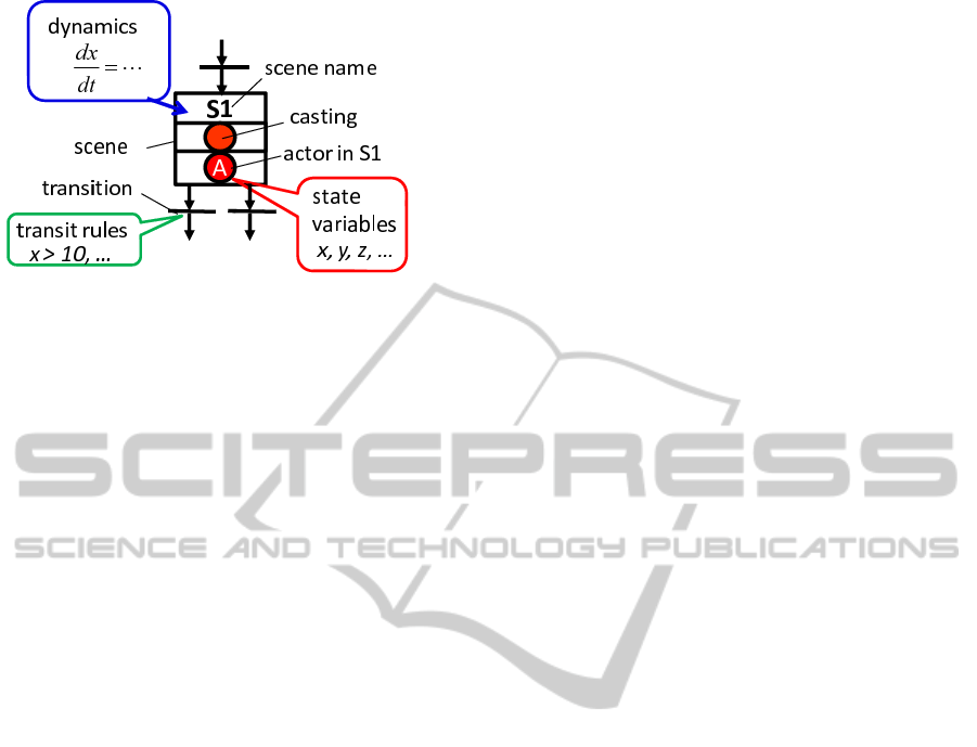
Figure 1: STN components.
present only in one scene at a time and cannot com-
municate with other actors according to the basic STN
concept. These shortcomings make the interaction of
the sub-STN models with other models difficult. As
a result, this problem interferes with the practical im-
plementation of multi-aspect modeling.
In this study, the authors overcome this shortcom-
ing by enabling the sharing of the state variables of
the actors. This concept is called ”actor-link”. In ad-
dition, the authors implement the concept in the STN
GUI simulator as useful functions so that the design-
ers can easily apply the modeling methods to a wide
variety of systems. The proposed method and tool
enable system designers to construct STN models of
complex systems as a combination of simple submod-
els based on different aspects and make large-scale
modeling and verifications by multiple professionals
easy. Our tool also assists professionals in verifying
the behavior of complex systems from many different
aspects and meet the users’ requirements using graph-
ical STN simulations.
The experimental results for the modeling and
simulation of certain complex industrial systems
demonstrate the effectiveness of the proposed method
and tool.
2 SCENE TRANSITION NETS
(STN)
An STN is a graphic modeling method for discrete-
continuous hybrid systems: it uses the concept of gac-
torsh and gscenes.hIt is based on the Petri net, which
is a modeling method for discrete event systems. It
can express hybrid systems by using the concept of
a Petri net and by inputting differential equations in
scenes. In an STN, an actor corresponds to a sub-
system of a hybrid system. Designers can simulate
interactions between the subsystems that act in paral-
lel by describing the models by using object-oriented
programming languages (e.g. Smalltalk, JAVA). An
STN comprises actors, scenes, transitions, and arcs,
as shown in Figure 1. Details of these components
are described below.
2.1 Actor Classes and Actors
Actors in an STN correspond to the tokens in a Petri
net. However, unlike tokens, actors have state vari-
ables whose values change dynamically. An actor is
one of the objects in an STN and belongs to an ”actor
class”. Actors belonging to the same actor class have
common data structures (same types of constants and
variables) and are called instances of the actor class.
Actors are defined as subsystems of an entire system,
which is defined as an observed system. It is a set of
actors that interact with each other. Through these
interactions, the states of actors and state variables
change according to their dynamics described by us-
ing differential equations in scenes, as explained in
the following section.
2.2 Scenes, Castings, and Performers
Scenes in an STN correspond to places in a Petri
net. In an STN, scenes are combinations of activi-
ties defined in discrete event systems and dynamics
for changing variables of actors in the activities. Fig-
ure 1 shows STN components, including a scene and
an actor, by using the description format of an STN.
The circle A1 shown at the bottom of the scene indi-
cates the location of the actor named A1. The circle
A at the middle of the scene indicates casting of the
scene. A casting of a scene indicates an actor class
whose instances (actors belonging to the actor class)
can transit to the scene. An actor located in a scene is
called a performer of the scene. Designers write dy-
namics by using differential equations in each scene
in order to dynamically change variables of the per-
formers of the scene.
2.3 Transitions and Arcs
Transitions in an STN correspond to those in a Petri
net and indicate scene transition boundaries that cor-
respond to events in discrete event systems. Transi-
tions and scenes are connected by arcs. Transitions
connected to scenes with input arcs leading into the
scenes are called input transitions of the scenes. In
contrast, transitions connected to scenes with output
arcs exiting from the scenes are called output transi-
tions of the scenes. In a similar manner, transitions
have some input scenes and output scenes. Design-
ers write firing conditions of the transitions for which
ICINCO 2011 - 8th International Conference on Informatics in Control, Automation and Robotics
468
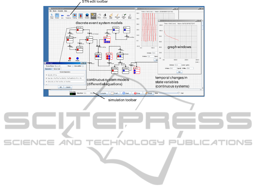
Figure 2: STN GUI simulator.
the actors in input scenes transit to output scenes, and
they write transit rules for the state variables.
2.4 Related Methods
This section describes related modeling and simu-
lation methods for discrete event systems and hy-
brid systems. Petri nets(Murata, 1989) are popular
methods to model and simulate discrete event sys-
tems. However, it is difficult to model and to sim-
ulate changes in continuous values. Fishwic have
proposed a modeling approach for hybrid systems by
combining different types of multiple modeling meth-
ods(Fishwick, 1991). However, it is difficult for this
approach to model and simulate behaviors of multiple
sub-systems, which operate concurrently, influencing
each other. Arena(W. D. Kelton and Sturrock, 2003)
is also a very useful software tool for discrete event
systems. This tool can be used as a simulation tool
for discrete-continuous hybrid systems, However, it is
not easy for designers to build hybrid models because
this tool is not designed on the premise of hybrid sys-
tem simulation.
3 STN GRAPHICAL USER
INTERFACE (GUI) SIMULATOR
The present authors have developed an STN GUI
(Graphical User Interface) simulator so that design-
ers can easily edit and simulate STN models. Fig-
ure 2 shows an overview of the GUI simulator. This
simulator consists of an STN edit toolbar, workspace,
simulation toolbar, and graph windows. In simulation
phases, it displays multiple graphs which show dy-
namical changes in designated actors’ state variables.
The designers analyze the behaviors of continuous
variable systems by observing these graphs. In addi-
tion, it also displays animation that shows the transi-
tions of the actors and they also analyze the behaviors
of the actors as discrete event systems. The details of
these components are described in (Tateyama et al., ).
4 MULTI-ASPECT MODELING
USING STN
Many large-scale industrial systems such as manufac-
turing systems include multiple subsystems that are
constructed for different purposes and different as-
pects. In addition, they include layered and parallel
structures that operate concurrently, influencing each
other. For verifying the behavior of such complex
systems in simulations, it is necessary to construct
multiple models of the sub-systems, integrate them by
taking into account the relationships among the sub-
systems and simulate them in parallel. For example,
the model of an automated transportation system in
a factory can be divided into the following three dif-
ferent submodels: (1) a dynamics model of an auto-
mated guided vehicle (AGV), (2) a decision-making
model of the AGV (for planning the navigation of
the AGV in a factory-like environment), and (3) a
model of transportation sequences of the product and
its parts. To verify the behavior of this system us-
ing STNs, it is important to construct three sub-STN
models through a thinking process called ”envision-
ing(de. Kleer, 1977)” and conduct simulations in par-
allel. Kawata et al. call this concept gmulti-aspect
modelingh using STNs(Kawada et al., 1996). In this
SCENE TRANSITION NETS SIMULATOR FOR MULTI-ASPECT MODELING OF DISCRETE-CONTINUOUS
HYBRID SYSTEMS
469
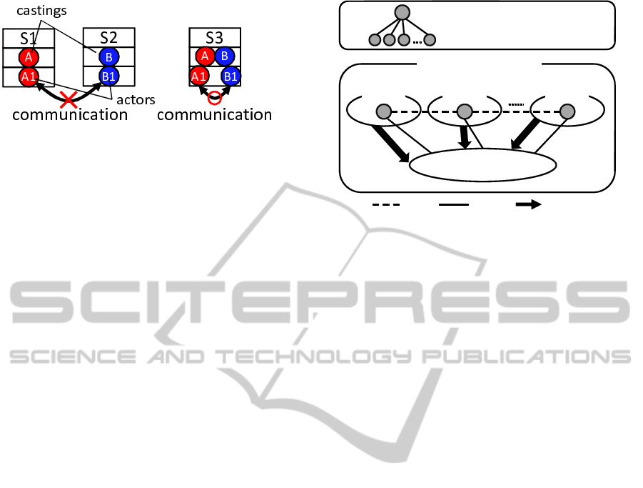
Figure 3: Possibility of communication between actors.
modeling method, as multiple independent STN mod-
els are constructed, the same actor is necessarily in-
cluded in multiple submodels(Kawada et al., 1996).
In the abovementioned example, the same AGV is in-
cluded in the three submodels (1), (2), and (3). The
behavior of an actor in a submodel influences behav-
ior of the actors in other submodels. Therefore, it is
necessary to create models of interactions among sub-
models for effective multi-aspect modeling. However,
an actor can be present only in one scene at a time and
cannot communicate with other actors (as shown in
Fig.3) in the basic STN concept. These shortcomings
make the interaction of sub-STN models with other
models difficult.
In this section, the authors resolve this shortcom-
ing by enabling the sharing of the state variables of
actors. This concept is called ”actor-link”. The fol-
lowing subsections describe this concept in detail and
show that this simple concept enables us to construct
layered and parallel structures of STNs and to per-
form multi-aspect modeling.
4.1 Actor-link
Figure 4 shows the concept of actor-links for shar-
ing the state variables of actors. In this concept, ac-
tors that are instances of the same actor class share
their state variables. Figure 4 shows that actors
A
1
,A
2
,...,A
n
, which are instances of actor A, share
their state variables x,y,z,.... Each shared state vari-
able is incremented according to multiple differential
equations (continuous system models) written in mul-
tiple scenes at every simulation time step. Therefore,
the variation in x is expressed by the following for-
mula.
∆x(t) =
N
∑
i=1
∆x
i
(t) (1)
Here, ∆x(t) is the variation in the state variable x at
time t. ∆x
i
(t) is the variation in x in the submodel i.
This concept realizes parallel simulation of mul-
tiple sub-STN models by considering the interactions
among them. The authors have implemented this con-
cept in the STN GUI simulator. Figure 12 shows a set-
sub-STN
model 1
shared state variables
actor class A
A
actors (instances of actor class A)
A
1
A
1
A
2
A
3
A
N
A
2
A
N
x, y, z, …
link share update
STN model
sub-STN
model 2
sub-STN
model N
Figure 4: Concept of actor-links.
ting window of the actor-links. This figure indicates
that actors ”AGV1,” ”AGV2,” ”AGV3,” and ”AGV4”
share their state variables. With this interface, users
can easily use the function of actor-links.
4.2 STN Modeling of Layered
Structures and Parallel Structures
using Actor-link Concepts
The actor-link concept enables us to construct lay-
ered and parallel structures of STNs and realize multi-
aspect modeling. Details of the manner in which lay-
ered and parallel structures are constructed are given
below.
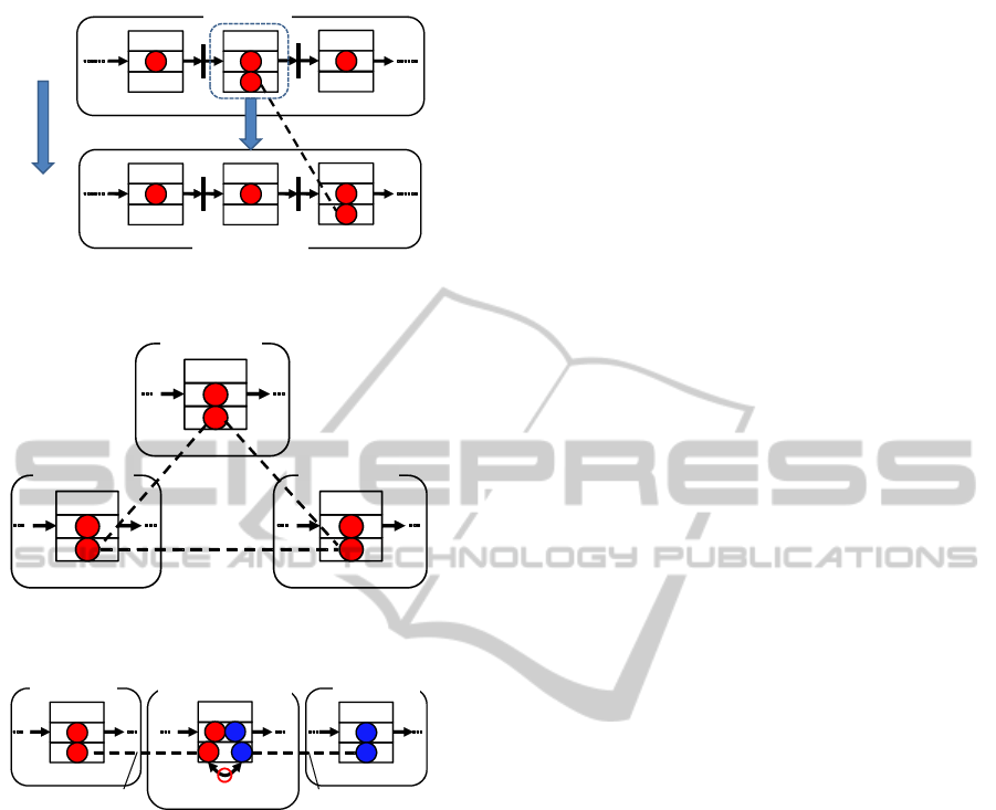
4.2.1 Layered Structure Modeling
Figure 5 shows a two-layered structure of an STN
model. Submodel 1 is an upper model, and submodel
2 is a lower model. This figure shows that submodel
2 is a detailed model of scene S1-2 in sub model 1. In
this model, actor A1 in submodel 1 and actor A2 in
submodel 2 are made equal by using actor-link con-
cepts. For example, in the modeling of manufacturing
systems, an upper model is a rough process sequence
and a lower model includes detailed processes in the
sequence. This multi-aspect modeling is based on two
aspects (a rough process sequence and a detailed pro-
cess).
4.2.2 Parallel Structure Modeling
Figure 6 shows a parallel structure in which three sub-
models run in parallel and interact with each other. In
this model, actors A1, A2, and A3 in submodels 1, 2,
and 3, respectively are considered to be equal. All the
state variables of the three actors are updated accord-
ing to the differential equations written in all the three
submodels. For example, a parallel process system
ICINCO 2011 - 8th International Conference on Informatics in Control, Automation and Robotics
470
S2-2
A
submodel 2
actor-link ( A1 = A2 )
S1-2
A1
A
submodel 1
S1-1
A
S1-3
A
detailed model of S1-2
S2-3
A2
A
S2-1
A
upper
model
lower
model
Figure 5: Layered structure modeling using actor-link con-
cepts.
S1-x
A1
A
submodel 1
Actor-link
( A1 = A2 = A3 )
S2-y
A2
A
submodel 2
S3-z
A3
A
submodel 3
Figure 6: Parallel structure modeling using actor-link con-
cepts.
S1-x
A1
A
S2-z
B1
B
S3-y
B2
A
A2
B
communication
submodel 1 submodel 2
submodel 3
( communication model )
actor-link
( A1 = A2 )
actor-link
( B1 = B2 )
Figure 7: Modeling of communication between two differ-
ent actors.
which processes in parallel parts by using three types
of process machines.
4.2.3 Modeling of Communication among
Different Actors
Different actors in different submodels can commu-
nicate by using actor-link concepts. In Fig.7, actors
A1 and B1 communicate through the communication
model (submodel 3) because actors A1 and A2, and
B1 and B2 are considered equal. For example, it
is possible to simulate autonomous distributed con-
trols of AGVs that wirelessly communicate with each
other.
It may possible to construct STN models of highly
complex systems by combining the abovementioned
structures.
5 AN EXAMPLE: AN
AUTOMATED
TRANSPORTATION SYSTEM
USING A BATTERY-POWERED
AGV
5.1 An Automated Transportation
System using a Battery-powered
AGV
This section describes an example of the modeling
and simulation of an automated transportation system
with a battery-powered AGV (automated guided vehi-
cle). Figure 8 shows the outline of the example. The
purpose of this system is to produce the products that
consist of parts A, processed by a process machin-
ery, and parts B. The AGV carries parts A from buffer
1 to the process machinery using a battery-powered
AGV. The AGV moves between buffer 1 and the pro-
cess machinery (distance: 50[m]) and between buffer
1 and the battery changer(distance: 10[m]). The AGV
can carry only one set of parts A at a time. After the
AGV throws parts A in the process machinery, it re-
turns to buffer 1. When the AGV reaches buffer 1,
it checks its battery voltage. If the voltage is higher
than V
th
, it continues to carry other parts; otherwise,
it goes to the battery changer in order to replace its
battery. The authors define the dynamics of the AGV
and the voltage of the batteries as follows:
˙x
˙
ω
˙
V
a
=
0 ±R 0
0 −ψ
2
/R
a
J ψ/R
a
J
0 aψ/R
a
−a/R
a
x
ω
V
a
+
0
−T l/J − R
c
0
(2)
Here, x(−10 ≤ x ≤ 50)[m] is the current position of
the AGV, ω [rad/sec] is the angular velocity of the
AGVfs motor, V
a
[V] is the current voltage of the
battery, R is the final reduction ratio, R
a
[Ω] is the
armature circuit resistance, J[kgm] is the total mo-
ment of inertia of the rotational system, ψ[Nm/A] is
the torque constant of the armature, Tl[Nm] is the
counter torque supplied to the motor shaft, R
c
[Ns/m]
is the viscous frictional drag, and a[V/As] is the char-
acteristic constant of the battery. The initial value of
V
a
is 100[V] and V
th
is 40[V]. The purpose of this sim-
ulation is to observe the AGVfs behavior, changes in
the battery voltage and efficiency of transportation of
the parts.
SCENE TRANSITION NETS SIMULATOR FOR MULTI-ASPECT MODELING OF DISCRETE-CONTINUOUS
HYBRID SYSTEMS
471

Figure 8: An automated transportation system using a battery-powered AGV.
Figure 9: An STN model constructed from a single aspect.
5.2 STN Modeling from a Single Aspect
Figure 9 shows an STN model constructed from a sin-
gle aspect using our old version simulator. This model
illustrates the whole transportation system by using a
single network. However, this modeling method has
some shortcomings. It includes several models con-
structed from different aspects such as models of the
AGV dynamics, temporal changes in the battery volt-
age, procedure of change of battery, and transporta-
tion routes. When we construct a complex system
model using a single STN, the procedure of modeling
also becomes complex. For example, we have to write
the AGV dynamics and battery voltage model for all
the scenes where the AGV functions. Specifically, we
have to write equations (2) for four scenes (routes T-1,
T-2, B-1, and B-2). It also requires time and effort to
rewrite them when we change the specifications of the
system. This example is relatively simple. However,
when system designers want to simulate a large-scale
and complex system model, it is difficult for them to
express it by using a single network and to observe its
behavior.
5.3 Multi-aspect STN Modeling and
Simulation
In this section, we have tried to construct the follow-
ing four simple sub-STN models and integrate them
for a concurrent and hierarchic simulation: (1) an
AGV dynamics model, (2) an AGV state model, (3) a
transportation process model and (4) a battery change
process model. The following subsections describe
the details of these submodels.
5.3.1 An AGV Dynamics Model
An AGV dynamics model is a very simple model,
which consists of only two scenes and an actor.
The actor is the AGV, which has ten state variables
(x,ω,V
a
,R, R
a
,J, ψ, T l,R
c
,a). The AGV actor tran-
sits to either ”stop” or ”run”. The two transitions in
ICINCO 2011 - 8th International Conference on Informatics in Control, Automation and Robotics
472

Figure 10: AGV dynamics model.
this model fire depending on the actors’ behaviors in
other models. We write the AGV’s dynamics only for
its motors and battery voltage in the scene ”run” as
shown in Fig.10, in order to temporally change the
values of its state variables during its motion. We
need not write the AGV’s dynamics in other models.
5.3.2 An AGV State Model
An AGV state model, shown in Fig.11 consists
of three scenes (”wait”, ”transport” and ”battery
change”) and an AGV actor. The scene ”wait” is a
scene in which the AGV is waiting for the parts A
to arrive at buffer 1. However, this model need not
include the actors of parts A and the buffer model.
We only write the AGV’s simple decision rules in the
scene ”wait” based on the current battery voltage of
the AGV.
5.3.3 A Transportation Process Model
This is a detailed model of the process of transporta-
tion, manufacturing, and assembly of parts A and B.
This model corresponds to the right side of the sin-
gle aspect model shown in Fig.9. The AGV transits
depending on its position x which temporally changes
according to the dynamics written in the AGV dynam-
ics model. For example, the transition between scene
Figure 11: AGV state model.
Figure 12: Actor-link setting window.
”route T-1” and ”process machinery” fires when the
value of x becomes 50[m].
5.3.4 A Battery Change Process Model
This is a detailed model of the routes between buffer
1 and the battery station. This model corresponds to
the left side of the single aspect model. We write cer-
tain firing conditions for transitions with respect to
the distance between buffer 1 and the battery station.
This model also need not consider other dynamics and
rules, like the transportation process model.
5.3.5 Actor-links and Multi-aspect Simulation
Finally, we define the links of the actors in order to
perform parallel simulation of the four STN models.
The STN GUI simulator makes it easy to define them.
Figure 12 is the user interface of the simulator for set-
ting the links. It shows that the four AGV actors in the
four STN models are regarded as same and they share
their state variables. The concept of actor-links re-
alizes the parallel simulation of the sub-STN models
considering their interactions, without making direct
connections between them using arcs and transitions.
5.4 Simulation and Results
We set ten sets each of parts A in the scene ”input”
and parts B in the scene ”buffer 2” and conduct par-
allel simulation. First, we observe the simulation re-
sult from the viewpoint of discrete-event systems. All
AGV actors are appropriately linked to each other
and move normally in the submodels. For example,
when the AGV stay in the scene ”route T-1” (it is
moving from buffer 1 to the process machinery) in
the transportation process model, it is also present in
the scenes ”run” in the AGV dynamics model and
”transport” in the AGV state and battery change pro-
cess models. By contrast, when it stays in the scene
”change”, it is also present in the scenes ”stop” in
the dynamics model and ”battery change” in the AGV
state and transportation process models.
Next, we observe the temporal changes in the state
variables as continuous systems expressed by the dif-
ferential equations. Figures 13 and 14 show the tem-
SCENE TRANSITION NETS SIMULATOR FOR MULTI-ASPECT MODELING OF DISCRETE-CONTINUOUS
HYBRID SYSTEMS
473
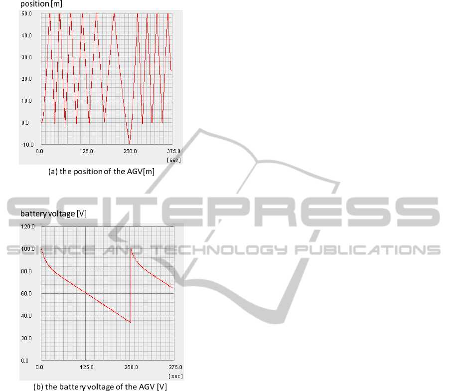
Figure 13: Temporal change of the position of the AGV
[m].
Figure 14: Temporal change of the battery voltage of the
AGV [V].
poral changes in the AGV’s position x and the bat-
tery voltage V
a
. These graphs show that the speed
of the AGV decreases according to the decrease in
the voltage of the battery. They also indicate that
the AGV goes to the battery station after the sixth
transportation of parts A and it changes the battery
at time t ≈ 250[s]. After changing the battery, the
speed of the AGV increases. In this way, we have con-
firmed that the proposed parallel simulation works ac-
curately, and this method enables us to observe the be-
haviors of the system from the viewpoint of discrete-
continuous hybrid systems.
6 DISCUSSION
In multi-aspect modeling, we first construct a few
simple sub-STN models and integrate them. This
modeling procedure is very effective for modeling
complex systems. We have confirmed that the di-
vision of a complex STN model using the concept
of multi-aspect modeling makes the working of STN
modeling easier through experiments. In addition,
the number of dynamics models we must write in
the STN model has also decreased. As a result, the
modeling method also simplifies the modification of
STN models. Multi-aspect modeling also contributes
to easy observation of the behaviors of complex sys-
tems. Each simple sub-STN model provides simple
and useful information to observers. The observers
easily obtain the necessary information by focusing
on appropriate submodels. For example, if an ob-
server wants to determine the AGV’s operating rate,
he obtains the required information by observing only
the behavior of the AGV dynamics model. On the
other hand, the AGV state model provides informa-
tion about the frequency of battery change. If an ob-
server wants to prove the efficiency of the transporta-
tion system, he should analyze the behavior of the
transportation process model. The concept of multi-
aspect modeling and the STN GUI simulator the au-
thors have developed will be more useful when we
verify more complex and larger-scale systems.
7 CONCLUSIONS
In this paper, the authors have proposed an STN mod-
eling concept called ”actor-link” that enables the shar-
ing the state variables of the actors. This simple con-
cept enables to construct complex layered and parallel
structures of STNs and perform multi-aspect model-
ing. The experiment with the case study of an auto-
mated transportation system using a battery-powered
AGV has shown that the proposed method and tool
assist users to easily construct multi-aspect models of
STNs and verify the behaviors of complex systems
from many different aspects.
ACKNOWLEDGEMENTS
This research was supported by Japan Productivity
Center, Grant-in-Aid for Productivity Research 2010.
ICINCO 2011 - 8th International Conference on Informatics in Control, Automation and Robotics
474

REFERENCES
de. Kleer, J. (1977). Multiple representations of knowledge
in a machanics problemsolver. Proceedings of 5th IJ-
CAI, pages 299–304.
Fishwick, P. A. (1991). Hetrogeneous decomposition and
inter-level coupling for combined modeling. Proceed-
ings of the 1991 Winter Simulation Conference, pages
1120–1128.
Kawada, S., Kawata, S., Kawai, S., Matsunaga, S., and
Watanabe, A. (1996). Some extensions of a scene
transition net by introducing actor transformation and
multi-aspect stn. Transactions of the Japan Soci-
ety of Mechanical Engineers, C62(599):2905–2912(in
Japanese).
Kawata, S., Kawada, S., and Watanabe, A. (1994a). The
discrete/continuous hybrid simulation using the scene
transition net. Proceedings of the First Asian Control
Conference(ASCC94), 1:567–570.
Kawata, S., Kawada, S., and Watanabe, A. (1994b). A man-
ufacturing system modeling using a scene transition
net. New Direction in Simulation for Manufacturing
and Communication, pages 86–92.
Murata, T. (1989). Petri nets: Properties, analysis and ap-
plication. Proceedings of the IEEE, 77(4):541–580.
Tateyama, T., Chin, T., Kawata, S., and Shimomura, Y.
Development and improvement of scene transition
nets(stn) gui simulator for discrete-continuous hybrid
systems. International Journal of CAD/CAM, 8(1).
Tateyama, T., Shimomura, Y., Mikoshiba, S., and Kawata,
S. (2010). Service flow simulator using scene tran-
sition nets (stn) including satisfaction-attribute value
functions. Proceedings of the 15th Design for Manu-
facturing and the Lifecycle Conference - DFMLC2010
-.
W. D. Kelton, R. P. S. and Sturrock, D. T. (2003). Simula-
tion with Arena. McGraw-Hill Science/Engineering.
SCENE TRANSITION NETS SIMULATOR FOR MULTI-ASPECT MODELING OF DISCRETE-CONTINUOUS
HYBRID SYSTEMS
475
