
COMPUTER AIDED CONCEPTUAL VISUAL DESIGN
BASED ON ONTOLOGY
Ewa Grabska
Faculty of Physics, Astronomy and Applied Computer Science, Jagiellonian University, 4 Reymont Str., Krakow, Poland
Keywords: Visual design, Design requirement, Diagram, Design knowledge, First order logic.
Abstract: This paper presents a broad range of ontological aspects that are related to conceptual visual design aided by
computer. A formal model of visual design system is defined. In the considered exemplary CAD system
based on the model, design ideas are visualized in the form of diagrams created by the designer on the
monitor screen. Designer’s diagrams are automatically transformed by the system into data structures. De-
sign knowledge encoded in the data structures is transformed into sentences of the first order logic. The ob-
tained logic language enables the system to reason about compatibility of designer’s solutions with specified
constraints.
1 INTRODUCTION
Computer Aided Design is well-established research
area. Contemporary CAD systems, following the
Building Information Modelling paradigm, store all
project’s 3D elements in a central database and are
able to generate 2D drawings and 3D renderings
(Eastman et al., 2008
). Although there are many
computational tools for describing, editing, analyz-
ing, and evaluating design projects
the application of
ontology in CAD is relatively new and problem
oriented (Yurchyshyna and Zarli, 2009). This is one
of the reason that the initial conceptual design phase,
mainly based on ontological knowledge, is very
rarely supported by computer. In conceptual design
process understanding of requirements goes together
with the visualization of early design solution
(Grabska, 2010). Visual thinking is supported by
cognitive tools, such as computer screen (Tversky
and Suwa, 2010). This paper considers a broad range
of ontological aspects that are related to conceptual
visual design aided by computer. The proposed top-
level ontology constitutes a framework for the study
of visual conceptual design process and is related to
a kind of conversation of designers with their draw-
ings on the monitor screen. On the basis of this on-
tology an exemplary of the computer-aided design
system supporting conceptual design is outlined.
2 FORMAL MODEL
During the conceptual visual design process aided
by computer the designer has a kind of conversation
with their diagrams. This dialogue can be characte-
rized as the following cycle: drawing diagrams, in-
specting them, finding new things (e.g., emergent
shapes and/or relations, feedback from the computer
system), and redrawing (Goldschmidt, 1994).
The proposed ontology of conceptual visual de-
sign aided by computer considers the dialogue in a
formal way. To describe this dialogue key concepts
are distinguished: a design task t, a visual site v, a
physical design action a, and a data structure s. Each
design task is classified by requirements which are
modified during the design process. A visual site is
constituted by a drawing of a design solution and a
surface (a cognitive tool) on which it is drawn. Two
different drawings on the same surface, e.g., on the
monitor screen, determine two different visual sites.
A physical design action is one of such operations as
drawing, copying and erasing visual elements.
The categorization of sets of key design concepts
is given by the notion of classification (Barwise and
Seligman, 1997).
Definition 1. A classification is a triple
D = (O,
Σ
O
, |−
O
), where:
• O – is a set of objects to be classified,
•
Σ
O
– is a set of types used to classify objects of O,
396
Grabska E..
COMPUTER AIDED CONCEPTUAL VISUAL DESIGN BASED ON ONTOLOGY.
DOI: 10.5220/0003652403960399
In Proceedings of the International Conference on Knowledge Engineering and Ontology Development (KEOD-2011), pages 396-399
ISBN: 978-989-8425-80-5
Copyright
c
2011 SCITEPRESS (Science and Technology Publications, Lda.)

• |−
O
– is a binary relation between O and
Σ
O
that
specifies which objects are classified as being of
which types.
Conceptual visual design is characterized by
three relations: a semantic convention =>, signalling
—›, and an input-output relation ~›. The first rela-
tion => is defined between constraints on visual sites
and constraints determined by designer’s require-
ments. The second one —› is based on visual per-
ception and determines visual sites used to find a
solution of design task (Shimojima, 1996). The third
relation ~› is a tertiary one and determines input
visual site and output visual site for a given action.
A formal model of Computer Aided Conceptual
Visual Design (CACVD) is defined as follows:
Definition 2. A CACVD system is a 5-tuple
C
= (D
T
, D
V
, D
A
, =>, —›, ~› ), where:
• D
T
= (T,
Σ
Τ
,
|
−
Τ
) is a classification of a set T of
design tasks,
• D
V
= (V
×
S,
Σ
V
∪
Σ
S
, |−
V
) is a classification of
visual sites, where V
×
S is a set of pairs (v, s),
Σ
V
is a set of types used to classify the visual sites V
and
Σ
S
is a set logic formula supporting the clas-
sification of the visual sites, on the basis of data
structures of S,
• D
A
= (A,
Σ
A
, |−A) is a classification of physical
design actions,
• => is a relation from
Σ
V
∪
Σ
S
to
Σ
T
, called a se-
mantic convention,
• —› is a binary relation from V to T called a sig-
nalling relation,
• ~› is a tertiary relation
Σ
V
x
Σ
x
Σ
V
called an in-
put-output relation, v
i
~›
a
v
o
means that action a
has v
i
as an input visual site and v
o
as an output
visual site.
Signalling relations —› together with semantic con-
vention => form a mapping from the set D
V
to the
set D
T
. This mapping defines the ontological com-
mitment between visual sites and design tasks.
For all actions a, a’ in A and visual sites v, v’ in
V the composition a • a’ is defined by means of an
extension relation ~› with the input visual site v and
with the output visual site v’ in the following way:
Definition 3. v ~›
a • a’
v’ iff there is a visual site v*
in D
V
such that v ~›
a
v* and v* ~›
a’
v’.
The CACVD system allows one to describe a
visual design process and manner in which the de-
signer thinks about design problems. There are two
major categories of thinking: divergent and conver-
gent (Lawson, 2001). Divergent thinking is imagina-
tive and intuitive, whereas the convergent one is
logical and rational. Taken as a whole, design is a
divergent task. However, during the process of crea-
tive design good designers are able to develop and
maintain several lines of thought, both convergent
and divergent.
The divergent task for designer’s mind is an
open-ended approach seeking alternative. In our
model the definition of divergence is as follows:
Definition 4. Let
C
= (D
T
, D
V
, D
A
, =>, —›, ~› ) be
a CACVD system and σ
1
,…, σ
n
be a sequence of
types classifying design tasks of T, and => be a se-
mantic convention. The model CACVD imposes
divergence on the types σ
1
,…, σ
n
iff there exists an
input visual site v
i
in V and a sequence of actions
a
1
,…, a
m
in A
such that:
• The types σ
1
,…, σ
n
allow the composition action
a
1
•…• a
m
on the visual site v
i
.
• The output visual site v
o
for the action a
1
•…•a
m
allows new types
ω
1
*,…,
ω
k
* in
Σ
V
for k > 1
such that v
o
|
−
V
ω
i
* for all
i = 1,…,k.
• On the semantic convention =>, each type
ω
i
*
confirm a type σ of
Σ
Τ
or/and can indicate a new
type of
Σ
Τ
.
In other words, the composition of actions a
1
,…, a
m
leads to the output visualization site which allows
the designer to discover new facts. Each of these fact
can inspire the designer to perform one of alternative
actions or to formulate a devised requirement. The
convergent way of thinking can be defined in an
analogical way.
3 CAD SYSTEM BASED ON
ONTOLOGY
Assumptions for a CAD system supporting concep-
tual visual design based on CACVD model are as
follows:
1. visualizations of early solutions are the main
source of knowledge about created designs,
2. these visualizations created by the designer on
the monitor screen are automatically trans-
formed into data structures,
3. the system transforms semantic and syntactic
information encoded in the data structure into
sentences of a logical language forming design
knowledge about early solutions,
4. a method of reasoning about compatibility of
design solutions with specified constraints is
developed.
Figure 1 shows relations between the designer with
CAD system and components of formal model. Po-
COMPUTER AIDED CONCEPTUAL VISUAL DESIGN BASED ON ONTOLOGY
397
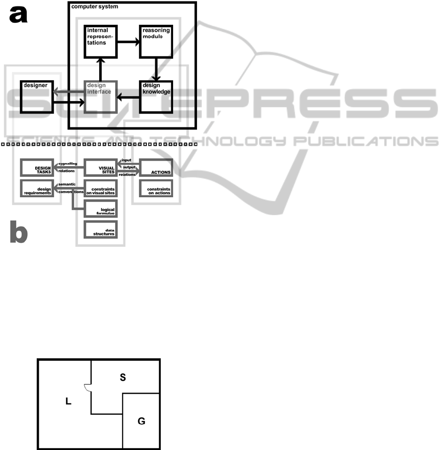
lygons with grey sides represent common areas. Let
us consider some components of an exemplary CAD
system based on the ontology which has been devel-
oped (Grabska E., et al., 2008). In this system design
ideas are visualized by means of diagrams. A spe-
cialized diagram language consists of a vocabulary
being a finite set of visual elements and a finite set
of rules specifying possible configurations of these
visual elements.
Figure 1: CAD system based on ontology: a) A schema of
conceptual visual design system; b) Key concepts and
relations of its formal model.
Let us consider a simplified specialized CAD
editor for designing floor layout composed of poly-
gons which are placed in an orthogonal grid. These
polygons represent functional areas or rooms. A
diagram with three component is shown in Figure 2.
Figure 2: The diagram with three components.
Mutual location of polygons is determined by the
designer. The sides of each polygon are ordered
clock-wise starting from the top left-most one. In a
diagram only qualitative coordinates are used i.e.,
only relations among graphical elements (walls) are
essential.
It is known that graphs are useful for specifica-
tion of knowledge. In the graph knowledge represen-
tation the way of organization, processing and ma-
nipulation of design knowledge is based on the spa-
tial relation between objects. Conceptual graphs
have been proposed as a knowledge representation
and reasoning model (Sowa, 1984). They have been
used as a graphical interface for logics. During con-
ceptual visual design process the designer often
modifies a design diagram and/or changes design
these changes
computer readable graph operations
and graph rules are defined. Therefore for modelling
and modification of knowledge about diagrams we
propose to use hyper-graphs which can be treated as
an extension of conceptual graphs with appropriate
structures for local graph transformations.
The proposed hyper-graphs have two types of
hyper-edges, called component hyper-edges and
relational hyper-edges. Hyper-edges of the first type
correspond to drawing components and are labeled
by component names. Hyper-edges of the second
type represent relations among fragments of compo-
nents and can be either directed or non-directed in
the case of symmetric relations. Relational hyper-
edges of the hyper-graph are labeled by names of
relations. Component hyper-edges are connected
with relational hyper-edges by means of nodes cor-
responding to common fragments of connected de-
sign components.
Definition 5. Let Σ be an alphabet of labels of hy-
per-edges and nodes. An hyper-graph over Σ is a
system
G = (E, V, t, s, lb, att, ext), where:
• E = E
C
∪
E
R
is a finite set of hyper-edges,
where elements of E
C
, called component hyper-
edges, represent drawing components, while
elements of E
R
, called relational hyper-edges,
represent relations,
• V is a nonempty finite set of nodes,
• t: E → V* is a mapping assigning sequences of
different target nodes to all hyper-edges,
• s : E
R
→ V* is a mapping assigning sequences
of different source nodes to relational hyper-
edges,
• lb: E ∪ V →Σ is a labeling function.
An example of the internal representation of the
diagram presented in Figure 2 is shown in Figure 3.
Drawing the diagram the designer specifies la-
bels of components related to room types. While he
KEOD 2011 - International Conference on Knowledge Engineering and Ontology Development
398

designer creates a diagram and/or modifies it using
design actions, the hyper-graph is automatically
generated.
For each labelled design component in the form of a
polygon one component hyper-edge is created.
Figure 3: The hyper-graph for the drawing in Fig. 2.
Semantic information about this component de-
scribing it as a room is automatically completed by a
hyper-edge label describing a type of this room.
When the designer divides a component into parts,
the hyper-graph composed of component and rela-
tional hyper-edges representing the arrangement of
these parts is nested in the component hyper-edge
representing the divided component. For each line
shared by polygons in the diagram one relational
hyper-edge connecting nodes representing corre-
sponding sides of the polygons is generated. Seman-
tic information about this relation depends on the
line styles and determines the type of the relational
hyper-edge label. In the considered example, lines
with door symbol on them represent the accessibility
relation among components, while continuous lines
shared by polygons denote the adjacency relations
between them.
During the conceptual visual design process
aided by computer diagrams created by the designer
and transformed to appropriate hyper-graphs and
then translated to sentences of the first-order logic.
In this process a problem-oriented relational struc-
ture, which assigns elements of hyper-graphs to enti-
ties of the specified first-order logic alphabet is used.
The design domain of this structure includes: a set of
component hyper-edges, and a set of hyper-graph
nodes. Relations between design components pre-
sented in the diagram are specified between frag-
ments of these components, which correspond to
hyper-graph nodes. The interpretation of each rela-
tion is the hyper-edge relation of the hyper-graph
such that there is a relational hyper-edge coming
from a sequence of nodes of at least one component
hyper-edge and coming into a sequence of nodes of
other component hyper-edges.
4 CONCLUSIONS
This paper is an attempt to present a formal coherent
framework for computer aided conceptual visual
design aided by computer. Important features of this
framework are as follows:
• a distinction between different kinds of knowl-
edge determined by designer’s requirements,
visual sites, actions, data structures and logical
languages,
• a formal description of divergent and conver-
gent categories of thinking,
• a formal description of the fundamentals of vis-
ual design necessary to devise CAD-systems
and new computer cognitive tools.
REFERENCES
Eastman, Ch., et al. 2008. BIM Handbook: A Guide to
Building Information Modeling for Owners, Manag-
ers, Designers, Engineers and Contractors, Wiley.
Yurchyshyna, A., Zarli, A., 2009. An Ontology-based
Approach for Formalisation and Semantic Organiza-
tion of Conformance Requirements in Construction.
International Research Journal Automation in Con-
struction. Volume 18. Issue 8. pp. 1084-1098.
Grabska, E., 2010. Visual design with the use of graph-
based data structure. eWork and e business in Archi-
tecture, Engineering and Construction. Mentzel and
Schere (Eds). Taylor and Francis Group. London, pp.
209-214.
Tversky, B., Suwa, M. (2009). Thinking with sketches.
Markman, A. B. & Wood, K. L., (Eds.), Tools for innova-
tion, Oxford.
Guarino, N., et al. 2009. What Is an Ontology. Handbook
on Ontologies. Springer, Heildelberg.
Ware, C., 2008. Visual thinking for design, Elsevier.
Goldschmidt, G., 1994. On visual design thinking. Design
Studies 15, pp.158-174.
Barwise J., Seligman J., 1997. The Logic of Distributed
Systems, Cambridge University Press.
Shimojima A., 1996. Operational Constraints in Dia-
grammatic Reasoning. Logical Reasoning with Dia-
grams. Oxford University Press, pp. 27-48.
Lawson B., 2001. How designers think: the design process
demystified. Butterworth Architecture. Oxford.
Grabska, E., et al. 2008. Visual Design and Reasoning
with the Use of Hypergraph Transformations.
ECEASST 10, pp. 1-15.
Sowa, J. F. 1984. Conceptual Structures: Information
Processing in Mind and Machine. Addison-Wesley.
COMPUTER AIDED CONCEPTUAL VISUAL DESIGN BASED ON ONTOLOGY
399
