
A FUZZY LOGIC APPROACH USED IN THE INVERSE
KINEMATIC ALGORITHM OF A SPACE ZERO-G FREE
FLYING ROBOT
Andrea Bulgarelli
1
, Alessio Aboudan
2
, Carlo Menon
3
, Massimo Trifoglio
1
and Fulvio Gianotti
1
1
Institute for Space Astrophysics and Cosmic Physics (IASF) Bologna, INAF, Via Gobetti 101, 40129 Bologna, Italy
2
CISAS “G. Colombo”, University of Padova, Via Venezia 15, 35131 Padova, Italy
3
Menrva Group, School of Engineering Science, Simon Fraser University
8888 University Dr., Burnaby, BC, V5A 1S6, Canada
Keywords: Redundant space robot manipulator, Inverse kinematic control, Hierarchical fuzzy system controller, Fixed
attitude restricted motion problem.
Abstract: A fuzzy algorithm for the fixed attitude restricted motion problem of free-flying robots is proposed in this
paper. One of the main applications is to guide the robotic arm of a space servicing satellite: in such a
mission, one of the priorities is to reduce disturbances on the satellite attitude induced by robotic arm
movements so as not to perturb the pointing position of the satellite. A robot whose base has both mass and
inertia of the same order of magnitude of its robotic arm is considered - in this configuration the disturbance
of the satellite attitude is not negligible. Objective is to plan the robot’s arm motion in such a way as the
end-effector tracks a desired trajectory while disturbances on the base’s attitude are minimized. This
objective is achieved by taking into account the coupling between the arm and the floating base of the robot
in the kinematic inversion of the guiding control, controlling the gain matrix of the subtask introduced in the
kinematic inversion equation by means of a fuzzy algorithm. The proposed strategy combines the
advantages of the inverse kinematic algorithm and a fuzzy logic approach.
1 INTRODUCTION
The advancement of space robotics is currently
recognized by space agencies as a key strategy to
reduce costs of space exploration. Robotic systems
can advantageously be used during robotic
exploration missions, on-orbit servicing operations
Internal Vehicular Activities (IVA) and Extra-
Vehicular Activities (EVA) substituting astronauts
during operations. The use of a floating robot with a
dexterous arm is considered to be a viable option for
on-orbit servicing (Hirzinger, 2000; Tatsch, 2006;
Thronson, 2008).
Hence, controlling autonomous robotic systems
is of outmost importance and research is currently
focusing on the development of algorithms, which
allow performing safe and complex robotic
manoeuvres in space. Many space agencies have
funded important programs for developing space
robotic systems (Hirzinger, 1994; Yoshida, 2003;
Roderick, 2004; Marzwell, 2001; Culbertson, 2003;
Oda, 2008).
In this paper, we tackle the problem of controlling a
platform to be used in space servicing missions. In
the framework of this research, a spacecraft
equipped with a robotic arm is considered to be a
free-flying robot where the spacecraft is the floating
base of the robot - no active thrusters are considered
in this study. The goal is to plan the robot’s arm
motion in such a way that the end-effector tracks a
desired trajectory while disturbances on the base’s
attitude are minimized. This problem is known as
Fixed Attitude Restricted (FAR) motion problem
(Gu, 1993; Sagara, 2008; Boning, 2010,
Khaloozadeh, 2010; Rastegaria, 2010). We
investigated the problem in which both mass and
inertia of the base are comparable to those of the
robotic arm - the disturbance produced by the arm
on the base can therefore be significant if a non-
suitable controller is used. The goal is achieved by
taking into account the coupling between the arm
and the base of the robot in the kinematic inversion
of the guiding control and by combining the
advantages of inverse kinematic algorithms and a
429
Bulgarelli A., Aboudan A., Menon C., Trifoglio M. and Gianotti F..
A FUZZY LOGIC APPROACH USED IN THE INVERSE KINEMATIC ALGORITHM OF A SPACE ZERO-G FREE FLYING ROBOT.
DOI: 10.5220/0003653304290434
In Proceedings of the International Conference on Evolutionary Computation Theory and Applications (FCTA-2011), pages 429-434
ISBN: 978-989-8425-83-6
Copyright
c
2011 SCITEPRESS (Science and Technology Publications, Lda.)

Fuzzy Logic approach.
This work follows an experimental phase in
which our working group has built a free-floating
robot that was tested during the Sixth Student
Parabolic Flight Campaign sponsored by the ESA
(Menon, 2003; Menon, 2004; Cocuzza, 2004;
Menon, 2005).
In Section 2 we introduce the fixed attitude
restricted motion problem. In Section 3 the fuzzy
algorithm is presented. Section 4 reports the
simulation performed to test the algorithm and the
main results. Finally, Section 5 draws the conclusion
of this work.
2 KINEMATIC CONTROL
The free-floating problem (FFP), which we
considered, consists in the description and control of
a system in which (i) the position and orientation of
the spacecraft respect to an inertial coordinate
system are well-known in the initial state, (ii) there
are no external forces or torques about the center of
mass, hence the conservation of momentum and the
equilibrium of forces and moments hold strictly true,
(iii) there are no attitude control devices such as
reaction wheels or thrusters - internal forces are
generated only by joint motors, (iv) the robot acts in
a zero-gravity environment. In order to solve the
FFP, the linear and angular momentum conservation
laws are used. The considered system is
nonholonomic, namely the satellite orientation is not
only a function of the joint configuration, but also a
function of the path taken to reach such an
orientation. As a consequence, nonholonomy offers
the possibility to perform a reorientation of the
satellite using the motion of the only robotic arm
(Nenchev, 1988; Nenchev, 1992). This could be
useful in docking operations to save fuel and reduce
pollution near the target satellite. This kind of
manoeuvres can be employed to augment the
workspace of the robot too; it allows turning the
satellite into a different orientation, bringing back
the manipulator into its reference configuration.
Another possibility resulting from nonholonomy is
that manoeuvres can be sought to reduce attitude
variation of the spacecraft.
A closed loop differential kinematic inversion
algorithm can be adopted (Sciavicco, 1988;
Nenchev, 1992; Siciliano, 1993) and additional
subtasks introduced. In out context, n is the number
of degrees of freedom of our problem, m
a
is the
dimension of operating space of the arm and m
b
is
the dimension of operating space of the base or
spacecraft; for a 3D environment, m
b
=6. If
a
q
is the
velocity vector of the arm joints, it is represented by
the following equation:
()( ) ( )
T
aAG p d AGAGccc
qJqKex IJJJKe
++
=++−
(1)
where q is the vector of joint positions (arm and
base), J
AG
is the Analytic Generalized Jacobian
(Umetani, 1989; Menon, 2003),
J
A
G
+
is its pseudo-
inverse, e is error of the end-effector (the difference
between desired and real position), x
d
is the desired
position and orientation of working space, K
p
and K
c
are gain matrixes (K
c
is positive definite), I is the
identity matrix, J
c
is the Jacobian associated to the
constraint task error, e
c
is the error of the constraint
task defined as e
c
=q
bd
–q
b
where q
b
is a generalized
position variable of the free floating base of the
robot that is constrained to the desired trajectory q
bd
.
The matrix
(I
−
J
AG
+
J
AG
)
projects the joint velocity
contribution into the null space of the generalized
Jacobian in order to separate the constraint and end-
effector tasks.
Since the aim is to keep fix a rotational angle of
the base, the constraint error can be expressed as
e
c
=-q
b
. In order to obtain high performance of this
algorithm, K
c
should be selected properly (Menon,
2005): the variables of interest should be handled in
a flexible manner for planning optimal trajectories
while taking into account the constraints of the
problem; a fuzzy algorithm capable to online adjust
the elements of the K
c
matrix, and therefore manage
the motion of the robot is implemented.
In an experiment performed with a free-floating
robot that was tested during the Sixth Student
Parabolic Flight Campaign sponsored by the ESA
(Menon, 2003; Menon, 2004; Cocuzza, 2004;
Menon, 2005) we have proved the real possibility of
keeping the robot base stationary during arm
operations with a K
c
matrix fixed. This work is an
improvement of the experimental results: the main
purpose of the proposed solution is to handle the K
c
matrix during the trajectory evolution and controls
any instability that can be induced to the system.
Specifically, a Mamdami Fuzzy Inference System
(FIS) is developed to control the values of K
c
during
the evolution of the trajectory of the space robot.
The use of fuzzy systems has been extensively used
in other works e.g. (Gu, 1993; Antonelli, 2003;
Radaideh, 2003; De Santis, 2008; Zou, 2009; Fu,
2009) - in this work we have used this approach to
control the motion of a free-floating robot operating
in a zero-g environment.
The representation of the robot is obtained by
using the reference frame proposed in Menon
FCTA 2011 - International Conference on Fuzzy Computation Theory and Applications
430

(2005): the entire system is modelled as a single
robot with a fixed base. To describe the position and
orientation of the base, a fictitious arm, which is a
sequence of frames and joints linking the inertial
reference frame to the base itself, is introduced.
Because the free-floating base has six degree of
freedoms (DOF), we considered a fictitious arm with
three prismatic and three revolute joints, called
virtual joints.
3 FUZZY LOGIC ALGORITHM
The correct determination of the K
c
matrix of Eq.1 is
of fundamental importance to effectively solve the
constraint minimization problem for the following
reasons: (1) an unstable dynamic response of the
robotic system and an increased position error of the
end-effector could be caused by selecting too large
values of the elements of the K
c
matrix; (2) imposed
constrains could not be satisfied if elements of the K
c
matrix assume too small values.
The proposed fuzzy algorithm selects the
elements of the K
c
matrix in order to minimize the
error e
c
(see Eq.1). This algorithm combines the
advantages of the inverse kinematic algorithm (see
Section 2) with a Fuzzy Logic approach with a
hierarchical structure having a conventional
differential inverse kinematic algorithm at the
bottom layer (Eq.1) and a tuner at an upper-level: at
each step the kinematic is inverted using the K
c
matrix calculated by fuzzy algorithm in the previous
step. This work is related to the top-level tuner using
a fuzzy approach: this tuner uses a set of linguistic
rules for adjusting the constraint error gain matrix
during the kinematic inversion. The performance of
this fuzzy tuner is evaluated hereafter on the basis of
simulation results. The proposed algorithm takes as
input the constraint error e
c
=-q
b
defined in Section 2.
3.1 Detection of Oscillations
Possible dynamic oscillations of the robotic system
are detected by monitoring the oscillation of the
joint velocity
q
; at this purpose a moving average
filter is used.
During the calculation of the differential inverse
kinematics, for each time step the moving average of
the joint velocity vector is calculated, and compared
with its actual value. If the moving average is
crossed twice by the joint velocity the joint velocity
q
is determined to be oscillating. The number of
joints (for the arm) and virtual joints (for the base),
which are oscillating, becomes an input of the fuzzy
algorithm.
The crisp inputs of the FIS are the constraint
error e
c
and the number of oscillating joints. The
crisp output is the increment or the decrement of the
current K
c
elements.
Two linguistic variable are considered:
constraint error = {zero (Z), positive small (PS),
positive (P), positive medium (PM), positive large
(PL)} and oscillation = {OFF, ON}, where OFF
means no oscillations. If the constraint error is
greater than 0.1 rad/s, the error is considered PL.
The output linguistic variable is the gain increment =
{Negative Large (NL), Negative (N), Zero (Z),
Positive Small (PS), Positive (P), Positive Large
(PL)} that is the increments of K
c
elements; the
fuzzy sets used for this output linguistic variable are
not symmetric. In fact, for a better management of
the instability for a more rapid decrement of the K
c
the robotic system can react in a better way to the
system instability that can be reached during the
increment of the Kc.
The membership functions used for the input and
output linguistic variable are reported in Fig. 1.
The fuzzy rules used are the follows: (1) if
(constraint error is Zero) or (constraint error is
Positive Small) and (oscillation is OFF then (gain
increment is Positive Small); (2) if (constraint error
is Positive) and (oscillation is OFF) then (gain
increment is Positive); (3) if (constraint error is
Positive Large) and (oscillation is OFF) then (gain
increment is Positive Large); (4) if (oscillation is
ON) then (gain increment is Negative Large).
The main idea of the algorithm is the following:
if the system has no oscillations, the increment of
gain matrix is in the same direction of the constraint
error: this enable the controller to increment the
weight of the constraint that we have added to
resolve the FAR motion problem, but when the
instability is reached the controller reacts and
decrements rapidly the gain matrix.
4 SIMULATIONS
The test bed for the evaluation and comparison of
the algorithm presented in this paper is based on a
Matlab simulator developed by the authors. This
simulator enables the simulation of (i) rigid body
motion, (ii) direct and inverse kinematic (iii)
differential kinematic, and (iv) control problem. It is
possible to build various types of redundant or non-
redundant robots with fixed or free-floating base and
with revolute or prismatic joints.
A FUZZY LOGIC APPROACH USED IN THE INVERSE KINEMATIC ALGORITHM OF A SPACE ZERO-G FREE
FLYING ROBOT
431

Figure 1: Fuzzy membership input and output functions.
From left to right: (a) constraint error; (b) oscillation of
joints; (c) output K
c
.
The geometrical parameters of the robot, which were
selected for the simulation, were those of a robotic
prototype tested by the authors during the Sixth
Student ESA Parabolic Flight Campaign. This
prototype was a free-floating robot with 4 DOFs
operating in a 3D zero-g space environment. Table 1
reports the links of the parameters of the simulated
robot.
For all links the mass is 4 kg. The mass of the
base is 16 kg and its inertia is:
I
b
=
0.5760 0 0
0 0.5760 0
0 0 0.5760
⎛
⎝
⎜
⎜
⎜
⎞
⎠
⎟
⎟
⎟
kg m
2
(3)
With a 4-DOF robotic arm, it is possible to control
the position or orientation of the end-effector and
keep fixed the rotation of the base about one axis:
this means that the K
c
becomes a scalar. The end-
effector (EE) position and the yaw angle of the base
were chosen as desired parameters to be controlled
in this study.
Table 1: Parameters of the simulated robot.
Link
Arm
length
Arm center
of mass
Inertia tensor
7, 8, 9 1 m 0.5 m
0.3358 0 0
0 0.3358 0
0 0 0.0450
⎛
⎝
⎜
⎜
⎜
⎞
⎠
⎟
⎟
⎟
kgm
2
10 0.5 m 0.25 m
0.1892 0 0
0 0.0450 0
0 0 0.1892
⎛
⎝
⎜
⎜
⎜
⎞
⎠
⎟
⎟
⎟
kgm
2
About 1000 random trajectories of the EE were
used as input for the kinematic inversion algorithms.
To test if the generated trajectories were physically
consistent, the calculated trajectories were passed to
the robot simulator with a robust control algorithm
that control the end-effector position and the yaw
angle of the base (Menon, 2005) and compared with
the desired input. The fuzzy algorithm uses the same
robust controller but it adapts the K
c
matrix. A max
rotation of 0.4 rad in 10-15 s (the last of simulated
trajectories) is considered for the base yaw angle.
The integration step time is 0.01 s.
The following parameters were considered to
evaluate the performance of the algorithm and
reported in Table 2: (i) EE pos.: norm of the end-
effector position error (difference between the
desired and generated trajectory), (ii) maximum
(Max d.) and mean deviation (Mean d.) of the base
yaw angle with respect to a zero rotation, (iii)
Oscill.: mean value of the oscillation occurring
during the kinematic inversion (this was considered
to be a suitable parameter to evaluate the stability),
that is the number of joints that oscillate for each
step time divided for the number of steps.
Table 2 reports the main results of the performed
simulations with the proposed fuzzy algorithms with
respect to the approach of Eq. 1 (called classical
approach in this context) with a fixed K
c
, where the
first column reports the K
c
value used as a constant
(for the closed loop inverse algorithm) or the starting
K
c
value for the fuzzy algorithm.
From Table 2 it is possible to note that the mean
and maximum deviation from the zero trajectory of
the base yaw angle is smaller than the classical
approach; in addition, the number of oscillations of
the fuzzy algorithm is comparable to the one
obtained with a classical approach, with the
exception of cases with initial K
c
≥1000, in which the
algorithm acts as a system stabilizer. This is a very
interesting behaviour and an important result of this
algorithm; in fact the algorithm is able to reduce or
eliminate large joint oscillations by increasing K
c
,
enabling the optimization of the fixed attitude
restricted motion subtask; this behaviour provides
justification of the smaller end-effector position
error obtained by using the fuzzy algorithm.
Some examples of trajectories are shown on the
left–hand side of Fig. 3, 4 and 5. Each Figure
contains a trajectory with (i) orientation of the yaw
angle of the base not constrained, (ii) orientation
constrained with K
c
=1000
fixed (Eq.1), (iii)
orientation of the proposed fuzzy algorithm; the
right panel shows the K
c
value selected by the fuzzy
algorithm. Fig. 3 reports an example of trajectory in
FCTA 2011 - International Conference on Fuzzy Computation Theory and Applications
432
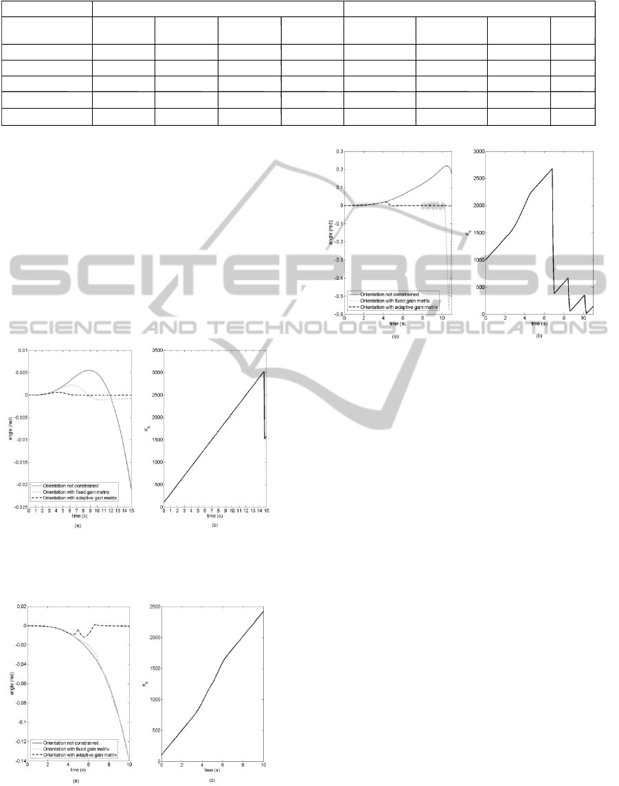
Table 2: Comparison between closed loop algorithm with fixed and fuzzy-adaptive K
c
.
which the subtask target is reached but the fuzzy
algorithm is more effective. Fig. 4 shows an
example of trajectory in which the subtask is
maintained only with this proposed fuzzy algorithm.
The trajectory of Fig. 5 is stable without task
optimization but the subtask objective is not
reached; if we use a fixed K
c
the trajectory is not
stable; it is stabilized with the proposed fuzzy
algorithm and the subtask objective is reached. A
shown in these figures the performance of the fuzzy
algorithm is higher than the closed loop inverse
algorithm of Eq.1 with a fixed K
c
.
Figure 3: Trajectory example 1. Left: base yaw angle of
not constrained, constrained (fixed Kc) and fuzzy-adaptive
trajectories. Right: calculated Kc adaptive value.
Figure 4: Trajectory example 2. Left: base yaw angle of
not constrained, constrained (fixed Kc) and fuzzy-adaptive
trajectories. Right: calculated Kc adaptive value.
Figure 5: Trajectory example 3. Left: base yaw angle of
not constrained, constrained (fixed Kc) and fuzzy-adaptive
trajectories. Right: calculated Kc adaptive value.
5 CONCLUSIONS
In this paper is proposed a fuzzy algorithm suitable
to control the yaw angle of a free-flying robot
operating in a space zero-g environment. The
performed simulations, which used parameters of a
real robotic platform tested by authors, has shown
that the yaw angle obtained with the fuzzy algorithm
is smaller than that obtained with a classical
approach, while the end-effector position error was
comparable. The gain matrix was incremented up to
the point in which the system was close to
instability; when this condition is reached, the
algorithm promptly reacts (possible oscillations may
be considered as an indication that the gain matrix is
too large) and the fuzzy controller decreases the
elements of the gain matrix. In fact, the proposed
algorithm acts as a stabilizer for the robot under
control. It detected oscillations and reacted to
stabilize the system; it behaved as a system control
tuner. The proposed method is potentially suitable
for solving a large class of control problems and
could in principle be applicable to any kind of
robot’s geometrical constraint.
K
c
constan
t
K
c
f
uzzy-adaptive
K
c
E
E pos.
err. (m)
Yaw max
d. (rad)
Yaw mean
d. (rad)
Oscill.
E
E pos. err.
(m)
Yaw max d.
(rad)
Yaw mean
d. (rad)
Oscil
l
.
10
2.5 10
-5
0.064
0.020
0.0014
2.6 10
-5
0.028
0.005
0.048
100
9.3 10
-5
0.041
0.011
0.0030
3.0 10
-5
0.030
0.006
0.016
500
2.0 10
-5
0.030
0.006
0.0096
2.7 10
-5
0.024
0.004
0.060
1000
0.0013
0.027
0.005
0.0587
2.8 10
-5
0.023
0.004
0.070
5000
0.56
0.233
0.019
0.5439
2.8 10
-5
0.010
0.001
0.110
A FUZZY LOGIC APPROACH USED IN THE INVERSE KINEMATIC ALGORITHM OF A SPACE ZERO-G FREE
FLYING ROBOT
433

REFERENCES
Antonelli, G., and Chiaverini, S., 2003. Fuzzy redundancy
resolution and motion coordination for underwater
vehicle-manipulator systems. IEEE Transaction on
Fuzzy Systems, IEEE.
Boning, P., Dubowsky, S., 2010. Coordinated Control of
Space Robot Teams for the On-Orbit Construction of
Large Flexible Space Structures. Advanced Robotics,
Vol. 24 (3)
Caccavale, F., and Siciliano, B., 2001. Kinematic control
of redundant free-floating robotic systems. Advanced
Robotics, RSJ.
Cocuzza, S., et al. 2004. Free-Flying 3D Space Robot
Prototype Design and Zero-G Experiments on ESA
Parabolic Flights. Proc. of the 55th Int. Astronautical
Congress, IAC, Vancouver, Canada.
Culbertson, F., 2003. Operating the ISS: A World-Wide
Team Effort. Proc. of the AIAA/ICAS Int. Air and
Space Symp., AIAA, Dayton, OH, USA.
De Santis, A., Siciliano, B., and Villani, L., 2008. A
unified fuzzy logic approach to trajectory planning and
inverse kinematics for a fire fighting robot operating in
tunnels. Intelligent Service Robotics, Springer.
Fu, Y., Li, H., Jiang, Z., and Wang, S., 2009. Double
layers fuzzy logic based mobile robot path planning in
unknown environment. Intelligent Automation and
Soft Computing, TSI Press.
Gu, M. K., Wang, D. W., and Soh, Y. C., 1993. A fuzzy
logic approach for kinematic control of redundant
manipulator. Proc. of the Asia-Pacific Workshop on
Advances in Motion Control, IEEE.
Hirzinger, G., Brunner, B., Dietrich, J., Heindl, J., 1994.
ROTEX-the first remotely controlled robot in space.
Proceedings of the International Conference on
Robotics and Automation, IEEE, San Diego, CA, USA.
Hirzinger, G., et al., 2000. Advances in Orbital Robotics.
In Proc. of the Int. Conf. on Robotics and Automation
(ICRA), IEEE, San Francisco, CA, USA.
Khaloozadeh, H., Reza Homaeinejad, M., 2010. Real-time
regulated sliding mode controller design of multiple
manipulator space free-flying robot. Journal of
Mechanical Science and Technology, The Korean
Society of Mechanical Engineers
Marzwell, N. J., 2001. Revolutionary Concepts Through
Evolutionary Progress – Modular Robotics in Space
Exploration. Proceedings of the Space Conference and
Exposition, AIAA, Albuquerque, NM, USA.
Menon, C., et al., F., 2003, Self-Balancing Free Flying 3D
Underactuated Robot For Zero-G Object Capture.
Proc. of the 54th Int. Astronautical Congress, IAC,
Bremen, Germany.
Menon, C., et al., 2004. Issues and solutions for testing
free-flying robots. Proc. of the 55th Int. Astronautical
Congress, IAC, Vancouver, Canada.
Menon, C., et al., 2005. Free-flying robot tested on
parabolic flights: Kinematic Control. Journal of
Guidance, Control, and Dynamics, AIAA.
Nenchev, D., Yoshida, K., and Umetani, Y., 1988.
Introduction of redundant arms for manipulation in
space. Proc. of the Int. Workshop on Intelligent Robots
and Systems, IEEE, Tokio, Japan
.
Nenchev, D., Umetani, Y., and Yoshida, K., 1992.
Analysis of a redundant free-flying spacecraft/manipu-
lator system. IEEE Trans. on Robotics and Auto-
mation, IEEE.
Oda, M., 2008. JAXA’s Space Robotics Road Map. Inter-
national Symposium on Artificial Intelligence,
Robotics and Automation in Space
Radaideh, S. M., and Hayajneh, M. T., 2003. A new fuzzy
gain scheduling scheme for the PID controllers.
Intelligent Automation and Soft Computing, TSI Press.
Rastegaria, R., Moosavian, S. A. A., 2010. Multiple impe-
dance control of space free-flying robots via virtual
linkages. Acta Astronautica, Vol. 66 (5-6)
Roderick, S., Roberts, B., Atkins, E., and Akin, D., 2004.
The Ranger Robotic Satellite Servicer and Its
Autonomous Software-Based Safety System. IEEE
Intelligent System; IEEE.
Sagara, S., and Taira, Y., 2008. Cooperative manipulation
of a floating object by some space robots. Artificial
Life and Robotics, Springer.
Sciavicco, L., and Siciliano, B., 1998. A solution
algorithm to the inverse kinematic problem for
redundant manipulator. IEEE Journal of Robotics and
Automation, IEEE.
Siciliano, B., 1993. Closed-loop inverse kinematics
algorithms for redundant spacecraft/manipulator
systems. Proc. of the IEEE International Conference
on Robotics and Automation, IEEE, Atlanta, GA, USA.
Tatsch, A., Fitz-Coy, N., and Gladun, S., 2006. On-orbit
Servicing: A Brief Survey. Proc. of PerMIS 06, NIST,
Gaithersburg, MD, USA.
Thronson, H. A., et al., 2008. Using NASA’s Conste-
llation architecture to achieve major science goals in
free space. Proc. of 59th Int. Astronautical Congress,
IAC, Glasgow, UK.
Umetani, Y. and Yoshida, K., 1989. Resolved motion rate
control of space manipulators with generalized
Jacobian matrix. IEEE Trans. on Robotics and
Automation, IEEE.
Yoshida, K., 2003. Engineering test satellite VII flight
experiments for space robot dynamics and control. Int.
Journal of Robotics Research, SAGE Publications.
Zou, A.-M., Hou, Z.-G., Cao, Z.-Q., and Tan, M., 2009.
Robust passivity-based adaptive control of a
nonholonomic mobile robot using fuzzy logic,
Intelligent Automation and Soft Computing, TSI Press.
FCTA 2011 - International Conference on Fuzzy Computation Theory and Applications
434
