
INTEROPERABILITY BETWEEN GIS AND BIM
A Semantic-based Multi-representation Approach
Clément Mignard
1
, Gilles Gesquière
2
and Christophe Nicolle
3
1
Active3D, 2 Rue René Char, BP 66 606 21066 Dijon Cedex, France
2
LSIS - UMR CNRS 6168, IUT de l'Université de Provence, 13200 ARLES Aix-Marseille, France
3
LE2I – UMR CNRS 5158, IUT Dijon-Auxerre, Université de Bourgogne, BP 47870, 21078 Dijon Cedex, France
Keywords: Ontology, Knowledge Acquisition, Geographical Information System (GIS), Building Information Systems
(BIM), Industry Foundation Classes (IFC).
Abstract: Interoperability of information systems is partially resolved due to many standards such as networks
protocols, XML derived languages and object oriented programming. Nevertheless, semantic heterogeneity
limits collaborative works and interoperability. Despite ontology and other semantic technics, the binding of
heterogeneous information systems requires new technics of managing and displaying information
according to the semantic representation of each stakeholder of the collaboration. In this paper we addressed
the problem of merging geographical information systems and building information model. The way to
achieve this goal must solve several heterogeneity problems due to the data life cycle, the data temporality,
the binding between 2D geo-referenced modelling and 3D geometric models or problem of scalability for
real-time 3D display from remote server for managing a real environment of several million m2. To bridge
this gap, we present a new architecture based on a semantic multi-representation of heterogeneous
information.
1 INTRODUCTION
Today, at a time when environmental issues are
becoming more insistent, ways to control costs in the
management and development of a territory are
increasingly sought. This may involve the facility
management of a set of building block, that one
wishes to identify and observe to limit the costs of
maintenance or the creation of new entities in order
to anticipate the ecological impacts and economic,
and at different levels. These goals require to have a
lot of heterogeneous information on assets to
manage, at several moments of their life cycle and at
different levels. This unification is an expensive
process which is not always adapted to the trends of
the trade or the market. The global information
system becomes quickly obsolete and unsuited
regarding the data model evolutions and
improvements. In order to unify and centralize the
management of real estate, urban and extra urban, it
is necessary to develop a new form of collaborative
architecture (Döllner et al., 2007). This architecture
will allow to combine in a homogeneous
environment a set of heterogeneous information
from diverse information systems such as those from
the BIM domain and the GIS domain.
The term BIM (Building Information Modeling) has
been coined recently to demarcate the next
generation of Information Technologies (IT) and
Computer-Aided Design (CAD) for buildings which
focus on drawing production. BIM is the process of
generating, storing, managing, exchanging and
sharing building information in an interoperable and
reusable way (Vanlande et al., 2008). A BIM system
is a tool that enables users to integrate and reuse
building information and domain knowledge
throughout the building lifecycle (Campbell, 2007).
The Geographic Information Systems (GIS) are
becoming a part of mainstream business and
management operations around the world in
organizations, both in public and private sectors, as
diverse as cities, state government, civil engineering,
telecommunications, urban planning, petroleum
exploration, land surveying, etc... The term GIS
refers to any system that captures, stores, analyzes,
manages, and presents data that are linked to at least
one location. BIM and GIS need to be coupled in a
common environment in an interoperable way.
359
Gesquière G., Mignard C. and Nicolle C..
INTEROPERABILITY BETWEEN GIS AND BIM - A Semantic-based Multi-representation Approach.
DOI: 10.5220/0003664403590362
In Proceedings of the International Conference on Knowledge Management and Information Sharing (KMIS-2011), pages 359-362
ISBN: 978-989-8425-81-2
Copyright
c
2011 SCITEPRESS (Science and Technology Publications, Lda.)
Since 2008, as part of a European project, we
develop a collaborative web platform dedicated to
urban facility management. Our Urban Information
Model (UIM) approach combines both BIM and GIS
using semantic modelling to access global
knowledge of a complete urban environment,
including sets of buildings and urban objects that
compose this environment. This approach is based
on a semantic architecture using ontology evolution
mechanisms (Gruber, 1993). We have developed a
specific 3D-viewer making possible semantic
management of Level of Details (LoDs) according to
user profile and context. The multi-representation
introduced in our architecture adds to the traditional
LoD the notion of Contextual LoDs (C-LoDs). A C-
LoD is not only displayed depending on the distance
between the view point and the object as it is usually
the case. The representation is chosen according to
other criteria that depend on user (like the business
process to which he is attached), external criteria as
day/night or weather, or even of the object itself.
The semantic management drives streaming
processes which extract the semantic and 3D
representations of urban objects from a relational
database.
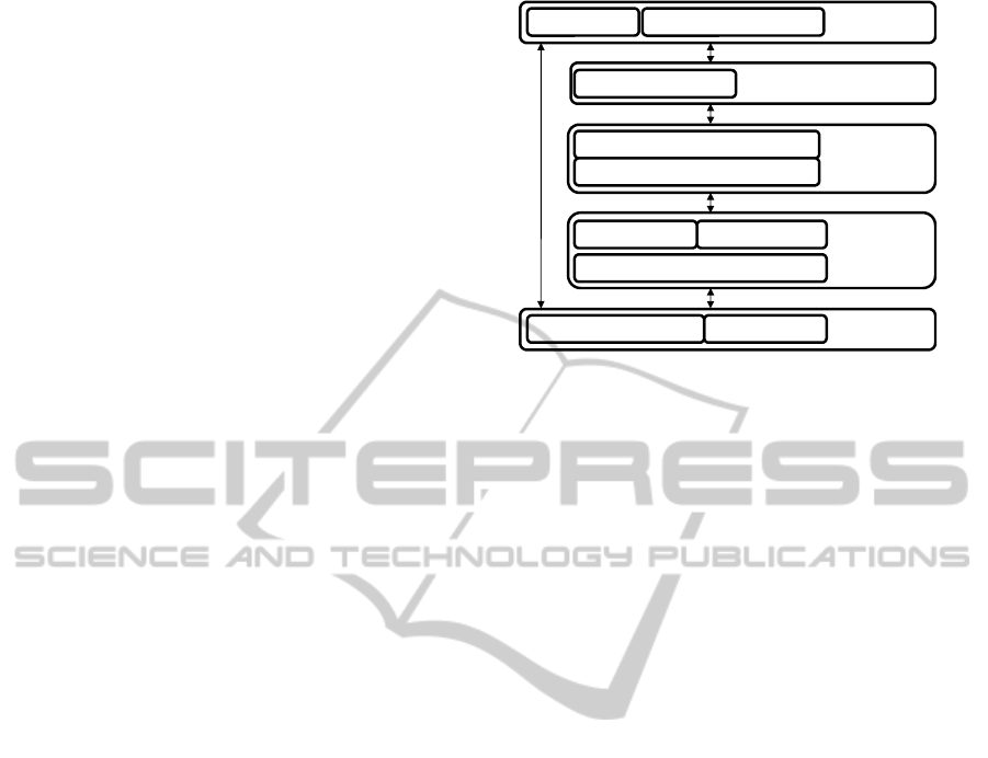
2 SIGA3D OVERVIEW
Our proposal is based on a semantic architecture
articulated in 6 levels (Figure 1). The import/export
level is dedicated to the parsing of various file
formats required to model the UIM from different
sources (GIS/BIM). The data model level makes it
possible the combination of geometrical data and
semantics. The level "contextual view" associates
user profiles and business rules to build contextual
LoDs. The connection level is mainly dedicated to
the streaming process between the databases and the
interface. The interface level displays the urban
environment into a 3D digital mock-up coupled with
a semantic tree of urban elements.
The innovative part of this architecture is mainly
contains in the data model level and contextual
views level. This part is the base of our semantic
LoD proposal. The first data model level part is
architecture of graphs representing the ontology,
allowing the context management and versioning of
the data (CMF for Contextual Model Framework).
Graphs operators are also defining to facilitate the
implementation of changes in conceptualization.
Figure 1: SIGA3D Architecture.
Information about reference systems for space
and time (CRS and TimeZone) are also managed in
this part. The other part defines a unified syntax-
based knowledge representation based on the
languages OWL, RDFS, and rules RuleML, SWRL
and described in this document in an expressive way
with description logic. It is called DMF (Data Model
Framework). DMF also contains operators for the
management of space and time and the definition of
local contexts that allow us to conduct a multi-
representation of data. The goal of this part is to
provide models used in inference engine to infer and
to check the data modelled by the CDMF modelling
operators.
3 DATA MODEL FRAMEWORK
The Data Model Framework is made of operators to
construct urban data models. These operators allow
the description of classes and properties that can be
used to define complex concepts using operators of
intersection, union, involvement, etc ...
The spatial data and especially georeferenced
coordinates do not make sense without the
knowledge of the coordinate reference system. This
information will appear in the next layer of our
architecture that manages the context of model
graph, to unify the management of coordinates. The
same kind of information is provided for time, with
the management of Time zones (Gutierrez et al.,
2007).
The management of local contexts, which allows
multi-representation, is done in this part by defining
new stamped operators, corresponding to the dmf
operators defined above. For example, script 1
defines three local contexts, designer,
structureEngineer and achievementDate. Script 2
3DEngine
DataLayer
Semantic LayerGeometric Layer
Semantic Viewer
SIGA3DInterface
SIGA3DConnexion
Streaming
SIGA3D
Contextual Views
View ManagementTool
ProfilManagementTool
SIGA3D Data
ModelFramework
SIGA3D
Import/Export
IFCDWG/DXF/DGN/GML
KMIS 2011 - International Conference on Knowledge Management and Information Sharing
360

defines several properties and a spatial
representation for a class ‘buildingPlan’ which
depends of the user. The contextual operators
dmf:[c
1
, …,c
n
]Class, dmf:[c
1
, …,c
n
]property and
dmf:[ c
1
, …,c
n
] spatialEntity are used.
<dmf:Class rdf:ID=’Profession’/>
<Profession rdf:ID=’designer’/>
<Profession rdf:ID=’structureEngineer’/>
<dmf:temporalEntity rdf:ID=’Day’/>
<dmf:property rdf:ID=’unitType’/>
<Day rdf:ID=’March’><unitType
rdf:resource=’#unitMonth/></Day>
Script 1: Definition of three local contexts.
<dmf:Class rdf:ID=’BuildingPlan’/>
<dmf:[designer]property
rdf:ID=’line_thick’/>
<dmf:[structureEngineer]property
rdf:ID=’wall_material’/>
<dmf:[designer]property
rdf:ID=’contains_plan’/>
<dmf:[designer,structureEngineer]property
rdf:ID=’contains_plan’/>
<dmf:spatialEntity rdf:ID=’the_plan’/>
<dmf:[designer]property
rdf:ID=’3D_plan’/>
<dmf:[designer,structureEngineer]property
rdf:ID=’2D_plan’/>
<the_plan rdf:ID=’plan_of_building_1’>
<url_2D_plan
rdf:resource=’/building/1/plan/plan2D.dwg’/>
<url_3D_plan
rdf:resource=’/building/1/plan/plan3D.ifc’/>
</the_plan>
<dmf:[designer,March]Class
rdf:ID=’Plan_availability’/>
<BuildingPlan rdf:ID=’building_plan_1’>
<line_thick
rdf:dataType=’&xsd;float’>10</line_thick>
<wall_material
rdf:dataType=’&xsd;float’>wood</wall_materia
l>
<contains_plan
rdf:resource=’the_plan’/>
</BuildingPlan>
Script 2: Example of contextual operators.
This example describes an object, BuildingPlan,
which has several properties. For a designer, the
BuildingPlan is defined with a line_thick, a plan
containing two representations. The same object is
defined differently for a structure engineer, with the
material of walls, wall_meterial, and an attached
plan with only one 2D representation.
4 CONTEXT MODEL
FRAMEWORK
This part of our architecture is composed of three
main blocks. The first block sets the context for each
graph of DMF, the second block defines a set of
graph operators to facilitate the writing and limit the
redundancy of data in the context management and
the third block defines a set of operators on graphs
to describe more accurately the geographical
information by defining relations between the
spatio-temporal data models of DMF. Context
management in this architecture is done by defining
a special graph called SystemGraph. A
SystemGraph is a graph or a set of graphs using
operators. These operators are graphs of the second
block of the CMF. The use of these operators can
simplify the management of the evolution of
knowledge of the model. So, rather than storing for
each modification of the model a new version of the
information, the CMF layer store the modification as
operations on graphs. The SystemGraph can be
describing using the following operators:
cdmf:graph connects graph and data. These data are
described according to the data model. They can be
a combination between other graphs using the CMF
graph operators AddGraph (union of graphs),
RemoveGraph, InterGraph, CompInterGraph and
MapGraph
cdmf:of represents the context. This property
defines a list of resources representing the access
context.
cdmf:model defines for a system graph the data
model which is used. This data model defines
elements which will appear in the graph.
cdmf:action defines user’s rights to access the data
(read/write/remove). If no action is defined in the
system Graph, which means that only the
visualization of the data is allowed.
cdmf :synchronizationGraph defines a list of Graph
depending of a special model where we define all
kind of spatial and temporal relationship between
data models.
cdmf:reference_frame defines the timezone and the
Coordinates Reference System (CRS) used for the
data model associated to the SystemGraph. These
values are valid for all data of the associated graph,
even if data sources are defined in another reference
system (in which case it is needed to make
transformations during the displaying phase of data).
The spatio-temporal synchronization is not a
common graph operator and is very specific to the
description of geographical information. It allows
INTEROPERABILITY BETWEEN GIS AND BIM - A Semantic-based Multi-representation Approach
361
defining the validity of a model by describing
relationships with other models. It can be used in
case of model evolution to assure the consistency of
the global model. For example, if we define a
building model and an electric power network
model, it is possible to describe a topological
relation between the two models to say they are
spatially connected. Then, when one of the models is
modified, for example to reposition the building
because of a bad georeferencing, we know we have
to modify the other model to keep the spatial
connection relation consistent.
5 CONCLUSIONS
This paper presents an ongoing research on the
definition of an Urban Modelling Architecture. This
paper focus on a new mechanism of LoDs called
contextual LoDs. It is the merge of classical
geometric approach to define LoDs and two
semantic multi-representations formalisms: the first
part is based on contextual trees to define user
profiles and business rules at the data model level.
The second part defines local contexts to allow
multi-representation at a lower level, i.e. for each
objects of the model. The concept of contextual
LoDs is designed to be integrated in an Urban
Facilities Management (UFM) platform. It is an
extension of the BIM concept for the management of
urban objects. Our framework facilitates data
maintenance (data migration, model evolution)
during the lifecycle of an urban environment and
reduces the volume of data with specific graph
operators. The urban approach also implies to
manage precisely the spatial and temporal
dimensions that have been considered in the
definition of the contextual LoDs part. This
approach is based on the CityGML 1.0 (Kolbe et al.,
2009) and IFC 2x3 standards.
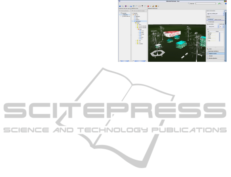
In the figure 2, a result of the integration of IFC
and GIS data (the IFC building is in red, and a
couple of buildings coming from GML file are in
blue) into the urban ontology can be seen.
Our future works will be to achieve the
implementation of our framework for the UFM
platform, including the contextual LoDs
management. These works are based on our previous
works on Active3d (Vanlande et al., 2008) and
designed to be fully compatible with both standards:
the one for geographic information (e.g. ISO/TC
211) and the second for the construction world (e.g.
ISO/PAS 16739).
Figure 2: Example of a 3D georeferenced scene with
multiple data sources.
REFERENCES
Campbell D. A., (2007), Building information modeling:
the Web3D application for AEC, Published in
Proceeding Web3D '07 Proceedings of the twelfth
international conference on 3D web technology, ACM
New York, NY
Döllner J., Hagedorn B (2007), Integrating Urban GIS,
CAD, and BIM Data By Service-Based Virtual 3D
City Models. 26th Urban Data Management Symp.,
Stuttgart, Germany
Gruber, T., R. (1993), A translation approach to portable
ontologies- Knowledge Acquis., 1993., pp 1-27
Gutierrez, C., Hurtado, C. A., and Vaisman A. (2007),
Introducing Time into RDF. IEEE Transactions on
Knowledge and Data Engineering, 19(2):207-218
Kolbe, T. H. (2009) Representing and Exchanging 3D
City Models with CityGML, Lee, Jiyeong / Zlatanova,
Sisi (Eds.), Proceedings of the 3rd Int.Workshop on
3D Geo-Information, Seoul, Korea. Lecture Notes in
Geoinformation & Cartography, Springer Verlag,
2009
Vanlande, R., Cruz C., Nicolle C. (2008) IFC and
Buildings Lifecycle Management", Journal of
Automation in Construction, Volume 18, Issue 1,
Elsevier, 2008, pp 70-78
KMIS 2011 - International Conference on Knowledge Management and Information Sharing
362
