
Reusable Software Units Integration Knowledge in a
Distributed Development Environment
M. Zinn
1
, K. P. Fischer-Hellmann
2
, A. Schuette
2
and A. D. Phippen
1
1
University of Plymouth, Plymouth, U.K.
2
University of Applied Science Darmstadt, Darmstadt, Germany
⋆
Abstract. Today’s software units (classes, components and services) require
large amounts of information during their development and use that can be docu-
mented for future reference, like documentation, multimedia files, specification,
and models. The availability of certain information, for example documentation,
is one of the factors that determines the capabilities of a unit, especially by reusing
it. Additional information is necessary and essential for the success of the en-
tire development process when applying certain procedure models, like Rational
Unified Process (RUP). Acquiring these units and their content is important for
reuse. However, this causes a problem in the area of global cooperation. Cur-
rently, approaches are missing that deal with software reuse in distributed soft-
ware reuse scenarios. Especially the problem of missing knowledge about inte-
gration of reusable software units in these scenarios has not yet been addressed.
This knowledge is also an important factor for reuse and reuse decisions. As a re-
sult software development teams locate at different locations my have problem to
integrate exchanged reusable software units. This paper discusses the challenges
of integration in distributed reuse scenarios by focusing on an industrial example
and create a model extension for a existing reuse system. As an result integration
of reusable software units can be done remotely without the necessary integration
knowledge.
1 Introduction
In object-oriented software development, various units of modeling are used. Typical
units are classes, components, and services [11]. Every unit type provides a certain
amount of information that is be used based on their underlying technologies, like ser-
vice description, documentation, or models [14]. In the scope of this paper, a compo-
nent is a deployed component. There are two important problems: development issues
related to a general view of these different units [11] and the decision to reuse a com-
ponent based on the available information [3]. Software Reuse Environments (SRE)
support software developers by addressing these problems. The general idea is to have
three important functions in one combined environment: reuse repositories, automatic
integration of software units, and the searching for these units. Current Integrated De-
velopment Environments (IDEs) are SRE systems. However, none of these approaches
completely fulfill the requirement of SREs to include all functions. [2]. Most of these
⋆
The authors would like to thank the French company Schneider Electric for providing infor-
mation about distributed existing software engineering scenarios.
Zinn M., P. Fischer-Hellmann K., Schuette A. and D. Phippen A..
Reusable Software Units Integration Knowledge in a Distributed Development Environment.
DOI: 10.5220/0003699000240035
In Proceedings of the 2nd International Workshop on Software Knowledge (SKY-2011), pages 24-35
ISBN: 978-989-8425-82-9
Copyright
c
2011 SCITEPRESS (Science and Technology Publications, Lda.)
SRE systems support the integration of information in a specified environment by us-
ing extensions that can directly communicate to a SRE system (e.g. Eclipse and Visual
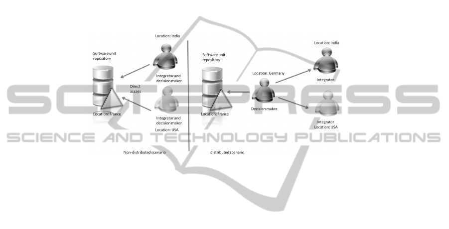
Studio). These functions can be used in distributed and non-distributed scenarios. Typi-
cally, in such a scenario, the decision maker, the person who decides to reuse a specific
software unit, is the same as the integrator, implementing the reuse. However, there are
scenarios in which the decision maker and the integrator are not the same person. In the
scope of this paper this is called a distributed scenario because the individuals can be
located in different locations and differ in their domain of expertise. Typically, software
architects are this kind of decision makers in software development [4]. Figure 1 shows
these focused scenarios:
Fig.1. Distributed and Non-Distributed Scenario.
The authors of this paper hypothesize that the reuse of software units in a distributed
scenario has a negative influence on the reuse. These negative impacts can be mitigated
by providing an integration model and a service based communication architecture to
achieve the integration. Challenges of the distributed software reuse scenario will be
discussed in this paper. The aim of this paper is to provide a solution for distributed
software reuse scenarios that can be used to support software development. This is
achieved by extending an existing software reuse architecture to include an integration
model. This solution is the result of research into Service-based Software Construction
Process (SSCP) incorporated into the field of SRE and the software unit reuse with lim-
ited knowledge. This paper’s heuristic value lies within the enhancements to existing
SOA-based (Service Oriented Architecture) architectures (SSCP System) by support-
ing the handling of units of modeling, like classes, components, and services, for use
by decision makers with integration tasks. The paper concludes with the fact that sup-
porting distributed scenarios can be done with an integration extension of the SSCP
system.
2 Two Problems in a Distributed Reuse Scenario
2.1 Problem Identification
Distributed software development scenarios cause special problems in Software Archi-
tecture, Engineering Processes, and R&D Organisation [1]. Especially the sharing of
reusable software units between teams have a deep impact on costs:
25

“
A problem observed [...] is that when decoupling between shared software assets is
insufficiently achieved is excessive coordination cost between teams. One might expect
that alignment is needed at the road mapping level and to a certain extent at the planning
level. When teams need to closely cooperate during iteration planning and have a need
to exchange intermediate developer releases between teams during iterations in order
to guarantee interoperability, the coordination cost of shared asset teams is starting to
significantly affect efficiency.
” [1]
To get an impression of the problems that may exist in a distributed reuse scenario,
it is helpful to observe an real life industrial scenario. For this, data from the company
Schneider Electric is used [8]. Information about used technology and methodologies is
provided by project leaders of Schneider Electric): Schneider Electric is a French com-
pany that focuses on the automation and energy industries. Employing approximately
130,000 people, divided into over 100 organisations, Schneider Electric is divided into
in 5 different domains: Building, Industry, Power, IT, and Energy. Each domain has
locations all over the world in many different countries. In each of these domains, soft-
ware development is an important part of the work and the provided software solutions.
Typical software development areas are server-, desktop-, web-, and embedded device
applications. Various locations work together to fulfil a task and provide a software
solution. Thereby, typical units of modelling (like classes, components, and services),
implemented in different technologies, are used (like .NET or Java). Schneider Electric
uses the typical component worlds (see [10]). Each location uses its own repository for
these units. However, the repository types and their usage differs. The authors analysed
6 software development projects of Schneider Electric from 2006 to 2010 that uses
a distributed scenario (limited to two locations) evaluating four different aspects: (1)
Which partner is developing the Software?, (2) Which partner is making architectural
decisions?, (3) Which partner is selecting reusable software units?, and Which partner
is integrating the selected reusable software units?
The result of this analysis can be describes as follows: (Answer Q1 and Q2) The
characteristics of the analysed scenario include that the partner who selects the reusable
components is not the partner who is doing software development. Most time Indian
software development teams were responsible and team from other countries are the
software designer making architecture decisions.(Answer Q3) Also selecting of reusable
software units, like corporate identity or login components are selected by the non de-
veloper teams. (Answer Q4) In each analysed project the integrating task was done by
the software development team. The previous analysis shows a distribution pattern. The
development task and the development decisions are done by separated teams located
in different countries. Such patterns include different problems. In the following section
the problem of accessibility and integration will be discussed and analysed.
2.2 Accessibility Problem
The accessibility problem for software unit reuse can be explained using the Software
Reuse Information Demand Model (SRID) [13], that is based the Information Demand
Model [6]. From the SRID point of view of information depends on five factors :
26
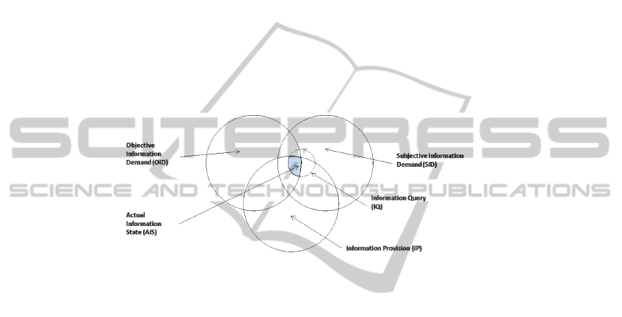
– Objective information demand: This is the entire (theoretical) amount of informa-
tion that can solve a problem.
– Subjective information demand: This is all information that the user believes can
solve the problem.
– Information provision: This is all information that is accessible.
– Information request: This is a search request the user formulates to find information
relevant for solving the problem.
– Real level of information: This is all information that is correct, is available to the
user, is accessible, and is requested by the user.
All these 5 factors are part of the Software Reuse Information Demand model (see
Figure 2). The general problem of information demand arises because the real level of
information is a subset that is limited by the user’s ability to formulate the request (Real
level of information). Figure 2 shows the relationship between the five factors.
Fig.2. SRID model [13] (based on [6]).
In the area of accessibility this problem can be identified when a user has to search
for a reusable software unit in an external environment. Missing knowledge about a
providing system (repository) limits the information request [9]. The user is less able
to formulate a request. The severity of this problem comes from most users being ju-
nior,inexperienced software developers [9]. Another accessibility problem occurs when
the user has no access to the software reuse environment of another location. This is
an information demand problem based on infrastructure requirements. In the case of
Schneider Electric, both accessibility problems occur.
2.3 Integration Problem
A user who wishes to integrate a reusable software unit has to know about the dependen-
cies, structure, configuration and technology of the unit. Especially configuration has
been a problem for some years [7]. This limits the overlapping area between subjective
and objective information demand (See Figure 2). The result is a strong limitation of
the real level of information. This is demonstrated in the following simple example: In
the initial situation the reusable component library for discovery device profile based
web service is a .Net library called ’Discovery.dll’. It uses another reference called
’DPWS.dll’ that is an unmanaged .NET library and includes some specific libraries that
are used by the Discovery.dll file. A configuration file is required (’Config.xml’) that has
27

to be placed in the same directory as the Discovery.dll file. By using Visual Studio, the
user has to perform following integration steps to create this setup:
1. add the Discovery.dll as a reference, because of the user will require functions,
structure, user interfaces or data from this library.
2. write a script to copy
DPWS.dll
in the release directory after compiling, because
of the unmanaged libraries can not be easily managed by the IDE.
3. add the
Config.xml
to this project and set the copy attribute to “
Copy if newer
”,
because of this file contains settings that will be used during runtime.
This example illustrates the complexity of software unit integration for a specific
environment. If the user is unaware of these integration steps, the process is likely to be
time consuming. Therefore, the problem of integration is to know these additional setup
steps. Each reusable unit needs further steps for integration. In a distributed scenario the
individual who is aware of these steps cannot be in a different location. In this case the
integration problem is also a problem of information demand.
3 Solution Approach
Approaching the problems involves two different models. The first is an integration
model and the second an architecture extension to support distributed scenarios. The
model, the architecture, and the combination to support distributed software unit reuse,
constitutes the scientific contribution of this paper.
3.1 An Integration Model as Reuse Model Extension
In the context of the underlying research, the authors developed an ontology to the
subject ’Service-based Software Construction Process’ in order to counteract the prob-
lems experienced in software unit reuse [14]. Also an environment was build using this
ontology and enabling users to do software unit reuse (focusing search, adaption, and
IDE integration of units) without the complete necessary knowledge. The used ontol-
ogy serves only the unified description of units of modelling (classes, components and
services). This includes the description of technological facts (components, services,
etc.).
The ontology consists of 4 parts. Part 1 shows the access to the ontology: The
problem-solution approach’ Part 2 relates to ’general business information’ about the
solution (e.g., manufacturer, name, and author). Part 3 describes the solution as a tech-
nical unit (e.g., a type of unit, a technology, a file format, or files). In Part 4 the technical
contents are described thereby explaining a semantic search approach that is discussed
in a previous publication (See [15]). If an instance of the ontology is generated (e.g.,
by the registration of a newly developed unit), the user has to specify information that
is stored in the appropriate area of the ontology. The data may also be entered auto-
matically into Part 3 of the ontology. This is possible as the technical data is generally
detectable (such as file size, file type, file name, and technology). Nevertheless, the
data from other sections of the ontology is not automatically detectable. The ontology
28
describes services, components, and classes in the same way and abstracts them into
units (unit view). Based on this abstraction, the ontology will be extended by collection
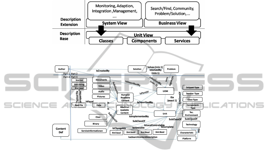
requirements of different use cases (called views). Figure 3 demonstrates this relation-
ship.
Fig.3. Description layers of the Service based Software Construction Model.
Fig.4. SSCP Model Section 3 - Technical Descriptions.
The following section displays and further describes modelling of the integration.
This corresponds to Part 3 of the ontology. Moreover, it is focused on the problems
indicated in Section 2. Figure 4 shows Part 3 of the ontology in a simplified way, de-
scribing the technical building of a unit. The ’UOM’ entity is the main part of the on-
tology. This entity is linked with the ’Unit’ entity on equal terms. ’Unit’ is described in
multiple ways, the first being the technical presentation broken down into four smaller
entities (’Snippet’ for code units, ’Service’ for service-based units, ’Class’ for object-
oriented class units, and ’Component’ for deployed software components). The file con-
tent of a unit can be classified as either machine-readable or human-readable content.
The machine-readable content is a set of files (the ’File’ entity) that can be further
classified by their usage content (code fragment, class, binary code, and service infor-
mation). These usage entities are linked to the technical presentation. The other content
of a unit is shown by the human readable content entity. This entity represents files that
are further classified by the presentation mode (document, video, audio, and picture).
The final piece of the unit is the technology description, for which a simple approach
has been selected. The ’Unit’ entity has a relationship to the ’Environment’ entity that
is described through the ’Platform’, ’Technology’ and ’Programming language charac-
teristic’. For example, a component may depend on the .Net framework (based on the
32-bit variety) and the C# programming language.
29

A unit has been represented as a common description of classes, components, and
services and will now be extended with integration information. The ’Real File’ node
in the base semantic model may have instances of integration descriptions. Each node
in the semantic model contains a unique identifier (ID) and a friendly name property.
This is not sketched in Figure 5. Three questions have to be answered in relation to unit
integration (Questions are defined from the result of the component analysis of [5]):
(1) What is the target platform? (2) How should the unit be integrated? (3) What is the
scope of the unit?
The target platform has to be validated before integration can proceed. This is crit-
ical, as the current research of the extension model includes parts that are platform
dependent. A platform is marked by the ’IDE’ node that has a relation to the ’environ-
ment’ mode of the base model. The meaning of this relation is that the ’IDE’ shows
which kind of environment can be used to host, build, and execute a software unit. The
’Real File’ node has an indirect relation (given by the base model) to an ’Environment’
node. This relation describes the appropriate environment to use with this unit. From
the semantic point of view, the ’Environment’ node can be used to validate the compat-
ibility between a software unit and the platform of the IDE. For example, a class file
that requires the .NET framework is generally not compatible with a Java-based envi-
ronment (such as Eclipse). The process of integration can be illustrated by detailing the
various integration patterns of the Visual Studio and Eclipse APIs. The following con-
cepts are necessary from the view of the authors and are provided in both environments
Visual Studio.NET and Eclipse (handling in the two environments differs):
– OnlyCopy: This copies a file without referencing it in the solution tree of the
project. This is necessary for second level dependencies that are not controlled by
the IDE environment.
– WebReference: This marks a file as a web reference. Different IDEs utilize different
methods to manage this information. For example, Visual Studio can use a WSDL
file to create a reference to a web service that is based on the corresponding WSDL
description.
– Reference: This copies a file and includes it in the solution tree of the project. This
is a traditional reference that can be included or imported. This is necessary for
managing the dependencies of a unit.
– DoNotCopy: This prevents a file from being transferred into a project’s environ-
ment. All files a unit includes are not necessarily required by the IDE (e.g., docu-
mentation).
– InsertAsText: This flags the content of a file to be treated as text when loaded into
the IDE. This is useful for code references (using or import) and code snippets.
– CopyAsResource: This flags a file to be used as a resource and includes it in the
project (e.g., configuration files).
The scope of the unit is used to create integration packages. For instance, a library
refers to another library as a dependency, so both libraries have to be delivered. This
relation can be modelled by referring an “Integration package” node to the global “unit”
node. A unit is now part of an integration package. Each of these packages includes files
with integration descriptions that are related to an instance of the integration package.
30
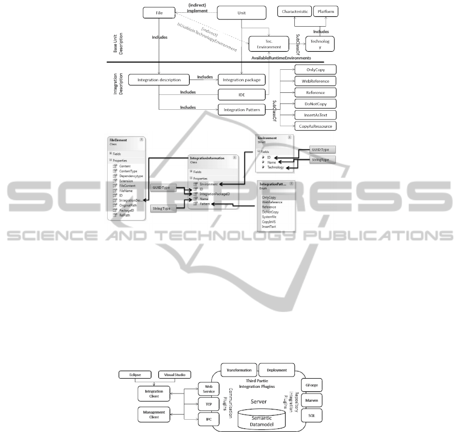
Fig.5. Integration model extension of Figure 4 (top) and data model variation.
Figure 5 shows a model integration extension in relation with the normal unit descrip-
tion.
3.2 Architecture Extension
In a previous publication, [12] an architecture of a service-based software construction
CASE- tool was sketched. Figure 6 shows an overview of this sketched architecture:
Fig.6. Communication Architecture extended version of [12].
The architecture is used to implement a distributed system that deals with the un-
derlying topic of missing knowledge in software reuse (see Section 1). It is capable
of integrating existing software unit repositories and handles them within the seman-
tic model. The server side of this architecture provides different functions like search,
management, transformation, and deployment of software units. On the client side a
management client and an integration client are sketched. In contrast to the manage-
ment client, the development client does not influence the artefacts (groups of software
units with the same business context), such as the deletion of an artefact or software
31
unit on the server. Besides searching for artefacts or units of modelling, the develop-
ment client is responsible for the transformation and the integration of transformation
results into the current development project. In this described scenario the integration
client communicates directly to the server. This belongs to a non-distributed scenario.
The user searches, selects, and integrates software units into the project, using the in-
tegration client which is hosted in the IDE (or the host system). This architecture will
be extended by adding an integration plugin next to the Deployment and Transforma-
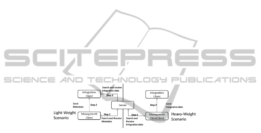
tion. Analysing the scenarious of Figure 7 two distributed scenarios c are identified by
the authors using the infrastructure given by the architecture of Figure 6: Light-weight
scenario: The integration client receives metadata from the management client about
the unit(s) that are to be integrated. The integration client is able to do a specific search
on the server with a single unit as a search result. Heavy-weight scenario: The man-
agement client sends the integration information directly to the integration client; there
is no need for the integration client to communicate with the server.
The two scenarios differ in the amount of data which has to be exchanged between
the management client and the integration client. In the light-weight scenario, the man-
agement client sends only metadata to the integration client. Therefore, the integration
client can perform the search. In the other scenario, all data required for integration is
sent. Figure 7 illustrates both scenarios:
Fig.7. Light- and Heavy-weight scenario.
Based on the integration extension for the semantic model (see Section 3.1) a data
model can be created for communications. [12] shows an XML description of data
entities that is used in SOAP based communication between clients and the server.
Figure 5 shows the data model that is used for integration.
Based on the light- and heavy-weight scenarios, a service for the integration client
can easily be defined. The light-weight scenario involves the integration client requir-
ing the meta data and the ID of the integration package of the unit (see Figure 5).
A unit includes all references to file elements, allowing the client to request specific
information about the unit from the server. The heavy-weight scenario requires the
integration client to know a set of integration information. Therefore, all files and
an ID for an integration package is required which describes the integration of the
files (see Figure 5). An web service interface supporting both scenarios (based on the
data model of Figure 4) may described as into two operation: GetIntegrationDataL-
ightWeigth(Guid serverID, Guid artefactID, UOM unit, Guid integrationPackageID)
and GetIntegrationDataHeavyWeigth(FileElement[] setOfIntegrationFiles, Guid inte-
grationPackageID).
32

4 Example Scenario Discussion
As discussed in Section 3, the paper focuses on the problems of accessibility and inte-
gration. Section 4 now addresses a definition of a problem approach. The relationship
between both discussions can be demonstrated with a simple comprehensive example.
Given the scenario of Schneider Electric (see Section 2.1), two teams situated in dif-
ferent locations (French and India) are working together on a software development
project. The French team is defining the architecture and preselecting existing software
units that are developed by the same team. The Indian team is responsible for the real
implementation and integration (see Figure 1). Integration Problem: The team in India
has no information about the structure and the dependencies of the reusable software
units. Learning to integrate these units would take a considerable amount of time. By
using the focused architecture and integration model of Section 3, the team can use the
integration description for automatic or manual integration. As a result, the integration
team needs less knowledge about the integration of a specific reusable unit. However,
this is only possible if integration descriptions are available. So the French team have
to insert the information in the SSCP environment. But only one time. Accessibility
Problem: The architecture extension discussed in Section 3 allows the French team
to send information to the team in India. They may send only unit meta-information
(light-weight scenario) or they may send the complete unit description including all in-
formation for integration (heavy-weight scenario). In the first case, the Indian team has
information about the unit, but they have to connect and use the repository tool of the
French team. This only solves one a part of the accessibility problem, because this team
has to know how to access the repository system. They are however, able to formulate
a query for this system. In the second case, the Indian team can directly integrate the
unit without accessing the repository tool (see Figure 1). This result is very important.
The Indian team does not need to access this repository. The accessibility problem de-
scribed in Section 3 can be described by the questions ’Where is the repository?’, ’How
to access it?’, and ’How to use it’. At this point the Indian team does not need to handle
the repository because of the other team is doing this. As an result the different question
does not occur.
Another interesting result is reuse of this integration knowledge. After the French
team added the knowledge to the SSCP system. it is reusable at any time. Different
teams located around the world can be supported.
The example discussion shows that both scenarios (light and heavy-weight) may be
resolved by the solution described in Section 3. However, this depends on the availabil-
ity of an integration model and the distributed scenario in use.
5 Conclusions
This paper demonstrates the problems of accessibility and integration when using a dis-
tributed industrial scenario. This scenario deals with projects that reuse software units
and is implemented by two teams in differentlocations. Accessibility is a problem if one
team requires access to the repository system of another team without having knowl-
edge of the tool. Accessibility is also a problem, if there is no access to a repository
33

system. Integration becomes a problem if the integration team has no knowledge about
the structure and dependencies of the reusable software unit. All problems are based on
missing information. The result of these problems is a negative influence on software
unit reuse (as it may increase integration time, etc.). This illustrates the importance of
information in software unit reuse. A described problem approach uses an extended
semantic model that describes different software units (classes, components, and ser-
vices) in a unified way. This extension describes data that is needed to integrate Studio
and Eclipse. Based on this, a distributed architecture of a software reuse environment
was extended to solve the discussed problems (accessibility and integration). The ac-
cessibility problem is solved by using the architecture to get the integration information
without the need of connecting to a repository system. The integrationproblem is solved
by providing the integration information as part of the description of the reusable soft-
ware unit. The model combined with the architecture is the described novelty of this
paper. This paper arrives at the conclusion, that the discussed accessibility and integra-
tion problems can be solved by providing the correct meta-information and technical
infrastructure to deliver the information. Integration of reusable software units should
not need expert knowledge. However, this paper only discuss a solution. The created
model and architecture extension should be tested in a additional case study by ad-
dressing the advantages for software developers in more complex distributed scenarios.
References
1. Jan Bosch and Petra Bosch-Sijtsema. From integration to composition: On the impact of
software product lines, global development and ecosystems. Journal of Systems and Soft-
ware, 83(1):67–76, 2010.
2. Vinicius C. Garcia, Eduardo S. de Almeida, Liana B. Lisboa, Alexandre C. Martins, Silvio
R. L. Meira, Daniel Lucredio, and Renata P. de M. Fortes. Toward a code search engine based
on the State-of-Art and practice. In 2006 13th Asia Pacific Software Engineering Conference
(APSEC’06), pages 61–70, Bangalore, India, 2006.
3. Slinger Jansen, Sjaak Brinkkemper, Ivo Hunink, and Cetin Demir. Pragmatic and oppor-
tunistic reuse in innovative start-up companies. IEEE Software, 25(6):42–49, 2008.
4. Philippe Kruchten, Rafael Capilla, and Juan Carlos Dueas. The decision view’s role in soft-
ware architecture practice. IEEE Software, 26(2):36–42, 2009.
5. Jingyue Li, Reidar Conradi, Christian Bunse, Marco Torchiano, Odd Petter N.Slyngstad, and
Maurizio Morisio. Development with Off-the-Shelf components: 10 facts. IEEE Software,
26(2):80–87, 2009.
6. Arnold Picot. Die grenzenlose Unternehmung: Information, Organisation und Management
Lehrbuch zur Unternehmensfuehrung im Informationszeitalter. Gabler, Wiesbaden, neuaufl.
edition, 2003.
7. Marcello Rosa, Wil M. P. Aalst, Marlon Dumas, and Arthur H. M. ter Hofstede.
Questionnaire-based variability modeling for system configuration. Software & Systems
Modeling, 8(2):251–274, 2008.
8. Schneider-Electric. Schneider-Electric website. http://www.schneider-electric.com, Septem-
ber 2010.
9. Sajjan G. Shiva and Lubna Abou Shala. Software reuse: Research and practice. In Fourth
International Conference on Information Technology (ITNG’07), pages 603–609, Las Vegas,
NV, USA, 2007.
34

10. Clemens Szyperski. Component software: beyond object-oriented programming. ACM Press
Addison-Wesley, New York, London, Boston, 2nd ed., 2002.
11. G. Wang and C. K. Fung. Architecture paradigms and their influences and impacts on
component-based software systems. In 37th Annual Hawaii International Conference on
System Sciences, 2004. Proceedings of the, pages 272–281, Big Island, Hawaii, 2004.
12. M. Zinn, K. P. Fischer-Hellmann, and A. D. Phippen. Development of a CASE tool for the
service based software construction. pages 134–144, Plymouth, 2009. Centre for Information
Security and Network Research.
13. M. Zinn, A. Schuette K. P. Fischer-Hellmann, and A. D. Phippen. Information demand model
for software unit reuse. In The Proceedings of the 20th International Conference on Software
Engineering and Data Engineering, pages 32–39, Las Vegas, June 2011.
14. M. Zinn, G. Turetschek, and A. D. Phippen. Definition of software construction artefacts for
software construction. pages 79–91, Plymouth, 2008. Centre for Information Security and
Network Research.
15. Marcus Zinn, K. P. Fischer-Hellmann, and Alois Schuette. Finding reusable units of mod-
elling - an ontology approach. In Proceedings of the 8th International Network Conference
(INC’2010), pages 377–386, Heidelberg, July 2010.
35
