
DEVELOPMENT OF SEQUENTIAL ASSOCIATION RULES FOR
PREVENTING MINOR-STOPPAGES IN SEMI-CONDUCTOR
MANUFACTURING
Sumika Arima, Ushio Sumita and Jun Yoshii
Graduate School of Systems and Information Engineering, University of Tsukuba
Tennoudai 1-1-1, Tsukuba, Ibaraki 305-8573, Japan
Keywords:
Semi-conductor manufacturing, Minor-stoppages, Sequential association rules, Preventive maintenance
policies.
Abstract:
In semi-conductor manufacturing, the machine downtimes due to minor-stoppages often exceed 40% of the
working hours of a day, and would amount to the huge loss. However, effective methodological tools for
predicting and preventing the minor-stoppages are hard to come by. The purpose of this research is to fill this
gap by establishing effective preventive maintenance policies for controlling minor-stoppages. Our approach
is to develop association rules based on sequential data along the time axis so that the resulting rules could be
used for predicting occurrences of certain minor-stoppages. The proposed methodology is applied to a real
data set and yields two preventive maintenance policies in a concrete form, thereby demonstrating its power
and usefulness. While the paper focuses on the testing process, the methodology proposed in this paper is
valid for other production processes, provided that similar sequential data could be collected.
1 INTRODUCTION
Semi-conductor manufacturing is characterized by a
sequence of sophisticated manufacturing processes,
often exceeding several hundred production steps.
Such processes possess both aspects of continuous
and discrete operations. On one hand, many pro-
duction steps involve chemical diffusion for etch-
ing layers of circuits and such steps ought to be
controlled continuously. On the other hand, the
final products are semi-conductor chips which are
clearly discrete in nature. Combined with necessary
ultra-precision technologies, these factors make semi-
conductor manufacturing extremely difficult to con-
trol and force one to rely upon quite expensive auto-
mated production machines. Accordingly, the cost of
machine downtimes in semi-conductor manufacturing
is quite huge. When a major failure of a production
machine occurs, vender engineers have to be often
called in and the repair may sometimes take more than
a few days.
Apart from such major failures, in semi-conductor
manufacturing, the machine downtimes due to minor-
stoppages would also amount to the huge loss. A
minor-stoppage is defined to be a machine failure
which requires the direct involvement of an operator
for repair but the repair time is quite short once the
problem is addressed by the operator. Frequency of
minor-stoppages is typically quite high and it is not
rare to have multiple minor-stoppages occurring si-
multaneously. Since one operator deals with several
machines, a machine with a minor-stoppage may have
to wait until it is attended by the operator. Because
of such waiting times, the machine downtimes due
to minor-stoppages often exceed 40% of the working
hours of a day. Accordingly, it is extremely important
to develop effective ways for controlling such minor-
stoppages.
In the literature, the issue of enhancing the yield
and reducing the machine downtime in manufacturing
has been addressed largely from the point of view of
detecting root-causes of the product defects based on
some data mining techniques. (Gardner and Bieker,
2000), for example, employ a combination of self-
organizing map neural networks and rule induction
to identify the critical poor yield factors in the wafer
manufacturing process. In (Chen et al., 2005), cor-
relations between combinations of machines and the
defective products are first analyzed. The technique
of association rule mining is then used to establish the
root-cause machine identifier efficiently. (Chien et al.,
2007) focus on the wafer fabrication process and chal-
349
Arima S., Sumita U. and Yoshii J..
DEVELOPMENT OF SEQUENTIAL ASSOCIATION RULES FOR PREVENTING MINOR-STOPPAGES IN SEMI-CONDUCTOR MANUFACTURING.
DOI: 10.5220/0003713503490354
In Proceedings of the 1st International Conference on Operations Research and Enterprise Systems (ICORES-2012), pages 349-354
ISBN: 978-989-8425-97-3
Copyright
c
2012 SCITEPRESS (Science and Technology Publications, Lda.)
lenge the problem of detecting root-causes based on a
Kruscal-Wallis test, K means clustering and the vari-
ance reduction approach.
While these contributions may enable one to iden-
tify the correlation structure between combinations of
machines and the defective products, and detect root-
causes of the defections, they do not provide preven-
tive maintenance policies automatically. In particular,
in semi-conductor manufacturing, effective method-
ological tools for preventing the minor-stoppages are
hard to come by. Part of the reason for this difficulty
may be found in that there are many differentpotential
sources of minor-stoppages. Certain minor-stoppages
may be attributed to factors related to products, in-
cluding shape, size, weight, pins, and the like. De-
terioration of machine conditions may cause minor-
stoppages. HR (Human Resource) related factors
such as work-shifts, skills of workers and training
programs would also affect minor-stoppages.
The purpose of this paper is to establish ef-
fective preventive maintenance policies for control-
ling minor-stoppages in semi-conductor manufac-
turing. Our approach is to first classify types of
minor-stoppages based on real data. These types
are categorized in such a way that, once a type
of a minor-stoppage is identified, the cause of the
minor-stoppage could be located with high proba-
bility. The next step is to analyze a sequence of
minor-stoppages by types where occurrences of cer-
tain minor-stoppages would be recognized to trigger
minor-stoppages of other type, thereby providing a
foundation for establishing preventive maintenance
policies. This kind of the association rule approach is
prevalent in marketing and is often employed for dis-
covering purchasing patterns to be expected with high
probability. The uniqueness of this paper is to de-
velop such association rules based on sequential data
along the time axis so that the resulting rules could
be used for predicting occurrences of certain minor-
stoppages.
The structure of this paper is as follows. The test-
ing process in SAW (Surface Acoustic Wave) man-
ufacturing is described in a succinct manner in Sec-
tion 2. Along with the testing process, 10 minor-
stoppages of principal interest are explained in detail.
Section 3 is devoted to establish the association rules
for predicting occurrences of such minor-stoppages.
Numerical results are provided in Section 4 based on
real data, demonstrating the practical usefulness of
the proposed approach. Some concluding remarks are
given in Section 5.
Throughout the paper, vectors are indicated by un-
derbars, e.g. a
T
= [a
1
,...,a
N
], etc.
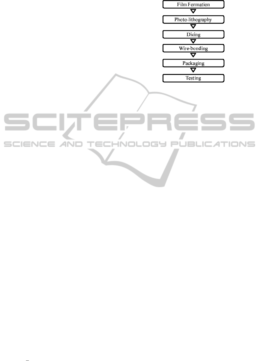
Figure 1: Six major stages of SAW manufacturing pro-
cesses.
2 SAW MANUFACTURING
PROCESS
We consider the manufacturing process of SAW fil-
ters, which are used in mobile phones, optical routers
and the like for screening out electronic signals out-
side a pre-specified frequency range so that elec-
tronic noises can be eliminated in communication.
The manufacturing process consists of six production
stages as depicted in Figure 1.
The first stage is to cover the surface of each sil-
icon wafer with a thin film through chemical vapor
deposition, followed by photo-lithography to create
a circuit pattern within the silicon wafer. These two
stages are repeated so as to form a layer of circuit
patterns. Then individual silicon wafers are cut into
chips through dicing. In wire-bonding and packag-
ing, each chip is mounted onto a metallic lead-frame
and is covered by a cap. All of the finished products
then go through complete testing before shipment to
customers. In this paper, we focus on the testing stage
and establish preventive maintenancepolicies for con-
trolling minor-stoppages within the testing procedure.
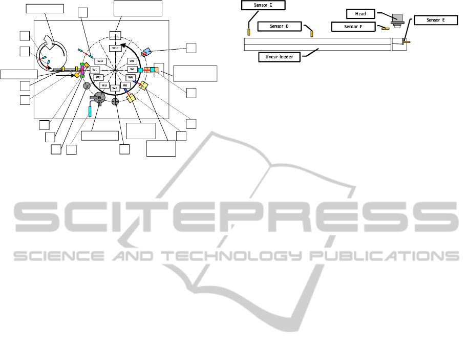
The structure of a testing machine is depicted in
Figure 2 for facilitating the explanation of the de-
tailed operations involved in the testing procedure.
Here, sensors A through N are indicated by putting
each of them in a square. In line with the conven-
tion, throughout the paper, we call a finished product
“a work”. Several thousands of works constituting a
lot are first placed into the bowl-feeder, which rotates
counter clockwise so as to feed works into the linear-
feeder. Sensors A and B located near the entrance
to the linear-feeder examine whether or not the right
face of a work is placed up. If Sensor A detects a
work with face down, it turns on the system to flip the
work over by blowing air. If the work is still judged
ICORES 2012 - 1st International Conference on Operations Research and Enterprise Systems
350
Bowl-feeder
Linear-feeder
Pre-Alignment
Frequency
Testing
Ejection of
Defect Products
Retrieval of
Finished Products
C
D
E
F
G H
I
J
K
L
M
N
A
B
Insulation
Testing
Figure 2: Structure of a testing machine.
as its face down by Sensor B, it would be blown back
to the bowl-feeder by ejecting air.
At the entrance of the linear-feeder, Sensor C de-
termines whether or not a work is there. The first work
fed into the linear-feeder would turn on the vibra-
tion system which facilitates all the works within the
linear-feederto be movedforward toward the entrance
to the wheel mechanism. Since the wheel mechanism
rotates around 12 fixed stations located in equal angu-
lar positions with fixed time interval, we name the 12
stations Wi, i=1, 2, c , 12 in sequence counter clock-
wise. Upon reaching W1, a work is sucked into one
of the 12 heads of the wheel mechanism to be moved
counter clockwise to W2, W3, etc.
There are two types of minor-stoppages possible
in the feeding process. The first case is that the bowl-
feeder is stuck and the linear-feeder is starved. The
second case is due to completion of the entire lot of
works, which requires a new lot of works to be fed
into the bowl-feeder. The former is called “PF-Stuck
Al” where PF stands for Parts Feeder and Al means
Alarm, while the latter is named as “WC Al” with
WC describing Work Completion. In order to cope
with PF-Stuck Al and WC Al, Sensors D, E and F are
employed as shown in Figure 3. Sensor D is located at
the point of the ten work length from W1. Sensor E is
attached to the stage of W1, and Sensor F is installed
at the up position of a head of the wheel mechanism
above W1. PF-Stuck Al is detected if Sensor F signals
no work present 10 times in a row under the condi-
tion of either “Sensor D identifying the presence of a
work and Sensor E signaling non-existenceof a work”
or “Sensor E recognizing the presence of a work”.
WC Al is detected if either “Sensors E and F signal
non-existence of a work simultaneously 10 times in a
row” or “Sensor F signals non-existence of a work 15
times in a row”. Sensor F would also see if the work
is sucked in an appropriate position. If not, “WS-F
Al” is detected where WS-F stands for Work Supply-
Figure 3: Locations of sensors along the linear-feeder.
Failure. Upon detecting PF-Stuck Al, WC Al or WS-
F Al, the testing machine is automatically stopped and
the appropriate alarm is signaled. This alarming pro-
cess is similar for other minor-stoppages and will not
be mentioned hereafter.
Upon reaching W2, a work remains to be sucked
to the head and Sensor G of W2 checks if the work
is there and the bottom of the work shows the cor-
rect side. If the bottom side is correct, R-at-W2-Flag
is set to be 1 where R stands for Recognizable. In
this case, it is also checked to see if the horizontal
position of the work is appropriate, finding the cor-
rective rotational angle to be implemented at W3, if
necessary. If the bottom side is found to be wrong,
R-at-W2-Flag is set to be 0. At W3, as soon as a work
is placed back to the stage with the corrective rota-
tion if necessary, a vacuum sensor called Sensor H is
activated. If the work was not sucked appropriately
to the head previously and was not corrected at W3,
it would not cover Sensor H completely, resulting in
air leak. In this case, “PASM Al” is signaled, where
PASM means Pre-Alignment Sucking Miss. At W4,
Sensor I similar to Sensor G is switched on. If the two
sensors do not produce consistent judgment concern-
ing the presence of a work, PASM Al is also reported.
When the work is placed 180in a wrong direction, the
above air leak test may still be passed. If Sensor I de-
tects this case, R-at-W4-Flag is set to be 0. Otherwise,
it is set to be 1.
At W5, each work is tested to see if its frequency
falls into the pre-specified range. If the test is success-
ful, F-Flag is set to be 1 with F meaning Frequency.
Otherwise, it is set to be 0. Upon completion of the
test, Sensor J is turned on to make sure that the work
is moved to W6. If Sensor J detects the work left on
the stage of W5, “WL-at-W5 Al” is issued where WL-
at-W5 stands for Work Left at W5. W6 is to check if
the insulation functions properly. Upon completion of
the insulation test, I-Flag is set to be 1 if successful,
and 0 otherwise, where I stands for Insulation. As for
Sensor J at W5, Sensor K at W6 is then set on to see
whether or not the work is transferred to W7 appro-
priately. If not, “WL-at-W6 Al” is reported.
Sensor L is activated at W7 to see if there is a work
on the stage of W7. If it reports non-existence of a
work despite Sensor F reported otherwise, “SM Al” is
issued where SM stands for Sucking Miss. If any of
DEVELOPMENT OF SEQUENTIAL ASSOCIATION RULES FOR PREVENTING MINOR-STOPPAGES IN
SEMI-CONDUCTOR MANUFACTURING
351

R-at-W2-Flag, R-at-W4-Flag, F-Flag and I-Flag has
the value of 0, the work is detected as a defect at W7.
Such defects are sorted according to the values of the
flags and are dropped into appropriate cells. Sensor
M checks the presence of a work at W8. If it finds
a work, the values of R-at-W2-Flag, R-at-W4-Flag,
F-Flag and I-Flag for the work are examined. If any
of them is 0, it means that the work is failed to be
detected as a defect at W7 and “FDD Al” is issued
where FDD means Failure to Detect a Defect. After
W8, each work is passed over to W9 without doing
anything and reaches W10 where it is pushed out into
a tray as a finished product. Necessary statistics are
also collected at W10 to see if the cumulative yield
of finished products stays above a pre-specified level.
If this level is not met, “YF Al” is reported with YF
meaning Yield of Finished products.
The wheel mechanism continues to rotate over
W11 and Sensor N at W12 examines to make sure
that there is no work present at W12. If any, it im-
plies that a finished product was not taken out appro-
priately at W10 and “FRF Al” is issued where FRF
stands for Failure to Retrieve a Finished product. The
definitions of the flags are provided in Table 1. The
ten minor-stoppages of principal interest to this paper
discussed above are summarized in Table 2.
3 DEVELOPMENT OF
ASSOCIATION RULES FOR
PREVENTING
MINOR-STOPPAGES BASED
ON SEQUENTIAL DATA
For analytical purposes, we define a “window” as a
set of works constituting a production lot, typically
with its size in the range from 5000 to 60000 and its
average around 30000. All orders under considera-
tion are then expressed as a sequence of windows of
length K along the time axis for each testing machine.
The purpose of this section is to develop association
rules, each of which indicates that the occurrence of
a certain combination of minor-stoppages in a certain
pattern within 2 consecutive windows would be likely
to result in the occurrence of specific minor-stoppages
in the immediately following window.
The problem of how to mine association rules
from a large-scale data set has been addressed by
many researchers, represented by (Agrawal et al.,
1993) and (Agrawal and Srikant, 1994). Sub-
sequently, the association rule approach has been
applied to sequential data for prediction, see e.g.
(Agrawal and Srikant, 1995), (Lu et al., 1998), (Jiang
Table 1: The definitions of the flags.
Name Position Sensor
R-at-W2-Flag Recognizable at W2 W2 G
R-at-W4-Flag Recognizable at W4 W4 I
F-Flag Frequency W5 -
I-Flag Insulation W6 -
Table 2: The ten minor-stoppages.
Name Position Sensor
PF-Stuck Al Parts Feeder Stuck Linear-feeder D,E,F
WC Al Work Completion Linear-feeder E,F
WS-F Al Work Supply Failure W1 F
PASM Al Pre-Alignment W3,W4 G,H,I
Sucking Miss
WL-at-W5 Al Work Left at W5 W5 J
WL-at-W6 Al Work Left at W6 W6 K
SM Al Sucking Miss W7 F,L
FDD Al Failure to Detect a Defect W8 M
YF Al Yield of Finished product W10 -
FRF Al Failure to Retrieve W12 N
a Finished product
and Gruenwald, 2006) and (Qin and Shi, 2006) to
name a few. However, these papers are exclusively
dealing with marketing problems. To the best knowl-
edge of the authors, the sequential association rule ap-
proach has not been applied to production control.
Real data have been collected from a semi-
conductor factory producing SAW devices. The data
set consisting of K
L
windows would be used as the
learning data and a set of association rules would be
established tentatively by following the procedure de-
scribed in this section. The next K
T
windows would
be then used as the testing data, where a tentative as-
sociation rule is chosen to be a formal rule if the ac-
curacy of the association rule over the testing data ex-
ceeds a pre-specified level. For each of such formal
rules, an action plan is devised so as to reduce the
minor-stoppages.
In practice, the learning data may be collected for
3 months, while the testing data may consist of the
windows over the subsequent 2 months. The result-
ing selected association rules would be applied to real
data for 1 month following the testing period so as to
reduce minor-stoppages. This learning-testing proce-
dure would be repeated monthly on a rolling horizon
basis for updating the selected association rules.
Let N = {1,...,N} be the set of types of
minor-stoppages under consideration, and define
the minor-stoppage occurrence vector x
T
(k) =
[x(k,1),... ,x(k,i),... ,x(k, N)], where x(k,i) denotes
the number of minor-stoppages of type i occurred in
the k-th window. We intend to establish association
rules by observing the incremental changes
∆x
T
(k) = x
T
(k) − x
T
(k− 1), k = 2,...,K
L
, (1)
in relative to its mean and variance over the entire K
L
ICORES 2012 - 1st International Conference on Operations Research and Enterprise Systems
352

windows. More formally, let µ and σ
2
be defined by
µ = [µ
1
,...,µ
N
] ;
µ
i
=
1
K
L
− 1
K
L
∑
k=2
∆x
T
(k,i) , (2)
and
σ
2
= [σ
2
1
,...,σ
2
N
] ;
σ
2
i
=
1
K
L
− 2
K
L
∑
k=2
{∆x(k, i) − µ
i
}
2
. (3)
Then ∆x(k, i) can be standardized as
z(k) = [z(k, 1), . . . ,z(k,N)] ;
z(k,i) =
∆x(k,i) − µ
i
σ
i
. (4)
Based on the value of z(k,i), we introduce the in-
dicator function I(k,i) for describing whether the i-th
minor-stoppage in the k-th window is in tendency of
decreasing, being stable, or increasing. Namely, for a
given threshold value α > 0, we define
I(k,i) =
−1 if z(k,i) ≤ −α
0 if z(k, i) ∈ (−α,α) .
1 if z(k, i) ≥ α
(5)
If z(k, i) exceeds α, the i-th minor-stoppage is judged
to be in increase in the k-th window. If the value is
within ±α, it is considered to be in a stable state.
When the value falls below α, the i-th minor-stoppage
is defined to be in decrease.
Let M(k,i,y) be the number of occurrences of
y ∈ {−1,1} for the i-th minor-stoppage in the (k− 1)-
st and the k-th windows. If we define δ
{ST}
= 1 if
the statement ST is true and δ
{ST}
= 0 otherwise,
M(k, i, y) can be written from (5) as
M(k, i, y) = δ
{I(k−1,i)=y}
+ δ
{I(k,i)=y}
. (6)
A typical association rule R would consist of the con-
dition part expressed in terms of a set of M(k,i,y)’s
for i ∈ N and y ∈ {−1, 1}, and the conclusion part
written as I(k+ 1, r) = 1 for some r ∈ N .
In order to identify such association rules from the
learning data, the traditional measures of SUPPort,
CONFidence and LIFT are employed. For notational
convenience, a “unit” is defined as a set of three con-
secutive windows for which an association rule can be
tested. We note that, for the learning data consisting
of K
L
windows, there are K
L
− 3 units since ∆x
T
(k)
in (1) can be defined only for k ≥ 2 and the last two
windows would not have the third window for testing
the conclusion part of an association rule.
Given an association rule R , let VAL(R ) be the
set of units for which R is VALid. Similarly, we de-
fine COND(R ) and CONC(R ) to be the set of units
meeting the CONDition of R and that satisfying the
CONClusion of R respectively. It should be noted
that VAL(R ) = COND(R ) ∩CONC(R ). The three
measures SUPP, CONF and LIFT are then defined
as
SUPP(R ) =
|VAL(R )|
K
L
− 3
, (7)
CONF(R ) =
|VAL(R )|
|COND(R )|
(8)
and
LIFT(R ) =
|CONF(R )|
|CONC(R )|/(K
L
− 3)
, (9)
where |A| denotes the cardinality of a set A. One
observes that, SUPP(R ) is the portion of the units
satisfying R against the entire K
L
− 3 units, while
CONF(R ) is that against the set of the units satisfy-
ing the condition part of R . LIFT(R ) describes how
the probability of selecting a unit satisfying the con-
clusion part of R from the entire K
L
− 3 units can be
lifted by restricting the sample set to the units meeting
the condition part of R .
Given α > 0 in (5) along with β > 0 and γ > 0, we
define the followings.
a) An association rule R is said to be effective on
data D if SUPP(R ) ≥ β, CONF(R ) ≥ γ and
LIFT(R ) > 1.
b) An association rule R is said to be formal if it is
effective on both the learning data and the testing
data.
For each of the selected formal rules, an action plan
is devised so as to reduce the minor-stoppages by im-
plementing the action plan whenever the condition(s)
of the rule could be observed.
4 NUMERICAL RESULTS
In this section, we present numerical results based on
real data obtained from a semi-conductor manufac-
turing plant, where one testing machine was observed
for minor-stoppages continuously. The data collected
through the three month period January-March 2010
constitute the learning data with K
L
= 166, while the
following two month data in April and May would be
used for testing with K
T
= 84. The ten types of minor-
stoppages discussed in Section II are considered for
analysis, where
N = { PF-Stuck,WC,WS-F,PASM,WL-at-W5,
WL-at-W6,SM,FDD,YF,FRF} . (10)
DEVELOPMENT OF SEQUENTIAL ASSOCIATION RULES FOR PREVENTING MINOR-STOPPAGES IN
SEMI-CONDUCTOR MANUFACTURING
353

With α = 0.5, β = 0.02 and γ = 0.30, forty-four
rules are found to be effective based on the learning
data. By examining these rules against the test data,
five rules are selected to be formal, as shown in Ta-
ble 3. For each of the five rules, Table 4 exhibits the
three indices SUPP, CONF and LIFT based on the
learning data as well as the test data.
Table 3: Effective association rules.
No LHS RHS
1 M(k, WC,1) = 1 ⇒ I(k + 1,WS-F) = 1
2 M(k, FRF,1) = 1 ⇒ I(k+ 1,WS-F) = 1
M(k,FRF,−1) = 1
3 M(k, FRF,1) = 1 ⇒ I(k+ 1,PF-Stuck) = 1
M(k,FRF,−1) = 1
4 M(k, WC,−1) = 1 ⇒ I(k+ 1,WS-F) = 1
M(k,WS-F,−1) = 1
5 M(k, WL-at-W6,1) = 1 ⇒ I(k+ 1,PF-Stuck) = 1
M(k,PF-Stuck,−1) = 1
Table 4: SUPP, CONF and LIFT for rules 1 through 5.
No Data SUPP CONF LIFT
1 Learning 0.066 0.306 1.691
Test 0.060 0.313 1.382
2 Learning 0.030 0.385 2.128
Test 0.048 0.364 1.608
3 Learning 0.024 0.308 1.502
Test 0.048 0.364 2.036
4 Learning 0.030 0.333 1.844
Test 0.036 0.333 1.474
5 Learning 0.030 0.500 2.441
Test 0.024 0.667 3.733
The conclusion parts of the five rules consist of
the increase of WS-F or PF-Stuck. In order to prevent
WS-F, it would be effective to clean the head parts
of the wheel mechanism, while cleaning the linear-
feeder would decrease the likelihood of occurring PF-
Stuck. Hence, the preventive maintenance policies
derived from the five rules would be :
1) if the condition part of Rule 1, Rule 2 or Rule 4
is realized, then clean the head parts of the wheel
mechanism; and
2) if the condition part of Rule 3 or Rule 5 is realized,
then clean the linear-feeder.
5 CONCLUSIONS
In this paper, a novel approach is proposed for es-
tablishing preventive maintenance policies so as to
control the minor-stoppages in the testing process of
semi-conductor manufacturing. Based on the real
data collected from an actual factory, sequential asso-
ciation rules are established, where the occurrence of
a certain combination of minor-stoppages within two
consecutive windows would indicate the likelihood
of occurrence of a certain minor-stoppage to become
higher in the next window. Five association rules are
found to be effective, yielding two preventive main-
tenance policies in a concrete form. While the paper
focuses on the testing process, the methodology pro-
posed in this paper is valid for other production pro-
cesses, provided that similar sequential data could be
collected.
REFERENCES
Agrawal, R., Imielinski, T., and Swami, A. (1993). Min-
ing association rules between sets of items in large
databases. Proceedings of the 1993 ACM SIGMOD
International Conference on Management of Data,
pages 207–216.
Agrawal, R. and Srikant, R. (1994). Fast algoritms for min-
ing association rules. Proceedings of the 20th Confer-
ence on Very Large Data Bases, pages 478–499.
Agrawal, R. and Srikant, R. (1995). Mining sequential pat-
terns. Proceedings of the International Conference on
Data Engineering.
Chen, W., Tseng, S., and Wang, C. (2005). A novel man-
ufacturing defect detection method using association
rule mining techniques. Expert Systems with Applica-
tions, 29:807–815.
Chien, C., Wang, W., and Cheng, J. (2007). Data mining
for yield enhancement in semiconductor manufactur-
ing and an empirical study. Expert Systems with Ap-
plications, 33:192–198.
Gardner, M. and Bieker, J. (2000). Data mining solves
tough semiconductor manufacturing problems. Pro-
ceedings of the sixth ACM SIGKDD International
Conference on Knowledge Discovery and Data Min-
ing.
Jiang, N. and Gruenwald, L. (2006). Research issues in
data stream association rule mining. ACM SIGMOD
Record, 35(1):14–19.
Lu, H., Han, J., and Feng, L. (1998). Stock movement
prediction and n-dimensional inter-transaction associ-
ation rules. Proceedings of the 1998 ACM SIGMOD
Workshop on Research Issues on Data Mining and
Knowledge Discovery, pages 12:1–12:7.
Qin, L. and Shi, Z. (2006). Efficiently mining association
rules from time series. International Journal of Infor-
mation Technology, 12(4):30–38.
ICORES 2012 - 1st International Conference on Operations Research and Enterprise Systems
354
