TRACKING PLANAR-TEXTURED OBJECTS
On the Way to Transport Objects in Packaging Industry by Throwing and Catching
Naeem Akhter
Vienna University of Technology, Vienna, Austria
Keywords:
Efficient, Flexible, Robust, Pose tracking, Planar-textured objects.
Abstract:
In manufacturing systems transportation of objects can be optimized by throwing and catching them mechan-
ically between work stations. There is a need to track thrown objects using visual sensors. Up to now only
ball-shaped objects were tracked under controlled environment, where no orientation had to be considered.
This work extends the task of object tracking to cuboid textured objects considering industrial environment.
Indeed, tracking objects with respect to the robotics tasks to be achieved in a not too restricted environment
remains an open issue. Thus, this work deals with efficient, flexible, and robust estimation of the object’s pose.
1 INTRODUCTION
Transporting objects within production systems by
throwing and catching is a new approach that aims
at future prospect. The basic advantages of the throw-
catch approach are: high speeds are possible, flexibil-
ity can be achieved, and fewer resources are required
(Frank et al., 2008). Functionally the approach is di-
vided into four subtasks. A throwing machine throws
object towards a target where it needs to be grasped.
Since flight of such an object is non-deterministic in
general, a catching mechanism has to be located be-
fore object reaches the target. This is achieved by
predicting current trajectory. Visual sensors are em-
ployed to find trajectory. At each measurement inter-
ception is updated, consequently catching mechanism
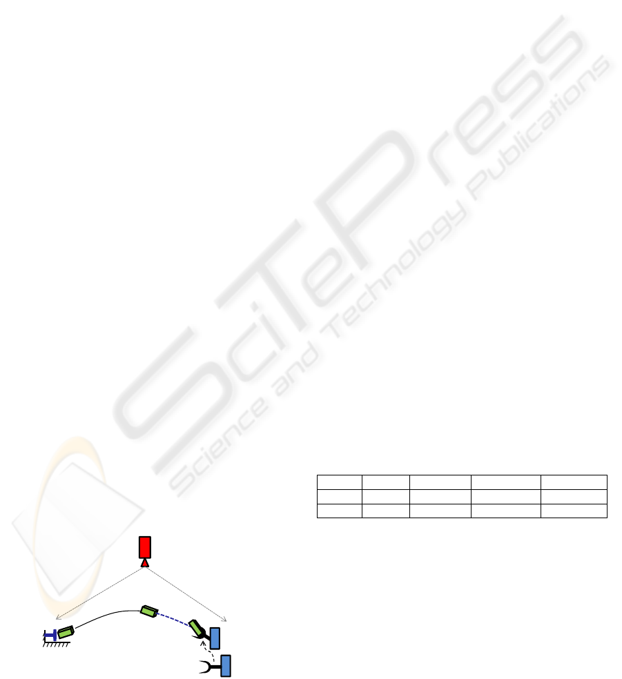
moves to the predicted interception. Figure 1 provides
schematic description of the approach. Scope of this
work is restricted to trajectory measurement.
There are four classes in logistic chains in which
trajectory measurement
trajectory prediction
gripper positioning
throwing
Figure 1: A schematic description of the throw-catch ap-
proach.
the throw-catch approach can be realized (Frank et al.,
2009). Table 1 summarizes these. So far feasibil-
ity of the approach is tested with spherical objects
in fact tennis ball (Barteit et al., 2009). Objects of
different nature behave aerodynamically differently.
Their appearance also varies. Among these spheri-
cal objects are least vulnerable to change their trajec-
tory, appearance, and grasping. Non-spherical objects
change their view and hence project differently on im-
age plane. A change in their view results into a change
in their area across airstream that changes its aero-
dynamic behavior. Moreover, grasping of the object
would also need its orientation information. There-
fore, task of trajectory measurements in that case be-
comes task of pose tracking.
Table 1: Classification of throwing tasks and objects.
Object workpiece packaging assembly food
Shape ball cuboid axial symmetric irregular
Function sorting transportation separation commissioning
Work done so far in the throw-catch approach
is not only based on simplified nature of object but
also the environment. While trajectory measurement,
background is supposed to be static, a high contrast
between object and background is set, and diffused
lighting is assumed. This is contradiction to the
claim of flexible transportation. In production envi-
ronments, pose tracking may present challenging sit-
uations. The first is dynamic background. This is due
to a number of activities going on in parallel. These
include staff movement, motion of assembly units and
316
Akhter N. (2012).
TRACKING PLANAR-TEXTURED OBJECTS - On the Way to Transport Objects in Packaging Industry by Throwing and Catching.
In Proceedings of the 1st International Conference on Pattern Recognition Applications and Methods, pages 316-321
DOI: 10.5220/0003731503160321
Copyright
c
SciTePress

accessories, displacement of tools, chairs, tables etc.,
and objects of multirouting. The second is appearance
of object and background may change. A new ap-
pearance may be introduced. Maintaining high con-
trast and constraint of diffused light impose unneces-
sary conditions. The third is object can be partially
occluded. This could be due to moving entities of
the scene, on the way object may partially leave field
of view, or illumination may blur part of the object.
Finally, interframe displacement may be large. This
could be due to high speed of object, low temporal
resolution of camera, or frame drop.
Indeed, flexibility not only depends on overcom-
ing the challenging situations but also on adaptivity to
change in object and background nature. This can be
achieved by decoupling foreground from background.
An approach that provides 6-DoF pose without offline
learning and/or image segmentation becomes impor-
tant. Rather than independently performing object de-
tection and pose estimation, integration of these tasks
may reduce computational cost. A single camera and
exploiting minimum structural detail of object may
reduce information density. In brief, objective of this
research is not only to handle challenges of tracking
in industry, but also to make the throw-catch approach
flexible in real sense. Scope of the work is restricted
to packaging industry. Packaging objects are labeled
with text and graphics such as product information,
brand name, brand logo etc. Therefore, it is reason-
able to assume they have sufficient texture.
Rest of the paper is divided into four sections.
Section 2 reviews state of the art in pose tracking,
based on the outcome, a hybrid approach is presented
in Section 3. Evaluation of the approach is described
in Section 4. Finally, Section 5 concludes the paper.
2 POSE TRACKING
On a broad level, approaches of pose tracking
for textured-planar targets can be divided into two
groups: pose tracking by detection and pose track-
ing by modeling. The first type of approaches (Bjork-
man and Kragic, 2004; Ekvall et al., 2005; Lepetit
et al., 2004) build 2D-3D mapping using training data
consisting of several views of the target. The con-
structed mapping is then used to find pose of a given
2D target image, which makes them rigid to learned
scenarios. Scenes in which targets are easy to de-
tect are assumed (Azad, 2009). Although suitable for
large interframe displacement as strong prior on the
pose is not required, they are less accurate and more
computationally intensive than the second type of ap-
proaches (Lepetit and Fua, 2005).
The second type of approaches pre-assumes a 3D
model of target. They require a strong prior on the
pose to iteratively evolve to actual pose. Typically,
they recover pose by first establishing 2-3D feature
correspondence and then solving for the pose using
a pose estimation technique. Based on the type of
feature, they are further divided into template based
and keypoint based approaches. Template based ap-
proaches (Mei et al., 2008; Baker and Matthews,
2004; Jurie and Dhome, 2002) estimate pose of a
reference template by minimizing an error measure
based on image brightness. In general, they work
under diffused lighting, no occlusion, and small in-
terframe displacement (Ladikos et al., 2009; Lepetit
and Fua, 2005). Keypoint based approaches (Ladikos
et al., 2009; Vacchetti et al., 2004b; Collet et al.,
2009) exploit local appearance of targets. They work
opposite to template based approaches but relatively
computationally expensive (Lepetit and Fua, 2005).
As they require sophisticated feature model of com-
plete object, they are less flexible to adapt new ob-
ject. A common problem with the second type of ap-
proaches is pose drift due to error accumulation over
long sequences (Lepetit and Fua, 2005).
Approaches (Choi and Christensen, 2010;
Ladikos et al., 2009; Rosten and Drummond, 2005;
Vacchetti et al., 2004a) also exist that combine
more than one type of approaches with intention to
increase accuracy and/or achieve robustness. There is
none that simultaneously addresses large interframe
displacement and flexibility to adapt change in scene.
Moreover, rather than fusing they work either by
feeding output of one approach to second approach
or by switching between the two approaches. The
proposed approach intrinsically assimilate template
based and keypoint based tracking due to their
complementary role in achieving the goal. In con-
trast to estimate pose from pre-learned samples,
deformation in the template is used. In place of
intensity, point based error measure is defined to
find the deformation. Tasks of detection and pose
estimation are performed simultaneously without
imposing constraints on background. The approach
intrinsically delays pose drift.
3 FUSING POINT AND
TEMPLATE INFORMATION
To fuse point information into template, template
based tracking introduced by Mei et al. (Mei et al.,
2008) is chosen. This is for its high accuracy and bet-
ter convergence. Pseudocode of the algorithm with
point information incorporated is given in figure 2.
TRACKING PLANAR-TEXTURED OBJECTS - On the Way to Transport Objects in Packaging Industry by Throwing
and Catching
317

Let I
1
be a reference image of a monocular se-
quence I
k
, k = 1...K, such that a region I
re f
(refer-
ence patch) of this contains projection of the planar
target. Given an approximate transformation
˜
T con-
sisting of rigid motion (rotation
˜
R, translation
˜
t) in
terms of camera motion, features F
re f
extracted from
I
re f
, and a set of thresholds, the algorithm returns the
actual T . Theoretically, it is equivalent to map I
re f
to
desired region defined by T in the current image I
k
that minimizes sum of square distance (SSD) over all
feature points.
Input:I1,Iref,Ik,Fref,,thresholds(maxIter,num,err)
Output:T
T
~
Iter = 0
While(iter < maxIter)
Compute ,
H = + nd
’
Icur = definePatch(Ik,Iref,H)
Fcur = extractFeatures(Icur)
R
~
t
~
R
~
t
~
matches = matchFeatures
(
F
ref
,
Fcur
)
removeOutliers(matches)
x = -2J
+
D(0)
if ||x|| < err
T =
break
else
T
~
else
= T(x)
end
end
T
~
T
~
Figure 2: Pseudocode of the ESM algorithm fused with
point information.
Algorithm starts by computing transformation of
the target in image plane using homography H asso-
ciated to
˜
T . Such that
˜
T =
˜
R
˜
t
0 1
(1)
H = (
˜
R +
˜
tn
0
d
) (2)
p = π(w(H(
˜
T )))π
−1
(p
∗
) (3)
where n
d
is a vector defined as
n
d
consisting of nor-
mal n and distance d of the target plane from cam-
era. w is a warping function that defines a coordinate
transformation between points on a unit plane (nor-
malized plane). π is a projection function that de-
fines projection of a point on the unit plane to im-
age plane. Practically, this is to find the new position
p in the current image of a pixel p
∗
in the reference
image. With this a patch I
cur
(current patch) in the
current image is defined. This leads to four benefits.
One region to search the target in image is confined.
Second explicit detection or segmentation of the tar-
get is avoided which saves computation on run time.
Third likelihood of correspondence with background
is reduced. Fourth background is intrinsically ignored
which in turn makes background dynamics irrelevant.
In the next step features F
cur
are extracted from the
defined patch. The Scale Invariant Feature Transform
(SIFT) is an approach for extracting local features that
are reasonably invariant to scaling, translation, rota-
tion, illumination changes, image noise, affine distor-
tion, occlusion, and viewpoint change (Sangle et al.,
2011). Further motivation comes from its use in real-
time tracking on mobile phones (Wagner et al., 2008).
Therefore, this work uses SIFT. Extracted features are
then matched with the F
re f
using K-d tree. False
correspondence is avoided by first removing points
with multiple correspondences. Then further remov-
ing whose Euclidian distance and slope exceeds a spe-
cific range. Based on the number of features, empir-
ically determined two strategies are employed. If the
number exceeds 40, Gaussian distribution is assumed
and the range is defined by equation 4. Otherwise, it
is defined by equation 5.
Mean {slope, distance} ±1.5 × its Standard deviation (4)
Median {slope, distance} ±0.66 × Median {slope, distance} (5)
Once outliers are removed, cost of matching is
then computed between the corresponding points. Let
the corresponding points are {l
i, j
} and {m
i, j
} in the
reference and current patches respectively. Let D
q
be
the distance between q
th
pair of corresponding points,
the cost is defined as:
∀i ∈ 1, 2, ..., q D
i
= l
i
− m
i
(6)
If the SSD value of vector D approaches to zero,
the estimated pose becomes equal to the actual pose.
Tracking jumps to the next image. Otherwise, there
is a need to update
˜
T . Let the update is denoted by
T (x). Where x is a parameter vector that consists of
coefficients of base elements: three for translation B
1
-
B
3
and three for rotation B
4
-B
6
such that
T (x) = exp(
6
∑
i=1
x
i
B
i
) (7)
B
1
=
"
0 0 0 1
0 0 0 0
0 0 0 0
0 0 0 0
#
B
4
=
"
0 0 0 0
0 0 −1 0
0 1 0 0
0 0 0 0
#
B
2
=
"
0 0 0 0
0 0 0 1
0 0 0 0
0 0 0 0
#
B
5
=
"
0 0 1 0
0 0 0 0
−1 0 0 0
0 0 0 0
#
(8)
B
3
=
"
0 0 0 0
0 0 0 0
0 0 0 1
0 0 0 0
#
B
6
=
"
0 −1 0 0
1 0 0 0
0 0 0 0
0 0 0 0
#
More precisely, the problem of pose estimation is
to minimize the cost of matching which in terms of
the parameter vector can be described as
∀i ∈ 1, 2, ..., q D
i
(x) = π(w(H(T (x)
˜
T )))π
−1
(l
i
) − m
i
(9)
ICPRAM 2012 - International Conference on Pattern Recognition Applications and Methods
318
Minimizing this expression is a nonlinear optimiza-
tion task. Let cost function D(x) be the vector
[D
1
(x) D
2
(x) D
3
(x) ... D
q
(x)]
0
that corresponds to the
distance over all points at the given parameter vec-
tor x. By the second order approximation of D(x)
about x = 0 using Taylor series and simplification
(Mei et al., 2008)
D(x) ≈ D(0) +
1
2
Jx (10)
J = J
π
J
w
J
H
J
T
(11)
where J is jacobian of the D with respect to the x. In
contrast to the original Jacobian which is composed of
jacobians of each of image J
I
, image projection func-
tion J
π
, image warping function J
w
, homography J
H
,
and transformation J
T
. In this work, it is composed
of the other four except J
I
. This is to reduce non-
linearity in the cost function. In the former case there
are two factors that introduce non-linearity in the cost
function. First corresponds to non-linear projection
and second corresponds to intensity information. In
fact pixel values are essentially un-related to pixel co-
ordinates (Baker and Matthews, 2004), therefore, J
I
is ignored. This allows using fewer details, regions
in spite of the complete reference patch. Moreover,
impact of non-linearity should be reduced as the cost
function is better defined. Outcome of testing with
simulated sequence confirms this. Expression of each
of the jacobian for each feature point l
i
normalized to
the unit plane is
J
π
= ∇
P
π(P)|
P=l
i
(12)
J
w
= ∇
H
(w(H))(P)|
H=H(0)=I
(13)
J
H
= ∇
T
H(
˜
T )
−1
H(T
˜
T )|
T =T(0)=I
(14)
J
T
= ∇
x
T (x)|
x=0
(15)
Solution to the problem lies in finding a param-
eter vector x
0
such that D(x
0
) = 0. This is obtained
by iteratively solving the cost function such that for a
vector x = x
0
∇D(x)|
x=x
0
= 0 (16)
At each iteration an updated x is calculated as follows
x = −2J
+
D(0) (17)
where D(0) is the cost at x = 0, and J
+
means
pseudo-inverse of J. Once convergence (kxk < err) is
achieved in the current image, the optimal transforma-
tion T
k
between the reference I
1
and the current image
I
k
is obtained. The algorithms finishes with this image
and restarts with the next image I
k+1
. Let T
k
(x
0
) be
the relative transformation between the last two con-
secutive frames I
k−1
and I
k
. Pose estimation starts in
the next image with the following approximation
˜
T (k +1) = T
k
(x
0
)T
k
(18)
Tracking continues till the last image I
K
is reached
and a total transformation T
K
without pose drift is
found.
4 RESULTS AND DISCUSSION
Evaluation of the proposed approach is made using
both the simulated and real sequences. In the first
case, it is made with reference to the Mei et al. using
the same simulated sequence on which the referenced
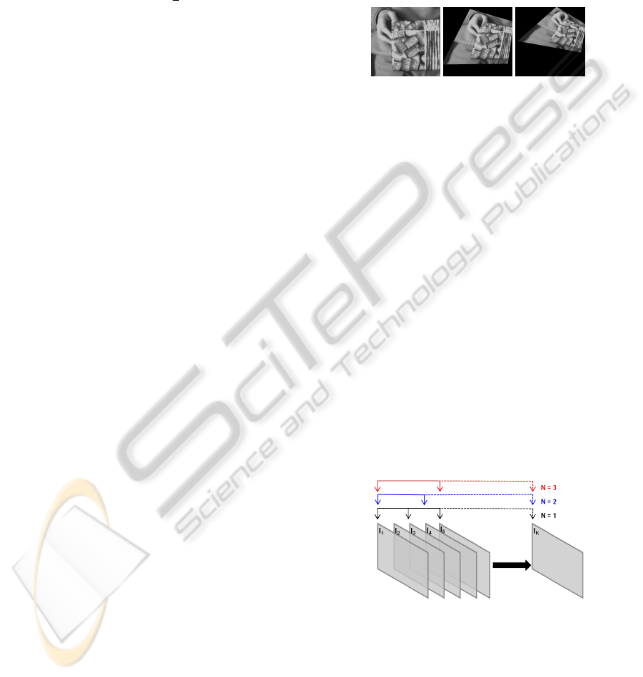
approach was tested. Figure 3 shows three images of
the simulated sequence.
Figure 3: Images 1, 50, and 100 respectively in the simu-
lated sequence.
Figure 5 shows how do the two approaches be-
have on average bases, in terms of absolute transla-
tional error, absolute rotational error, and number of
iterations elapsed to converge, with the increase in in-
terframe displacement. The interframe displacement
is increased by skipping multiple images at regular
intervals from the original sequence. Started by skip-
ping alternate images and ending with two images in
the sequence. Figure 4 elaborates skipping procedure.
One can see by fusing point information into the pure
template based tracking both the errors remain more
than half below. The errors oscillate in the beginning
for the reason of small baseline effect while stabilizes
later. In the case of number of iterations, although
difference between the two is small in the beginning
but immediately that is after skipping just two images
raises dramatically. The proposed approach showed
consistent behavior. The most considerable fact is
that the referenced approach fails tracking beyond 10
number of images skipped. This is due to its reliance
on strong prior on the pose.
Figure 4: Three instances of skipping alternate images. N
corresponds to the number of images skipped. Arrow points
to the selected image.
In the second case, the approach is tested with real
sequences. These sequences consist of flight of ten
cubical objects thrown horizontally across the princi-
pal axis of camera. For each object 50 sequences are
collected. They are thrown at a distance of 1.6
±0.45
m from camera with their largest plane exposed to the
TRACKING PLANAR-TEXTURED OBJECTS - On the Way to Transport Objects in Packaging Industry by Throwing
and Catching
319

0 5 10 15 20 25 30 35
0.5
1
1.5
2
2.5
3
number of images skipped
abs. translation error (mm)
← ~failed
proposed
referenced
0 5 10 15 20 25 30 35
0.5
1
1.5
2
2.5
3
number of images skipped
abs. rotational error (mrad)
← ~failed
proposed
referenced
0 5 10 15 20 25 30 35
0
5
10
15
20
25
30
number of images skipped
number of iterations
← ~failed
proposed
referenced
Figure 5: Comparison based on interframe displacement.
camera. Figure 6 shows the planes. Their sizes and
number of features extracted from each plane at this
distance are given in Table 2. Horizontal field of view
at this distance is 1.2 m. Before leaving field of view,
they lie at 1.44±0.45 and 0.07±0.21 m from camera
along Z and Y axis respectively. Another calibrated
camera is used to find the distances and normal to the
plane using stereo vision. The range of estimated ro-
tation along each of the X, Y, and Z axis is -37.93 to
35.08, -30.50 to 50.90, and -15.50 to 44.68 degrees
respectively.
Figure 6: Planes of the objects and their assigned names.
Top to bottom followed by left to right: (a) Daisy, (b) Gar-
ment, (c) Donuts, (d) Monster, (e) Rice, (f) Chicken, (g)
China, (h) Biscuit, (i) Juice, (j) and Bravo.
Evaluation is made using the methodology intro-
duced in (Lieberknecht et al., 2010). Tracking error is
defined as root mean square (RMS) distance between
estimated corner p of the plane and its ground truth
p
∗
which is generated manually. Such that
Table 2: Sizes and feature amount of the planes.
Plane Number of features Size (mm × mm)
Daisy 155 300 × 160
Garment 177
Donuts 99 285 × 120
Monster 130
Rice 185 250 × 160
Chicken 114
China 188 200 × 175
Biscuit 107
Juice 69 240 × 115
Bravo 102
tracking error =
v
u
u
t
1
4
4
∑
i=1
kp
i
− p
∗
i
k
2
(19)
Figure 7(a) shows tracking error on average and
extreme bases. For each plane the average is taken
per image over all the 50 throws. One can see the
approach performs equally well in all the cases ex-
cept Juice. This is due its much lower amount of
texture (number of features) relative to the rest. A
common trend among all the planes is that the error
increases with the increase in image number. This is
partially due to error accumulation and partially due
to loss in features. The loss is due to throwing objects
in front of the camera. So in the subsequent frames
fine texture loses. Figure 7(b) shows decrease in fea-
ture amount on average bases with the increase in im-
age number. The interframe displacement was large
enough that in no case the referenced approach is able
to track the plane.
0 5 10 15 20
0
1
2
3
4
5
6
tracking error (px)
image number
Bravo
Chicken
China
Daisy
Donuts
Biscuit
Juice
Garment
Monster
Rice
Minimum
Maximum
0 5 10 15 20
0
50
100
150
200
number of features
image number
Bravo
Chicken
China
Daisy
Donuts
Biscuit
Juice
Garment
Monster
Rice
Figure 7: Testing with real sequences: (a) tracking error, (b)
feature decay.
Sequences are acquired without diffused lighting.
Figure 8 confirms this. Having success with this
shows robustness of the approach against illumination
changes. To further show robustness of the approach
ICPRAM 2012 - International Conference on Pattern Recognition Applications and Methods
320
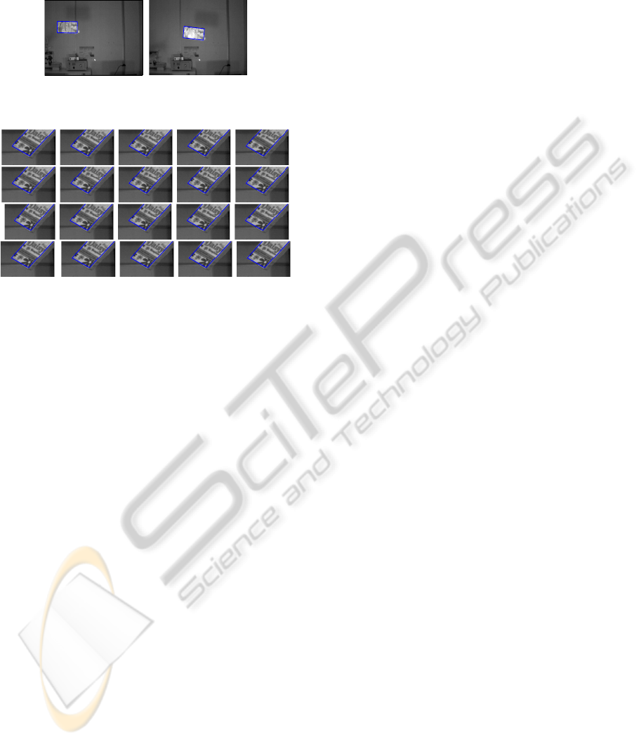
against partial occlusion, Figure 9 presents two in-
stances of tracking under extreme occlusion for each
plane before it leaves field of view.
seq/plane3D0001
seq/plane3D0006
Figure 8: Two images of a sequence in which appearance
of the plane changes due to non-diffused lighting.
Figure 9: Two instances of tracking each plane under ex-
treme occlusion. Top to bottom followed by left to right:
(a) Daisy, (b) Donuts, (c) Rice, (d) China, (e) Juice, (f) Gar-
ment, (g) Monster, (h) Chicken, (i) Biscuit, (j) and Bravo.
5 CONCLUSIONS
A hybrid approach by fusing point and template based
tracking to track planar-textured targets with large in-
terframe displacement is introduced. The approach is
flexible to adapt change in scene. It makes an effi-
cient use of object and scene detail. Its evaluation is
made using both the simulated and real sequences. In
the first case, the approach performs better in terms
of accuracy, convergence, and interframe displace-
ment. In the second case, a consistent behavior is seen
with the change in target. Robustness of the approach
against partial occlusion and illumination changes is
also shown. One may argue the approach is compu-
tationally expensive in terms of feature employed. To
compensate this, a part of image is exploited. More-
over, faster convergence further weakens the argu-
ment, particularly, when the interframe displacement
is large. At the application level, scope of trajectory
measurement is extended to packaging industry con-
sidering industrial environment.
REFERENCES
Azad, P. (2009). State of the art in object recognition and
pose estimation. Cognitive Systems Monographs: Vi-
sual Perception for Manipulation and Imitation in Hu-
manoid Robots.
Baker, S. and Matthews, I. (2004). Lucas-kanade 20 years
on: A unifying framework. IJCV.
Barteit, D., Frank, H., Pongratz, M., and Kupzog, F. (2009).
Measuring the intersection of a thrown object with a
vertical plane. In IEEE INDIN.
Bjorkman, M. and Kragic, D. (2004). Combination of
foveal and peripheral vision for object recognition and
pose estimation. In IEEE ICRA.
Choi, C. and Christensen, H. I. (2010). Real-time 3d model-
based tracking using edge and keypoint features for
robotic manipulation. In IEEE ICRA.
Collet, A., Berenson, D., Srinivasa, S. S., and Ferguson, D.
(2009). Object recognition and full pose registration
from a single image for robotic manipulation. In IEEE
ICRA.
Ekvall, S., Kragic, D., and Hoffmann, F. (2005). Object
recognition and pose estimation using color cooccur-
rence histograms and geometric modeling. Image and
Vision Computing.
Frank, H., Barteit, D., and Kupzog, F. (2008). Throwing or
shooting - a new technology for logistic chains within
production systems. In IEEE TePRA.
Frank, H., Mittnacht, A., and Scheiermann, J. (2009).
Throwing of cylinder-shaped objects. In IEEE/ASME
AIM.
Jurie, F. and Dhome, M. (2002). Hyperplane approximation
for template matching. IEEE TPAMI.
Ladikos, A., Benhimane, S., and Navab, N. (2009). High
performance model-based object detection and track-
ing. incollection-Theory and Applications: Computer
Vision and Computer Graphics.
Lepetit, V. and Fua, P. (2005). Monocular model-based 3d
tracking of rigid objects. FTCGV.
Lepetit, V., Pilet, J., and Fua, P. (2004). Point matching as a
classification problem for fast and robust object pose
estimation. In IEEE CVPR.
Lieberknecht, S., Benhimane, S., Meier, P., and Navab, N.
(2010). Benchmarking template-based tracking algo-
rithms. Virtual Reality.
Mei, C., Benhimane, S., Malis, E., and Rives, P. (2008).
Efficient homography-based tracking and 3-d recon-
struction for single-viewpoint sensors. IEEE TRO.
Rosten, E. and Drummond, T. (2005). Fusing points and
lines for high performance tracking. In IEEE ICCV.
Sangle, P., Kutty, K., and Patil, A. (2011). A method for
generation of panoramic view based on images ac-
quired by a moving camera. IJCA.
Vacchetti, L., Lepetit, V., and Fua, P. (2004a). Combining
edge and texture information for real-time accurate 3d
camera tracking. In IEEE/ACM ISMAR.
Vacchetti, L., Lepetit, V., and Fua, P. (2004b). Stable real-
time 3d tracking using online and offline information.
IEEE TPAMI.
Wagner, D., Reitmayr, G., Mulloni, A., Drummond, T., and
Schmalstieg, D. (2008). Pose tracking from natural
features on mobile phones. In IEEE/ACM ISMAR.
TRACKING PLANAR-TEXTURED OBJECTS - On the Way to Transport Objects in Packaging Industry by Throwing
and Catching
321
