
APPLICATION OF A GTEM CELL TO DETERMINE RF INDUCED
CURRENTS IN ELECTRODES OF MEDICAL IMPLANTS
An Alternative to Measurements in MRI Birdcages
Karin M
¨
ortlbauer, Daniel Zemann and Erwin Hochmair
Institute of Ion Physics and Applied Physics, University of Innsbruck, Technikerstrasse 25, 6020 Innsbruck, Austria
Keywords:
VNA, GTEM cell, Transmission line, Scattering parameter, Medical-Implant, MRI.
Abstract:
RF induced currents in elongated electrodes of medical implants can cause hazardous tissue heating during
MRI scans. In this paper we introduce an experimental setup to investigate the influence of the geometri-
cal electrode design on the magnitude of the RF induced current. A Vector Network Analyser (VNA) was
connected to a Gigahertz Transverse Electromagnetic (GTEM) cell containing the electrode under test. The
forward power gain (S
21
scattering parameter) was measured by the VNA, whereof the magnitude of the cur-
rent at the electrode tip could be derived. Furthermore, calculations via transmission line theory were done
to describe the present mechanism of current induction. These calculations show good agreement with the
results of the performed measurements.
1 INTRODUCTION
Medical implants used to electrically stimulate nerves
or muscles (e.g. cardiac pacemakers, cochlear im-
plants or deep brain stimulation) find widespread ap-
plication in therapeutic medicine. Some of these im-
plants are contraindicated with magnetic resonance
imaging (MRI). If these implants contain compara-
tively long metallic electrode leads, these electrodes
couple with the radiofrequency field of the MRI scan-
ner, which can cause serious burns of tissue specif-
ically in the vicinity of the electrode contacts (Nitz
et al., 2001). A current is induced along the axis of
the electrode lead, which is prone to create a high cur-
rent density in the tissue at the electrode contact. The
electrical energy is absorbed and converted into ther-
mal energy in the tissue, which has a much higher
specific ohmic resistance than the electrode material.
Therefore the amount of heating depends on the in-
duced current, which in turn depends on the geo-
metric design of the electrode. Other authors have,
for instance, investigated tissue heating of different
solenoidal electrode designs (Gray et al., 2005). Such
changes in the electrode geometry may be capable of
avoiding hazardous tissue heating.
In this paper we present an experimental setup to
investigate the influence of electrode design on tis-
sue heating. Instead of a temperature measurement of
the tissue in a MRI birdcage, however, measurements
of scattering parameters were performed by a Vector
Network Analyser (VNA), connected to a Gigahertz
Transverse Electromagnetic (GTEM) cell containing
the electrode.
It is important to mention that the exciting elec-
tromagnetic field in the GTEM cell differs from the
one in the MRI birdcage. Therefore, the presented
GTEM setup is not proper for safety measurements
of certain electrodes, but allows comparative investi-
gations of induced RF currents in differently designed
electrodes.
2 METHOD
The different electrode geometries were investigated
under two different circumstances: with an alignment
of the electrode perpendicular to the electric field and
parallel to it. The experimental setup and the trans-
mission line theory for the former alignment are de-
scribed in the following paragraphs. The latter situa-
tion, which is more realistic in comparison to the sit-
uation in the MRI birdcage, will be subject of future
experiments.
2.1 Experimental Setup
A LA19-13-02 3GHz VNA (LA Techniques, UK)
315
Mörtlbauer K., Zemann D. and Hochmair E..
APPLICATION OF A GTEM CELL TO DETERMINE RF INDUCED CURRENTS IN ELECTRODES OF MEDICAL IMPLANTS - An Alternative to
Measurements in MRI Birdcages.
DOI: 10.5220/0003763103150318
In Proceedings of the International Conference on Biomedical Electronics and Devices (BIODEVICES-2012), pages 315-318
ISBN: 978-989-8425-91-1
Copyright
c
2012 SCITEPRESS (Science and Technology Publications, Lda.)
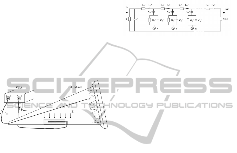
was connected to a GTEM cell (Model 5402, ETS-
Lindgren, USA) as it is shown in Figure 1. The
output power of the VNA from port 1 was used to
generate a homogeneous transverse electromagnetic
field inside the GTEM cell. The electrode was posi-
tioned inside a medium and connected to port 2 via a
BNC-connector at one end and left in contact to the
medium on the other end. Several different media
were investigated: air, silicone and a phantom mus-
cle. The latter was a mixture of the gelling agent
TX151 (Brunschwig Chemie, Netherlands), distilled
water and sodium chloride (Chou et al., 1995). The
electrode axis was in a horizontal orientation and thus
perpendicular to the electric field, which is vertically
aligned. The electric field was measured with an elec-
tric field probe (D.A.R.E.!! Instruments, RadiSense,
LP1001A, Netherlands).
Figure 1: Connection of the VNA and the GTEM cell.
The electrode under test is horizontally positioned and sur-
rounded by a medium.
The Network Analyser measures the amplitude
and phase of the four scattering parameters in a fre-
quency range from 3 MHz to 300 MHz. Only the
reverse (S
12
) or forward (S
21
) power gain – both are
equal (reciprocity theorem) – are relevant in our in-
vestigation. The S
21
-parameter is defined as the ratio
of the transmitted power at the matched port 2 to the
input power at port 1. We compared the amplitudes
of the S
21
-parameter of different electrode geometries
(straight wires, completely and partially solenoidal
wires) over the complete frequency range in air and
silicone and at 64 MHz and 128 MHz in the phantom
material, which are the RF frequencies for the 1.5 T
and 3 T MRI-scanners, respectively.
The electrodes tested in viscous materials (e.g. sil-
icone) were moulded into these materials to provide a
perfect contact between the tip of the electrode and
the medium.
2.2 Transmission Line Theory
A part of the equivalent circuit of the electrode be-
ing excited by the electric field of the GTEM cell is
shown in figure 2. It is important to note that a the-
oretical description of the electrode as a transmission
line must include environmental parameters in addi-
tion to intrinsic parameters of the electrode (Konings
et al., 2000). In the presented setup, the electrode is
Figure 2: The equivalent circuit of the electrode in a per-
pendicular electric field inside the GTEM cell.
considered to be the inner conductor and the housing
of the GTEM cell the outer conductor of the trans-
mission line. The field perpendicular to the electrode
axis induces a voltage u between the electrode and
the GTEM housing. The equivalent circuit is a cas-
cade connection of n consecutive quadripoles (three
of them are shown in figure 2). Each quadripole
is characterized by two complex impedances, one
along the wire, consisting of a resistance R
0
w
in se-
ries with an inductance L
0
w
, another between the in-
ner and outer conductor, consisting of C
0
w
in series
with a parallel connection of G
0
m
and C
0
m
. R
0
w
and
L
0
w
are the resistance and inductance of the wire per
quadripole length, respectively, C
0
w
is the capacitance
along the insulation layer between wire and medium
per quadripole length, G
0
m
and C
0
m
are the conductance
and capacitance between the surface of the insulation
and the outer conductor per quadripole length. R
BNC
is the resistance of the BNC-connection (=50Ω). For
simplicity, the lead tip is described as a hemisphere,
with surface area of the lead tip’s real contact area,
and thus representing the capacitance C of a hemi-
sphere and an analogous resistance R. The total resis-
tance and capacitance of the wire were also calculated
by geometric considerations and checked by low fre-
quency measurements and then divided by the num-
ber of quadripoles to yield the values per quadripole
length. A calculation of R
0
w
and C
0
w
is trivial for any
wire with concentric insulation. L
0
w
was estimated via
well known inductance formulas for solenoids and
straight wires. To determine G
0
m
and C
0
m
we consid-
ered the transmission line to be a coaxial line, with the
radius of the outer conductor being equal to the dis-
tance between electrode and cell housing, while the
radius of the inner conductor is equal to the wire ra-
dius for straight wires and equal to the coil radius for
solenoid wires.
The equivalent circuit is a linear network with n
voltage sources and described by 3n+2 independent
first-order differential equations. They can be written
in state space representation:
BIODEVICES 2012 - International Conference on Biomedical Electronics and Devices
316
˙x(t) = A · x(t) + B · u(t), (1)
where A and x(t) are the state matrix and state vector,
B and u(t) are the source matrix and source vector, re-
spectively. In the case of harmonic time dependence
e
jωt
, the equation simplifies such that x(t) can be eas-
ily calculated from u(t) within parts of a second using
a commercial mathematical tool even for networks of
40 quadripoles and more. The vector x(t) contains the
current and voltage along every element of the equiv-
alent circuit including I
BNC
. The power absorbed in
R
BNC
is P
trans
= I
2
BNC
· R
BNC
. The amplitude of the
S
21
-parameter is then given by:
|S
21
| =
p
P
trans
/P
in
, (2)
where P
in
= 1mW .
For in vivo experiments the amount of tissue heat-
ing is most appropriately characterized by the specific
absorption rate (SAR) (Yeung and Atalar, 2001). The
SAR value can be derived from the current density by
SAR = J
2
/(ρ · σ), where ρ and σ are the mass density
and electric conductivity of the tissue, respectively. In
our model the current density is maximal at the elec-
trode contact, where it is equal to I
R
divided by the
area of the electrode contact.
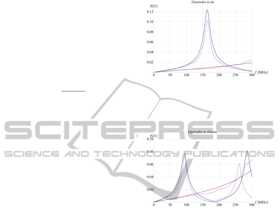
3 PRELIMINARY RESULTS
The model was checked by a rough comparison over
the whole frequency range of measured and calcu-
lated S
21
-parameters of solenoidal and straight cop-
per wires with a diameter of 0.77mm. Figures 3 and
4 show good qualitative agreement of measurement
and calculation of these electrodes in media with dif-
ferent relative permittivity ε
r
, which was air (ε
r
= 1)
and silicone (ε
r
= 3), respectively. A comparison of
our model and a measurement of the electrode in the
phantom muscle were not yet possible; a better defi-
nition of the relative permittivity and conductivity of
the phantom material over the whole frequency range
is required.
Excessive heating effects at the electrode contacts
occur due to resonating RF waves (Konings et al.,
2000), which depend strongly on the length of an
electrode and the surrounding medium. The latter
makes it difficult to exactly predict resonances, which
is important for MRI safety aspects, however.
4 DISCUSSION & OUTLOOK
The presented experimental setup provides a possibil-
ity to determine currents induced in electrodes by RF
Figure 3: Comparison of the amplitude of the measured
(dashed lines) and calculated (solid lines) S
21
-parameter of
a solenoid (blue) and a straight wire (magenta) in air. The
parameters of the solenoid were: #turns = 54, pitch = 2mm,
solenoid radius = 2.5mm, length of the solenoid = 0.1m.
The length of the straight wire also was 0.1m.
Figure 4: Comparison of the amplitude of the measured
(dashed lines) and calculated (solid lines) S
21
-parameter of
a solenoid (blue) and a straight wire (magenta) in silicone.
The parameters of the solenoid and the straight wire were
the same as in figure 3.
fields. It measures the power received by the elec-
trode, which represents an antenna, and verifies the
validity of the equivalent circuit by comparison of the
S
21
-parameter over a wide frequency range. The cur-
rent along the electrode as well as the current density
at the electrode tip (which is relevant for SAR and
thus the temperature rise estimation) can be derived
by a state space analysis of the equivalent circuit. It
has not escaped our attention that this approach con-
tains uncertainties. The correct determination of the
induced currents relies strongly on the accuracy of a
theoretically derived equivalent circuit. Furthermore,
the equivalent circuit correctly describing the situa-
tion of the electrode in the MRI birdcage differs from
the one in the GTEM cell. Thus it is questionable
to what extent one can conclude from the results in
the presented setup to tissue heating in a MRI bird-
cage. The validity of such a conclusion must be con-
firmed experimentally and theoretically. This can be
APPLICATION OF A GTEM CELL TO DETERMINE RF INDUCED CURRENTS IN ELECTRODES OF MEDICAL
IMPLANTS - An Alternative to Measurements in MRI Birdcages
317

achieved by comparing results of our setup to results
of temperature measurements in a MRI birdcage or
verifying the equivalent circuit via numerical com-
puter simulation techniques. This will be a future
challenge.
Nevertheless, already at the present stage the setup
allows fast and uncomplicated measurements over a
wide frequency range including several RF frequen-
cies of present commercial MRI scanners. Such a
broadband current measurement allows a better in-
sight in the mechanism of RF induced currents in
electrodes than temperature measurements at a single
frequency in MRI scanners.
Further work will be done to investigate differ-
ent electrode geometries and materials with electrode
axis parallel to the electric field.
ACKNOWLEDGEMENTS
This research has been supported by MED-EL corp.
in Innsbruck, Austria.
REFERENCES
Chou, C. K., McDougall, J. A., and Chan, K. W. (1995).
Absence of radiofrequency heating from auditory im-
plants during magnetic resonance imaging. Bioelec-
tromagnetics, 16(5):307–316.
Gray, R. W., Bibens, W. T., and Shellock, F. G. (2005).
Simple design changes to wires to substantially re-
duce MRI-induced heating at 1.5 T: implications
for implanted leads. Magnetic Resonance Imaging,
23(8):887–891.
Konings, M. K., Bartels, L. W., Smits, H. F., and Bakker, C.
J. G. (2000). Heating around intravascular guidewires
by resonating RF waves. Journal of Magnetic Reso-
nance Imaging, 12(1):79–85.
Nitz, W. R., Oppelt, A., Renz, W., Manke, C., Lenhart, M.,
and Link, J. (2001). On the heating of linear conduc-
tive structures as guide wires and catheters in interven-
tional MRI. Journal of Magnetic Resonance Imaging,
13(1):105–114.
Yeung, C. J. and Atalar, E. (2001). A green’s function ap-
proach to local rf heating in interventional MRI. Med-
ical Physics, 28(5):826–832.
BIODEVICES 2012 - International Conference on Biomedical Electronics and Devices
318
