
A MAGNETIC COUPLING TO IMPROVE
PLACEMENT OF GASTROENTERAL FEEDING TUBES
David Cronin, Tadhg Lambe
and Pádraig Cantillon-Murphy
School of Engineering, University College Cork, Cork, Ireland
Keywords: Permanent Magnets, Endoscopy, Gastroenteral Feeding Tube, PEG, Magnetic Coupling.
Abstract: Percutaneous Endoscopic Gastrostomy (PEG) is a non operative endoscopic technique to place a
transabdominal (from outside the abdomen through the gastric wall and into the stomach) gastric feeding
tube. It is the preferred method of eneteral feeding in patients who would otherwise have inadequate
nutritional intake due to a number of underlying illnesses. During the PEG procedure, the feeding tube can
deviate from its intended path, perforate organs and surrounding tissues leading to complications. We
propose a novel technique to alleviate or eliminate these concerns using magnetic coupling. This technique
forces the tube to pass through a specified path, compressing tissues between the gastric and abdominal
walls such that the tube cannot deviate from its intended path. This modified PEG procedure could secure a
safer tract for insertion, decrease procedural time and limit user variability, with hypothesised benefits
including shorter procedural times and lower complication rates. The magnetic coupling mechanism has
been modelled using analytical tools with experimental validation. The approach has been demonstrated in a
bench-top anatomical model and may be of use in applications beyond the PEG procedure including
endoscopic instrument positioning on the gastric wall.
1 INTRODUCTION
1.1 Enteral Nutrition Techniques
Enteral nutrition is a means of delivering nutrition to
patients who would otherwise be unable to feed
themselves for a variety of reasons: neurological
impairment, dysphasia (difficulty in swallowing)
after surgery, oral cavity tumours, anorexia, or as a
preventative for aspiration pneumonia. There are a
number of types of enteral feeding solutions used
but the most common are nasogastric tubes (NGT)
and gastroenteral tubes, placed using the
percutaneous endoscopic gastrostomy (PEG)
technique. While NGT nutrition is often preferred by
radiologists, PEG is the preferred technique amongst
gastroenterologists, endoscopists and surgeons
(Ponsky, 1981) This is because PEG tubes are easier
to tolerate, show better nutritional results and
patients with PEG tubes have higher survival rates
than those with NGT tubes, even when PEG tube
patients are in more advanced stages of illness
(Dwolatzky, 2001).
However, PEG tube placement is not without
complications including gastric perforation, tube
blockage, site infection, PEG tube dislocation and
inadvertent puncture of peripheral organs such as the
colon (Britton, 1997; Conlon 2004; Loser 1998). In
this work, we are particularly interested in
addressing the last of these complications: the
inadvertent puncture of organs that can become
sandwiched in between the gastric and abdominal
walls during the placement of the PEG tube.
Our solution is a simple magnetic coupling (i.e., two
apposing north/south magnetic surfaces) consisting
in two permanently-magnetized rings which are
initially coupled across the gastric and abdominal
walls to provide a safe tract for subsequent passage
of the gastroenteral feeding tube. Since coupling of
the two rings only occurs inside a predeterminable
distance, we hypothesise that this technique could be
used as to improve feeding tube placement using the
PEG technique by eliminating a significant
complication.
1.2 Magnetic Coupling in Surgery
The use of magnets in minimally-invasive
interventions has a long history. The magnetic
retrieval of foreign bodies in the esophagus, stomach
138
Cronin D., Lambe T. and Cantillon-Murphy P..
A MAGNETIC COUPLING TO IMPROVE PLACEMENT OF GASTROENTERAL FEEDING TUBES.
DOI: 10.5220/0003763401380142
In Proceedings of the International Conference on Biomedical Electronics and Devices (BIODEVICES-2012), pages 138-142
ISBN: 978-989-8425-91-1
Copyright
c
2012 SCITEPRESS (Science and Technology Publications, Lda.)
and deodenum was first proposed as early as 1957
(Equen, 1957). More recently, magnetic coupling
has been used for anchoring of magnetic instruments
(Scott 2007), retrieval of stents (Cantillon-Murphy,
2010) and magnetic NGT guidance (Gabriel 2001)
where an external, hand-held magnet guided the
feeding-tube through the esophageal tract to the
subject's duodenum. In this work, we extend that
work to the use of magnetic coupling for providing a
safe tract for transabdominal insertion of an enteral
feeding tube.
1.3 Current PEG Technique
(a)
(b)
(c)
(d)
(e)
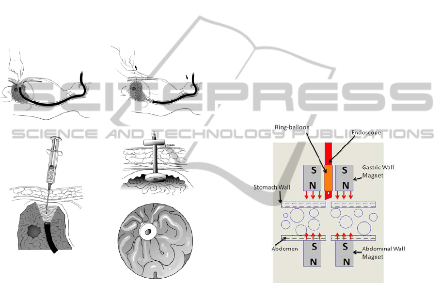
Figure 1: Outline of the current PEG tube placement
procedure involving (a) endoscopic trans-illumination, (b)
transabdominal needle perforation, (c) guidewire-
introduced tube placement, (d) mechanical interlocking
and (e) fixation (reproduced from Ponsky 2004).
Currently, the technique most commonly used for
PEG tube placement is the so-called ‘pull’
technique, outlined in Figure 1. An endoscope is
introduced into the patient’s stomach and a
combination of trans-illumination (i.e., shining the
endoscopic lamp across the gastric and abdominal
walls) and finger pressure is used to determine the
site of closest contact (Figure 1(a)). The so-called
‘safe tract’ method involves insertion of a syringe of
local anaesthetic which is blindly guided across the
abdominal and gastric walls at the site of
transillumination (Figure 1(b)). The site is
catheterised and an endoscopic snare (introduced via
the endoscope’s instrument channel) is used to lasoo
a guidewire which is pushed through the catheterised
abdominal and gastric walls (Figure 1(c)). Removing
the endoscope leaves the guidewire extending across
the abdominal and gastric walls and out of the
patient’s mouth. The guidewire then serves as the
tram-line for the oral introduction of the feeding
tube in advance of reintroducing the endoscope for
inspection. The distal end of the feeding tube usually
has a round bumper to prevent its escape through the
gastrotomy (Figure 1(d, e)). The procedure ends
when the portion of inserted feeding tube outside the
abdominal wall is snipped, the nutrition sack is
attached and the endoscope is removed. The external
t-bar shown in Figure 1(d) sits above the skin and is
designed to stop excessive tension and “buried ring
syndrome” where the gastric wall grows over the
tube thereby causing obstruction
1.4 Magnetic Coupling and PEG
Figure 2: Magnetic coupling to aid in PEG tube
placement.
Our approach is to augment the ‘safe tract’ approach
shown in Figures 1(a) and (b) with a simple
mechanism of temporary magnetic coupling across
the abdominal and gastric walls, as shown in Figure
2. The magnetic coupling of two rings, one on the
abdominal wall (external to the patient) and one on
the gastric wall (endoscopically delivered) is the
second step (i.e., coming between Figures 1(a) and
1(b)) in a slightly modified PEG technique.
However, once the coupling is in place, the result is
that the relative positions of gastric and abdominal
walls are fixed and sandwiched in place at a known
minimum separation, as predicted by theory.
Furthermore, coupling only takes place at a
separation less than a critical maximum which can
A MAGNETIC COUPLING TO IMPROVE PLACEMENT OF GASTROENTERAL FEEDING TUBES
139
be used as a check for inadvertent sandwiching of
organs like the colon between the gastric and
abdominal walls during the procedure.
2 METHODS
2.1 Magnetic Coupling Design
The critical component of the approach is the
coupling of the two magnetic rings at a known and
predictable distance of separation. To investigate,
this dependence, the usual magnetic charge model
was used to simulate magnetic mating of two
permanently magnetised concentric rings (Furlani,
2001). Following the usual Coulombic Law
formulation, the force vector exerted by ‘magnetic
charge’, q
m1
, on ‘magnetic charge’, q
m2
is given by
(1) where μ
0
is the magnetic permeability of free
space (4πx10
-7
H/m) and r
12
is the displacement
vector between q
m1
and q
m2
.
F
12
= μ
0
q
m1
q
m2
/ (4π r
12
2
) (1)
One of the principal challenges in magnetic coupling
is the inverse square roll-off in the force of attraction
between magnetic components. We began by
simulating the coupling forces between concentric
mating magnetic rings using the open-source Radia
(ESRF, France) add-on to Mathematica 7 (Wolfram
Corp., Champaign, Illinois). The magnetic force is
found by discretisation of all the magnetic surfaces
and integration of (1) over the nearby surfaces which
are subject to the field (i.e., the adjacent ring). The
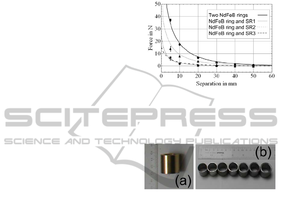
simulated results, shown in Figure 3 demonstrate the
familiar inverse square relation between force and
separation between the two magnetic rings (ignoring
gravitational forces) as well as the force associated
with coupling an external magnet to internal steel
rings (SR1-SR3) of varying dimensions. Based on
the investigations of Figure 3, we designed a
coupling capable of magnetic mating across
expected stomach wall thickness of 3-4 cm. Two
permanent magnetic N52 grade neodymium-iron-
boron (NdFeB) rings were purchased (26mm OD,
18mm ID and 25mm H) from HKCM Engineering,
Germany, for subsequent testing (Figure 4(a)). In
addition, a number of mild steel rings (EN3B grade
mild steel) were fabricated of various wall
thicknesses and lengths (Figure 4(b)). Because
EN3B grade steel has significant paramagnetic
properties (i.e., it behaves magnetically in the
presence of a magnetic field source such as a
permanent magnet with magnetic susceptibility, χ ≈
800), we also investigated the use of mild steel rings
for use as the gastric wall magnet in Figure 2.
Figure 3: Force-separation characteristics between the N52
grade ring magnet and (i) a second identical magnetic ring
(MR), and (ii) three stainless steel rings of varying
thicknesses and lengths; SR1 with 26mm OD, 20mm ID
and 25mm H, SR2 with 26mm OD, 20mm ID and 12.5mm
H and SR3 with 22mm OD, 20mm ID and 12.5mm H.
Gravitational forces are ignored.
Figure 4: The gold-plated N52 grade neodymium-iron-
boron ring (a) and stainless steel rings of various
thicknesses (b) which were used in subsequent testing.
2.2 Mechanical Design
The most significant challenge in implementing a
magnetic coupling across the gastric and abdominal
walls was the placement of the gastric wall magnet
within the patient’s stomach without any incision.
Since the PEG procedure already involves the oral
introduction of an endoscope, we used the
endoscope as the vehicle to carry the gastric magnet
into its final position. A number of approaches were
considered including introducing the magnet in
advance of the endoscope using a magnetised
catheter. However, the technique that was found
most satisfactory was spearing the ring with the
endoscope’s shaft with a radially-inflatable ring
balloon between the endoscope and magnet, as
shown in Figures 5 and 6. This approach had four
significant advantages; (i) the magnet could be held
in position on the endoscope’s shaft by inflation of
the balloon and released for coupling by deflation;
(ii) inflation of the balloon beyond the ring OD
BIODEVICES 2012 - International Conference on Biomedical Electronics and Devices
140
during oral insertion limited any possibility of
tearing to the oesophageal wall upon introduction of
the endoscope; and (iii) the magnet presented no
visual impediment to the scope’s field of view.
The ring balloon was constructed from a 51Fr
(17mm) veterinary endotracheal tube (Jorgensen
Laboratories, Colorado) which was chosen to fit
snugly over a standard 12mm diameter endoscope
(GIF Q20 by Olympus Inc., Japan). The balloon was
lure-lock connected to a standard endovascular
balloon indeflator (Boston Scientific Corp.,
Massachuetts) which was used to inflate the balloon
to a measureable pressure as shown in Figure 5(c).
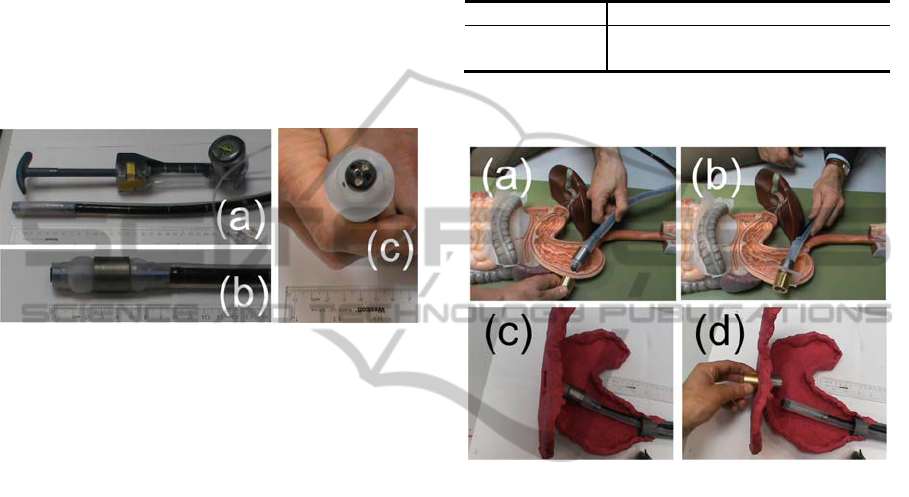
Figure 5: (a) An modified endotraceal tube was used as the
ring balloon, fitting snuggly over the 12mm endoscope.
(b) When inflated, the balloon fixed the ring on the
endoscope’s shaft. (c) The balloon also minimised risk of
tissue tearing due to the magnet’s edges upon insertion of
the endoscope.
3 RESULTS
3.1 Magnetic Coupling
The magnetic coupling force predicted by Figure 3
was experimentally investigated by compression and
separation tests using a Stable Micro Texture
Analyser (Godalming, UK). The resultant force -
separation characteristic for the various rings are
shown as datapoints on Figure 3.
To accurately predict the required force to couple
the gastric and abdominal magnets in the presence of
the inflated balloon, the axial force required to slide
the gastric magnet off the inflated balloon was also
investigated as a function of various balloon
inflation pressures. This is an important parameter
because, in the modified procedure, the magnetic
coupling is mainly impeded by the frictional forces
between the balloon and gastric magnet, which
varies as a function of inflation pressure, and not
gravitational force The coupling distance (i.e.,
critical distance at which mating occurs) between the
various gastric magnets of Figure 3 and the NdFeB
abdominal ring magnet is shown in Table 1. These
results correspond to the worst-case scenario where
gravity acts axially against the magnetic coupling
force. This is not unrealistic in a clinical setting
where the PEG placement usually takes place while
the patient lies on their back.
Table 1: Coupling Distance to NdFeB Ring.
N
dFeB SR1 SR2 SR3
Coupling Dist (mm) 35±3 21±2 19±4 18±3
3.2 Procedural Testing
Figure 6: The procedure was demonstrated in a benchtop
anatomical model for (a) endoscopic navigation
imparment and (b) magnetic coupling before testing in the
scaled plasticine gastric model for (c) navigation and (d)
transgastric magnetic coupling.
The modified PEG procedure including magnetic
coupling was experimentally demonstrated in a
benchtop test using a simplified anatomical model,
as shown in Figure 6(a) and (b). The magnetic
coupling mechanism and ‘steerability’ of the
endoscope in the presence of the balloon and ring
magnet was then investigated using a plasticine
gastric model (Figure 6(c) and (d)). In this
investigation, the endoscope was advanced through a
2cm diameter rigid tube (simulating the oesophagus)
into the model stomach. The endoscope was then
flexed at approximately 30
○
to the horizontal to
provide coupling to the external magnetic ring.
Some manipulation of the endoscope’s position was
required before coupling was achieved. This was
primarily due to the thick inner wall of the ring
balloon. Coupling occurred at a separation of 3-4cm.
After coupling, the gastric magnet was removed by
reinserting the endoscope into the ring, inflating the
balloon and removing the external magnetic ring.
A MAGNETIC COUPLING TO IMPROVE PLACEMENT OF GASTROENTERAL FEEDING TUBES
141

4 DISCUSSION
In this study, we propose a simple yet novel
mechanism that may reduce complications in the
placement of gastroenteral feeding tubes. The
technique relies on the temporary magnetic coupling
of two rings, one in the stomach (which is
endoscopically delivered) and a second external to
the patient. We have successfully prototyped a
preliminary proof-of-concept design which we
investigated in the benchtop setting for technical
feasibility. As indicated in Figure 3, the coupling
compression forces are highly predictable. Also,
depending upon the coupling ring materials, we have
shown in Table 1 that the distance within which
coupling occurs can be predicted. Based on expected
gastric/abdominal wall separation of 3-4cm and the
results of Table 1, it is clear that two N52 NdFeB
rings represent the best opportunity for successful
coupling. This modification may represent a
significant advantage over current approaches where
there is no knowledge of gastric to abdominal wall
separation distance.
We have also identified a number of elements
that need attention in advance of a pilot animal
study, the most critical of which is the inner wall
thickness of the ring balloon. The balloon is an
excellent means to maintain the gastric ring magnet
in position until coupling is needed. However, in the
current embodiment, which uses a retrofitted
endotracheal tube, the balloon wall thickness
represents a significant enough impediment to
manoeuvrability of the endoscope to be problematic.
To alleviate this concern, we propose (i) to design
and construct a customised ring balloon with
minimal inner wall thickness and (ii) to consider the
use of a bronchoscope (6-8mm OD) rather than an
endoscope (12mm OD) for future investigations. A
second refinement will involve the integration of a
visual confirmation of mating (e.g., a light-emitting
diode which turns on upon coupling) attached to the
external magnetic ring unit. We are confident that
with these modifications, an acute porcine survival
study can soon be undertaken (Autumn 2011).
Finally, we note that this approach of transgastric
magnetic coupling may have implications beyond
that considered in this work. The use of
transabdominal magnetic coupling for positioning of
surgical instruments has already been elegantly
demonstrated (Scott 2007). In this work, we propose
a novel extension to that approach which uses the
endoscope as the vehicle for introducing the gastric
magnetic. This may have implications for recent
advances in minimally-invasive procedures such as
natural orifice surgery and single-site laparoscopy,
where a similar approach could be employed to
tether endoscopic instruments to the gastric wall
during procedures by means of gastric to abdominal
wall magnetic coupling (e.g., a magnetic camera
positioning system).
REFERENCES
Britton JER, Lipscomb G, Mohr PD, Rees WD, Young
AC. The use of percutaneous endoscopic gastrostomy
(PEG) feeding tubes in patients with neurological
disease. Journal of Neurology 1997;244(7):431-34.
Cantillon-Murphy P, Ryou M, Shaikh SN, Azagury D,
Ryan M, Thompson CC, and Lang JH. 2010. A
Magnetic Retrieval System for Stents in the
Pancreaticobiliary Tree. IEEE Transactions on
Biomedical Engineering; 57(8): 2018 – 2025.
Conlon SJ, Janik TA, Janik JS, Hendrickson RJ,
Landholm AE. 2004. Gastrostomy revision: Incidence
and indications. Journal of Pediatric Surgery;
39(9):1390-95.
Dwolatzky T, Berezovski S, Friedmann R, Paz J, Clarfield
AM, Stessman J, et al. 2001. A prospective
comparison of the use of nasogastric and percutaneous
endoscopic gastrostomy tubes for long-term enteral
feeding in older people. Clinical Nutrition; 20(6):535-
40.
Furlani EP, 2001. Permanent Magnet and
Electromechanical Devices: Materials, Analysis and
Applications, Academic Press. San Diego.
Loser C, Wolters S, Folsch UR. 1998. Enteral Long-Term
Nutrition via Percutaneous Endoscopic Gastrostomy
(PEG) in 210 Patients A Four-Year Prospective Study.
Digestive Diseases and Sciences; 43(11):2549-57.
Gabriel S, McDaniel B, Ashley DW, Dalton ML, and
Gamblin TC. 2001. Magnetically Guided Nasoenteral
Feeding Tubes: A New Technique. American
Surgeon; 67:544.
Ponsky JL, Gauderer MWL. 1981. Percutaneous
endoscopic gastrostomy: a nonoperative technique for
feeding gastrostomy. 1981 Gastrointestinal
Endoscopy; 27(1):9-11
Ponsky JL. 2004. Percutaneous endoscopic gastrostomy.
Journal of Gastrointestinal Surgery; 8(7):901-904.
Scott DJ, Tang S-J, Fernandez R, Bergs R, Mouza T,
Goova MT, Zeltser I, Kehdy FJ and Cadeddu JA.
2007. Completely transvaginal NOTES
cholecystectomy using magnetically anchored
instruments. Surgical Endoscopy; 21(12):2308-2316.
BIODEVICES 2012 - International Conference on Biomedical Electronics and Devices
142
