
INCUBATION TYPE PLANAR PATCH CLAMP BIOSENSOR
Basic Performances
Tsuneo Urisu
1,2
, Hidetaka Uno
1,2
, Zhi-Hong Wang
1,2
, Senthil Kumar Obuliraj
1,2
, Noriko Takada
2,3
,
Masaki Aoyama
2,3
, Mitsukazu Suzui
2,3
, Toshifumi Asano
2,4
, Toru Ishizuka
2,4
and Hiromu Yawo
2,4
1
FIRST Research Center for Innovative Nanobiodevice, Nagoya University,
Furo-cho, Chikusa-ku, 464-8603, Nagoya, Japan
2
JST, CREST, 5, Sanbancho, Chiyoda-ku, 102-0075, Tokyo, Japan
3
Institute for Molecular Science, Myodaiji, 444-8585, Okazaki, Japan
4
Graduate School of Life Sciences, Tohoku University, 2-1-1Katahira, Aoba-ku, 980-8577, Sendai, Japan
Keywords: Planar patch clamp, Ionchannel, Biosensor, HEK293, TRPV1, PMMA.
Abstract: The biosensors based on the incubation type planar patch clamp method was developed and the basic
properties were investigated. Usefulness of light-gated ionchannel method on the performance of the device
was confirmed. The excess current noise and the thermal noise due to the micropore resistance and the seal
resistance were the main sources of the noise, and the noise level of the developed biosensor was 7 pA at the
1 kHz low pass filter. This value is slightly larger than the single ionchannel current level (~4pA) of TRPV1.
We consider that the developed device has a sufficient performance for the whole cell measurements, and
extremely suitable for the high throughput screening application with neural network, in which incubation
function is essentially necessary.
1 INTRODUCTION
Although the patch-clamp method using the pipette
is now in practical use, it is not suitable for
miniaturization and high throughput screening
applications, since the measurement system is large
and requires high level of skills for operations. It is
expected that the breakthrough for these technical
problems can be realized by the planarization of the
device. For the planar typed ion channel biosensor,
glass (Fertig, 2002), Si (Sordel, 2006, Matthews,
2006, Pantoja, 2004), quartz (Sett, 2003) and a
silicon elastomer PDMS (Li, 2006), etc. have been
reported as the substrate materials. And for Si, it has
been considered that the background noise current is
large due to the free charge carrier density in the
substrate. However, we have recently demonstrated
that the noise current can be significantly reduced by
using silicon-on-insulator (SOI) or polymethyl
methacrylate (PMMA) substrate.
Commercialized planer patch clamp devices,
however, can not be used in a system that requires
long incubation periods. New functional analysis
and/or screening devices could be realized by adding
an incubation function to the planar patch clamp
method, and these would be especially useful in
applications such as in vitro systems of neurons and
neural networks using dissociated cultured neurons
(Tao, 2000, Taylor, 2010, Reska, 2008, Erickson,
2008). Moreover, the planar patch clamp method
enables simultaneous measurement of multi-point
ion channel currents and advanced 2-D bio-imaging.
We have developed an incubation type of planar
patch clamp device and demonstrated its operation
using TRPV1-expressing HEK293 cells and
capsaicin as a ligand molecule. However, detailed
investigation about the basic properties have not yet
been done.
The recently developed light-gated ion-channel
method is extremely suitable for the investigation of
neural cell and/or neural network functional analysis
due to its excellent time and space resolutions
(
Petreanu, 2007). It is also suitable to the application
for the investigation of the basic property of the
ionchannel biosensors. Concerning the application
of light-gated ion-channel in the planar patch clamp
method, however, no investigation has been done, in
spite of its extreme importance.
In this work, we have investigated the basic
properties such as noise and sensitivity of the
143
Urisu T., Uno H., Wang Z., Obuliraj S., Takada N., Aoyama M., Suzui M., Asano T., Ishizuka T. and Yawo H..
INCUBATION TYPE PLANAR PATCH CLAMP BIOSENSOR - Basic Performances.
DOI: 10.5220/0003764301430148
In Proceedings of the International Conference on Biomedical Electronics and Devices (BIODEVICES-2012), pages 143-148
ISBN: 978-989-8425-91-1
Copyright
c
2012 SCITEPRESS (Science and Technology Publications, Lda.)
incubation type planar patch clamp biosensor.
Usefulness of light-gated ionchannel on the
incubation type planar patch clamp method was also
confirmed. Furthermore, the excellent performace of
this biosensor has been examined by detecting
capsaicin using TRPV1-expressing HEK293 cells.
2 MATERIALS AND METHOD
2.1 Fabrication of Biosensor Chip
2.1.1 Si Chip
Si on insulator (SOI) substrates were used to make
the Si sensor chip s. The fabrication process of the
chip is shown in Fig. 1. A thermal oxidation layer of
about 1μm thickness was formed on the substrate
surface by the wet thermal oxidation at 900°C using
a water-saturated O
2
flow, after which a large well
on the reverse surface was made by diamond
drilling. A pyramid-shaped hole that reached the
buried SiO
2
layer was formed by etching in 8% (v/v)
tetramethylammonium hydroxide (TMAH) at 90°C
for about 40 min. A micro-pore with a diameter of 1
~ 2 μm was made on the silicon membrane by
focused ion beam (FIB) milling from the reverse
side, as shown in Fig. 1.
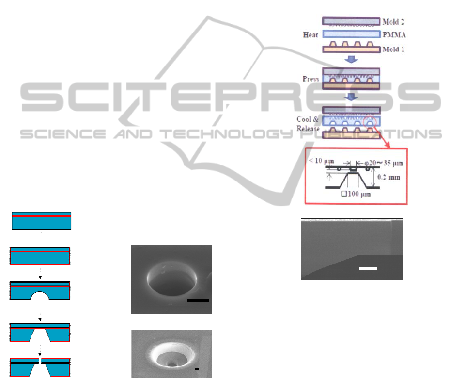
Figure 1: Fabrication process of the Si chip (left) and the
top side (right upper) and back side (right lower) view of
the chip. Scale bar is 0.5 μm.
2.1.2 Plastic (PMMA) Chip
Plastic substrate has several advantages such as
lower cost, easiness in 3D micro structure
formation and in surface chemical
modifications. We have used PMMA for the
substrate material of multi-channel devices.
Fabrication process and the cross sectional view
of the chip are shown in Fig. 2a and b,
respectively. The basic structure of the
substrate was formed by both side hot
embossing, and the micropore was formed by
FIB. The micro fluidic structure was formed on
the upper surface of the substrate, and the
pipette solution well was formed at the lower
side.
a)
b)
Figure 2: Fabrication process of PMMA chip (a) and the
cross sectional view of the thin film region of the pipette
solution well part observed by scanning electron
microscopy (b). Scale bar is 5 μm.
The mold of brass for forming the pipette
solution wells (Mold 1 in Fig.2a), by which thin film
structures with 5~10 μm thickness were formed, was
fabricated by ultra-precision machining equipment
of Dr Omori’s group, RIKEN Japan . Upper mold
of nickel (Mold 2 in Fig.2a) for the micro fluidic
structure formation was fabricated by
electroforming, for which the master mold was
formed by the photolithography using positive resist
on the Si substrate.
Oxidation
Diamond
TMAH
etchin
BIODEVICES 2012 - International Conference on Biomedical Electronics and Devices
144

2.2 Biosensor Chamber and the Stable
Electrode
The 7 x 7 mm
2
(Si) or 11 x 11 mm
2
(PMMA) chip
was sandwiched by PDMS plates, and the sensor
structure was constructed as is shown in Fig. 3. We
fabricated the stabilized AgCl/Ag electrodes, where
the AgCl/Ag wire was inserted into glass tube of 1
mm inner diameter filled with the saturated KCl and
AgCl solution and the top of the glass tube was
sealed by the Vycor glass (Corning). We used these
stabilized electrodes for both upper side (bath
solution , ground) and lower side (pipette solution)
electrodes of the biosensor.
Cell
Figure 3: Schematic structure of the ion channel biosensor.
2.3 Expression of ChR2 and ChRWR
We used in this work channelrhodopsin 2 (ChR2)
and the chimeric channelopsin between chop1 and
chop2, which we call channelrhodopsin/wide
receiver (ChRWR), as light-gated ionchannel
molecules. HEK293 cells, which were a generous
gift from Mr. Minoru Wakamori at Tohoku
University, were cultured at 37℃ and 5% CO
2
in
Dulbecco’s modified Eagle’s medium (Sigma)
supplemented with 10% fetal bovine serum and
transfected with cDNA of channelrhodopsin-Venus
using Effectene transfection reagent (Qiagen, Tokyo,
Japan) according to the manufacturer’s instructions.
After cloning twice with the addition of G418 in a
10 cm dish, single colonies with bright Venus
fluorescence were selected by using a cloning
cylinder IWAKITE-32 (Asahi Glass Co., LTD,
Japan) and cultured in a medium containing G418
until they were confluent in the dish.
2.4 Culture in Biosensor
The surface of the sensor chip was coated with
extracellular matrixes (ECMs), collagen type 4
(BD), which was diluted using 1 mM HCl to 100
μg/ml. 50 μl of the solution was dropped on the
substrate surface, followed by incubation for 2 ~ 4 h
at room temperature. At this stage, the surface
densities of the ECM were about 3 ~ 5 μg/cm
2
. After
removing excess solution, the substrate was rinsed
with sterilized water, dried under a gentle nitrogen
stream, and kept sterile before use. HEK293 cells
were cultured in dishes filled with the medium under
the conventional incubating conditions, i.e., 37°C
and 5% CO
2
. The culture medium was supplemented
with DMEM to which 10% (v/v) FBS, 1% (v/v)
GlutamaxTM (Gibco), and 0.5% (v/v)
penicillin/streptomycin (Gibco) were added. After
cells were detached from the culture dishes, the cell
suspension was seeded at a density of 100 ~ 300
cells/mm
2
on the chip coated with ECM. Channel
current was measured after about 70% confluence
was reached in the biosensor.
2.5 Measurement of Light-gated
Ionchannel Current
The electrical measurement systems were almost the
same as those used in conventional pipette patch-
clamp experiments. The culture medium was
replaced with buffer. We used several of the buffer
solutions reportedly used in experiments on ChR2.
A typical bath solution in the upper chamber
contained (in mM): 140 NaCl, 3 KCl, 10 4-(2-
hydroxyethyl)-1–piperazineethanesulfonic acid
(HEPES), 2.5 CaCl
2
, 1.25 MgCl
2
, and 10 glucose at
pH 7.4 (with HCl). The lower chamber solution
(pipette solution) contained (in mM): 40 CsCl, 80
CsCH
3
SO
4
, 1 MgCl
2
, 10 HEPES, 2.5 MgATP, 0.2
Na
2
EGTA, (pH 7.4). All data were recorded using a
patch-clamp amplifier (Axopatch 200B) at room
temperature. Data were obtained at a 1-kHz cutoff
frequency and an output gain of 1 mV/pA, and they
were analyzed using pClamp 9.2 software. For
whole-cell current recordings, sub-nm conductive
pores through the cell membrane, which electrically
connected the inside of the cell to the lower
chamber, were formed by applying nystatin (Sigma)
solutions to the lower chamber. The nystatin stock
solution was prepared by dissolving nystatin in 1 ml
of methanol and successively adding 45 μl of HCl (1
M) and 45 μl of NaOH (1 M), which was then
diluted with the lower chamber solution to final
concentrations of 100-200 μg/ml before use. The
formation of the whole-cell arrangement was
confirmed by there being a capacitance increase of
about 6 pF in a time interval of 5-10 min after
addition of the nystatin solution to the lower
chamber. The laser beam from the semiconductor
laser with a 473-nm peak wavelength and 3.2-mW
INCUBATION TYPE PLANAR PATCH CLAMP BIOSENSOR - Basic Performances
145
maximum output power (Sumitomo Osaka Cement
Co.,Ltd) was guided by optical fiber and focused
with a micro lens with a 26.5 mm focusing length
under the fluorescence microscope’s objective lens
(OLYMPUS). The diameter of the laser beam at the
focusing point was 30 - 100 μm.
3 RESULTS AND DISCUSSION
3.1 Noise Properties of Incubation
Type Planar Patch Clamp Biosensor
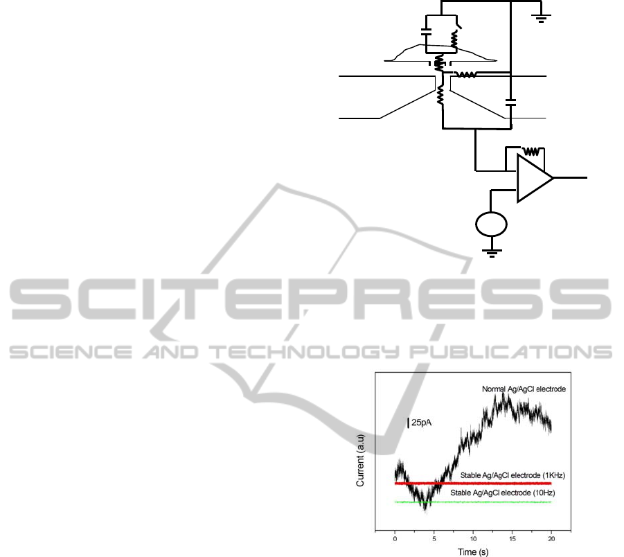
We consider the noise properties using the
equivalent circuit of the planar patch clamp
biosensor shown in Fig.4. The first noise source is
the current noise (I
h
) resulting from the interaction
of the head-stage input voltage noise (e
n
), the input
capacitance (C
t
) and the frequency bandwidth of the
circuit (B), described by eq. (1) (Mayer, 2003).
In
the following, all current noises are given by root-
mean-square (rms) values.
I
h
2
= (4/3)e
n
2
π
2
C
t
2
B
3
(1)
C
t
= C
m
+C
s
(2)
We used a value of e
n
= 2.3 x 10
-9
V Hz
-0.5
reported for the cooled type capacitor feedback
patch clamp amplifier (Axopatch 200B). C
t
is the
total input capacitance given by eq. (2), C
m
is the
membrane capacitance and Cs is the capacitance of
the substrate. The thermal voltage noises (Johnson
voltage noise) due to the access resistance R
a
and
seal resistance R
j
cause the current noise, I
Ra
and I
Rj
,
respectively as shown in eq. (3) (Mayer, 2003). The
resistances of the ion channels, R
m
and R
p
are usually
sufficiently larger than R
a
and R
j
, thus the
contribution to the thermal noise can be ignored. In
the incubation type planar patch clamp, contribution
of the seal resistance to the thermal noise often can’t
be ignored.
I
R
2
= 4kTB/R R = R
a
or R
j
(3)
where, k is the Boltzmann constant (k = 1.38 x 10
-23
J K
-1
), T is the absolute temperature.
In the case of the low seal resistance region, 1/f
noise called excess noise, which possibly is
generated by the current flowing at the narrow micro
pore region, becomes important. The spectral
density of the excess noise current, S
ex
2
, is given by
S
ex
2
= KI
2
/fR
a
2
(4)
Cm
Rm
R j
Ra
Rp
Vm
Cs
Sw
Figure 4: Equivalent circuit of the planar patch clamp
biosensor. C
m
: cell membrane capacitance, Sw:
ionchannel, R
m
, R
p
: resistance of corresponding ion
channel, R
j
: seal resistance, R
a
: access resistance, C
s
:
capacitance of the substrate, V
m
: applied membrane
voltage.
Figure 5: Observed current noise in the biosensor system
shown in Fig. 3 using PMMA substrate, for normal and
stabilized AgCl/Ag electrodes.
Where K is a constant and I is total current which is
approximately given by V
m
/(R
j
+ R
a
). The total rms
value of the current noise (I
t
) can be calculated
using eq. (5).
I
t
= ( I
h
2
+ I
Ra
2
+ I
Rm
2
+ I
ex
2
)
1/2
(5)
Other than these intrinsic noise, fluctuation of
the offset voltage (
Δ
V
m
) of the electrode, which
often becomes larger than 1 mV, causes the
significant fluctuation of the base line. So it is often
important to use the stablized electrode in the
incubation type planar patch clamp as shown in Fig.
5. Here we calculate the noise current for the typical
cases, C
t
= 20 pF, B = 10
3
Hz, R
a
= 2 MΩ and R
j
=
BIODEVICES 2012 - International Conference on Biomedical Electronics and Devices
146
10 MΩ, I
h
= 0.005 pA, I
Ra
= 2.8 pA, and I
Rj
= 1.2 pA
are obtained. So, if I
ex
2
is ignored, the total rms
value of the current noise is evaluated to be I
t
= 3.1
pA. This value is slightly smaller than the observed
value ~ 7 pA (1kHz) shown in Fig. 5. The
difference, ~ 4 pA, may be due to the excess noise,
since 1/f noise is dominant in the present seal
resistance region (data are not shown).
From these analysis, it is concluded that the
measurement of the whole cell mode which usually
gives the current level of several tens pA or larger
can be easily attained by using the stable electrode.
It is, however, necessary to increase the seal
resistance by about one order of magnitude (~100
MΩ) to realize the single channel recordings in our
system.
3.2 Light-gated Ion Channel Method in
the Incubation Type Planar Patch
Clamp Biosensor
The recently developed light-gated ion channel
method has brought a significant progress into the
neural network analysis field due to its temporal and
spatial high resolutions. Since the in vitro neural
network analysis and its application to the high
throughput screening is an important application of
the incubation type planar patch clamp method, here
we investigate the basic property of the light-gated
ion channel on the incubation type planar patch
clamp biosensor.
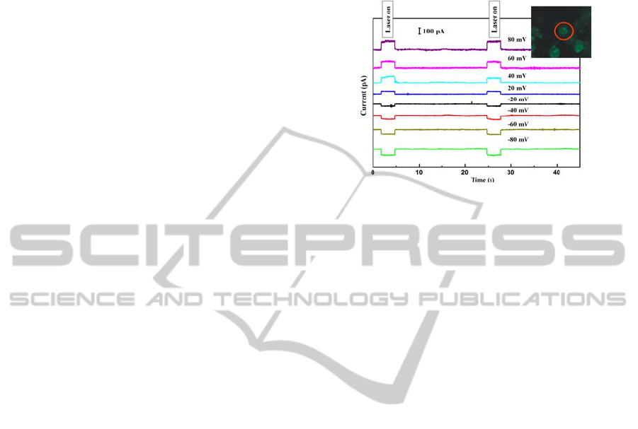
ChRWR-expressing HEK293 cells were seeded
on the chip of the incubation type planar patch
clamp biosensor. After the cells became almost
completely confluent, we observed the
characteristics of the laser stimulated channel
currents as shown in Fig. 6. The observed channel
current pulse signals were similar in shape and
signal to noise ratio to those observed in the pipette
patch clamp method, although the seal resistance
was much smaller than a giga-ohm. These data
suggest that light-gated method is useful not only in
the neural network analysis but also useful in the
performance test of the biosensor due to its
simplicity in handling.
3.3 Biosensor Operation using
TRPV1-expressing HEK293 Cells
The unique points of ion channel biosensor is highly
selective direct responses to various kind of ligand
molecules and also sensitive responses to physical
stimuli. Ion channels are also important drug targets
and the biosensor is a potentially unique device for
high throughput drug screening. It also finds its
application in the detection of biological warfare
agents (Bayley, 2001).
Figure 6: Observed ion channel current under voltage
clamp of 473-nm laser irradiation with ChRWR-
expressing HEK293. Ion channel current wave forms
depend on the applied membrane potentials.
TRPV1 receptor, a nonspecific cation channel
with preference for Ca
2+
, is mainly expressed in
sensory nerves from peripheral terminal to central
endings, which can be activated by vanilloids such
as capsaicin. Capsaicin is the pungent ingredient of
hot pepper, which elicits a sensation of burning pain
by selectively activating sensory neurons to transfer
the noxious stimuli to the central nervous system
(Caterina, 1997).
We have constructed ionchannel biosensor using
TRPV1-expressing HEK293 cells (gift from Prof.
Tominaga at National Institute for Physiological
Sciences) and applied to the capsaicin detection.
The surface of the SOI sensor chip were coated
with collagen type 4. After the cell covered on the
pore and spread, the resistance R
j
of the cleft
between the cell membrane and substrate surface
was measured (10.2 MΩ), then the perforated
whole-cell configuration was formed by the
application of nystatin to the pipette solution side.
Then, the whole-cell current of TRPV1-expressing
HEK 293 cell activated by capsaicin application was
recorded as shown in Fig. 7.
The concentration of capsaicin was 3.3 μM. The
desensitization was observed in the second injection
of capsaicin (Caterina, 1997). The noise level of our
experimental station was 7 pA using 1 kHz low pass
filter (Fig. 5). The magnitude of the single channel
current of TRPV1 is observed by pipette patch
clamp method to be about 4pA at the membrane
voltage +60 mV (Caterina, 1997). So we think that
single channel recording maybe realized even in our
incubation type planar patch clamp system by
several times increase of the seal resistance.
INCUBATION TYPE PLANAR PATCH CLAMP BIOSENSOR - Basic Performances
147

CAP
Figure 7: Whole cell channel current record of TRPVI
expressed on HEK293 cell by capsaicin stimulations
measured by ion channel biosensor based on the
incubation type planar patch clamp method.
4 CONCLUSIONS
Ion channel biosensor based on the incubation type
planar patch clamp method was developed and the
basic properties were investigated. Due to the
existence of ECM protein at the cleft between the
cell membrane and the substrate surface near the
miropore, it is not easy to realize the high seal
resistance (giga-ohm seal). In the present case using
collagen 4 as ECM, the seal resistance was usually
about 10 MΩ, and the noise level was 7 pA with the
1 kHz low pass filter. The main noise sources were
excess current noise and the thermal noise generated
at micro pore resistance (R
a
) and the seal resistance
(R
j
). All these noises can be reduced by increasing
the seal resistance. Operation of the light-gated ion
channel, ChRWR, was investigated by the
incubation type planar patch clamp method using
laser (λ = 473 nm) stimulations. The channel
current profile and its membrane potential
dependence well agreed to the reported data
measured by pipette patch clamp method. So we
think that light-gated method is also useful in the
neural network function analysis and high
throughput screening application based on the
incubation type planar patch clamp method, and also
useful in the simple performance check of these
devices. The biosensor operation was examined
using TRPV1-expressing HEK293 cells. Quite high
sensitivity was confirmed. But for the single channel
recording, more than several times improvement of
the seal resistance is required.
ACKNOWLEDGEMENTS
We appreciate Dr. Hitoshi OHMORI and Mr.
Yosuke HACHISU at RIKEN for their support in
making brass mold by ultra-precision machining
equipment.
REFERENCES
Bayley, H., Cremer, P.S., 2001. Nature 413, 226.
Caterina, M. J., Schumacher, M. A., Tominaga, M.,
Rosen, T. A., Levine, J. D., Julius, D., 1997. Nature
389, 816.
Erickson, J., Tooker, A., Tai, Y. C., Pine, J., 2008.,
Journal of Neuroscience Methods 175, 1.
Fertig, N., Blick, R. H., Behrends, J. C., 2002. Biophys. J.
82,3056.
Li, X. H., Klemic, K. G., Reed, M. A., Fred, J., Sigworth,
F. J. 2006. Nano Letters 6 , 815.
Matthews, B., Jack, W., 2006. J. Microelectromech. 15
214.
Mayer, M., Kriebel, J. K., Tosteson, M. T., Whitesides, G.
M., 2003. Biophysical J. 85, 2684.
Pantoja, R., Nagarah, J. M., Starace, D. M., Melosh, N. A.
Blunck, R., Bezanilla, F., Heath, J. R., 2004. Biosens.
Bioelectron. 20, 509.
Petreanu, L., Huber, D., Sobczyk, A., Svoboda, K., 2007,
Nature Neurosci. 10, 663.
Reska, A., Gasteier, P., Schulte, P., Moeller, M.,
Offenhäusser, A., Groll, J., 2008. Advanced Materials
20,2751.
Sett, A, Burkhardt, C., Weber, U., Stiphout, P.V., Knott,
T. 2003. Receptors and Channels 9, 59.
Sordel, T., Garnier-Raveaud, S., Sauter, F., Pudda, C., F.
Marcel, F., Waard, M. D., Arnoult, C., Vivaudou, M.,
Chatelain, F., Picollet-D’hahan, N., 2006. J.
Biotechnol. 125, 142.
Tao, H. W., Zhang, L. I., Bi, G., Poo, M., 2000. J.
Neurosci. 20, 3233.
Taylor, A. M., Dieterich, D. C., Ito, H. T., Kim, S. A.,
Schuman, E. M. 2010. Neuron 66, 57.
BIODEVICES 2012 - International Conference on Biomedical Electronics and Devices
148
