
CARDIAC PATHOLOGIES DETECTION OVER FPGA USING
ELECTROCARDIOGRAM
Ariadna Vázquez-Sedano, Santiago T. Pérez-Suárez, Carlos M. Travieso-González
and Jesús B. Alonso-Hernández
Signal and Communication Departament, Institute for Technological Development and Innovation in Communications
University of Las Palmas de Gran Canaria, Campus of Tafira, 35017, Las Palmas de Gran Canaria, Spain
Keywords: Electrocardiogram, Discrete wavelet transform, Artificial neural network, Field programmable gate array,
Xilinx, System generator, Simulink.
Abstract: In this work is presented an implementation of an automatic detection system for the heart diseases over a
field programmable gate array (FPGA). The system is able to process, analyse and classify the cardiac
pathologies in real time from electrocardiogram (ECG). These algorithms principally are based on Digital
Wavelet Transform (DWT) techniques, and Principal Component Analysis (PCA). Finally, cardiac pulse
detection and classification algorithms have been implemented in an Artificial Neural Network (ANN).
Furthermore, the subjectivity problem in the heart disease diagnosis is solved, and the task of heart
specialist is facilitated.
1 INTRODUCTION
Some developments of Bioengineering are focused
on the implementation biomedical and electrical
equipment to measure physiological variables of the
heart, due to cardiovascular diseases (CVDs) are the
main cause of death worldwide (WHO, 2011). For
this reason, it work wants to contribute to advances
in diagnosis of CVDs. Technology offers the
possibility of designing an appropriate tool to
facilitate the work of the specialist doctor. The
electrocardiogram (ECG) is an efficient tool for
detection, and prevention from heart diseases,
therefore the premature diagnostics of the heart
malfunctions is crucial.
Several international projects, about ambulatory
monitoring systems or detectors of heart diseases,
are only focusing on the shape of the QRS complex,
that is to say, on QRS temporal information. For
example, works which are based on abnormal ECG
activity due to RR interval, QRS width or ST shape
(Lee et al., 2007). Also, another research only
detects the level change of ST shape. The classifier
of ST shape type uses a polynomial approximation
to distinguish an ischemic ST from a non-ischemic
one (Gu-Young and Kee-Ho, 2007).
In this study has been proposed to discriminate
eight heartbeats (MIT-BIH DB, 2011). In the context
of classification, Artificial Neural Network (ANN)
has been proposed (Chen et al., 2008). The main aim
of this work has been to implement this automatic
detector of heart diseases over Field Programmable
Gate Array (FGA). This type of logical
programmable devices are quite suitable to
implement ANN systems (Pérez et al., 2011), and
wavelet digital filters (Ballesteros, 2004).
2 SYSTEM DESIGN INTO FIXED
POINT
In this section has been performed the completely
detector design into functional blocks (with
Simulink and tools of System Generator of Xilinx),
for this reason, it has been necessary to convert
floating point signals (obtained by Matlab), into
fixed point signals in order to be implemented over
FPGA
2.1 Programmable Logical Device,
FPGA
Field Programmable Gate Array (FPGA) is a digital
integrated circuit that is configured by the designer
from a personal computer, without sending it to the
360
Vázquez-Sedano A., T. Pérez-Suárez S., M. Travieso-González C. and B. Alonso-Hernández J..
CARDIAC PATHOLOGIES DETECTION OVER FPGA USING ELECTROCARDIOGRAM.
DOI: 10.5220/0003766403600364
In Proceedings of the International Conference on Bio-inspired Systems and Signal Processing (BIOSIGNALS-2012), pages 360-364
ISBN: 978-989-8425-89-8
Copyright
c
2012 SCITEPRESS (Science and Technology Publications, Lda.)
manufacturer; it can be reprogrammed even if it has
been placed in the printing circuit board.
The FPGA is programmed by downloading a file
called bitstream to a memory in the system. A FPGA
consists in digital configurable resources which can
perform arithmetic and logic functions.
Xilinx Company is one of the most extended
manufacturers of FPGA. Xilinx offers System
Generator (Xilinx, 2011) that is one design tool in
Simulink of Matlab (MathWorks, 2011). System
Generator allows the fast design of systems using
block diagrams, and its simulation even before the
compilation. The compilation generates the files
necessary for the Integrated System Environment
(ISE) of Xilinx for FPGA, where the description of
the circuit is obtained in a standard hardware
description language, like: Very High Speed
Integrated Circuit Hardware Description Language
(VHDL) (Pardo and Boluda, 2004). In ISE it is
possible to compile the hardware description
language files, and simulate the system behavioral or
timing analysis. Afterwards the program file can be
generated for the chosen device. Finally this file can
be downloaded from the computer to the board
where the FPGA is included.
2.2 Design Methodology
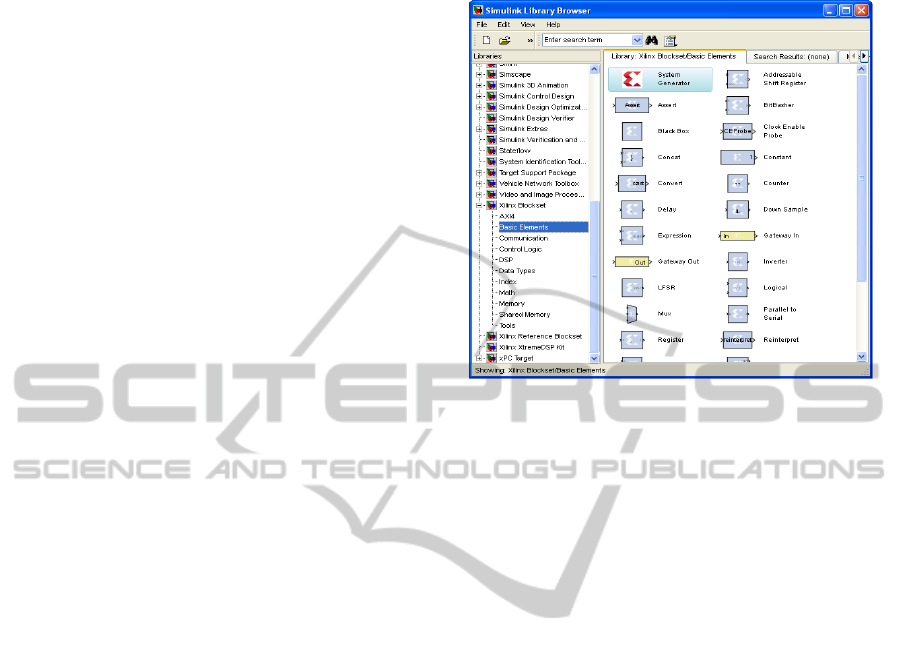
System Generator version 13.1 has been used in this
design. When System Generator is installed some
Blocksets (see Figure 1) are included in Simulink of
Matlab (version R2008b). Each block is configured
opening its dialog window; this permits fast and
flexible designs.
The FPGA boundary from the Simulink
simulation model is defined by Gateway In and
Gateway Out blocks. The Gateway In block converts
the floating point input into fixed point format,
saturation and rounding modes can be defined by the
designer. The Gateway Out block converts the
FPGA fixed point format to Simulink double
numerical precision.
In System Generator the designer does not
perceive the signals like bits; instead the bits are
grouped in signed or unsigned fixed point format.
The operators force signals to change automatically
to the appropriate format in the outputs. A block is
not a hardware circuit necessarily, it relates with
others blocks to generate the appropriate hardware.
The designer can include blocks described in a
hardware description language, finite state machine
flow diagram, Matlab files, etc. The System
Generator simulations are bits and cycle accurate;
this means results seen in simulation exactly match
the results seen in hardware.
Figure 1: Simulink xilinx DSP blockset libraries.
The Simulink signals are shown as floating point
values, which makes easier to interpret them. The
System Generator simulations are faster than
simulators, and the results are easier to analyze.
Otherwise the VHDL is not portable to others FPGA
manufacturers, the reason of this is that System
Generator uses Xilinx primitives which take
advantages of the device characteristics.
System Generator can implement a complete
design in a hardware description language hardware
description language (VHDL). Designs in System
Generator are discrete time systems, the signals and
blocks generate automatically the sample rate,
however a few blocks set the sample rate implicitly
or explicitly. System Generator supports multirates
circuits and some blocks can be used for changing
the sample rate.
Often an executable specification file is created
using the standard Simulink Blocksets. The
specification file can be designed using floating
point numerical precision and not hardware detail.
Once the functionality and basic dataflow have
been defined, System Generator can be used to
specify the hardware implementation details for the
Xilinx devices. System Generator uses the Xilinx
DSP Blockset from Simulink and will automatically
invoke Xilinx Core Generator to generate highly
optimized netlists for the building blocks. System
Generator can execute all the downstream
implementation tools to get a bitstream file for
programming the FPGA device. An optional
testbench can be created using test vectors extracted
from the Simulink environment for using with ISE
simulators.
CARDIAC PATHOLOGIES DETECTION OVER FPGA USING ELECTROCARDIOGRAM
361
Every system designed with System Generator
must contain a System Generator and it specifies
how simulation and code generator can be used.
Firstly, in System Generator block the type of
compilation can be specified to obtain: HDL netlist
and Bitstream. Secondly, the FPGA type can be
chosen. The Target directory defines where the
compilation writes the files of ISE project. The
Synthesis tool specifies which tool is chosen for
synthesizing the circuit: Xilinx Synthesis Tool
(XST). In Hardware description language the
designer can choose between VHDL, Clock Options
defines the period of the clock and the Simulink
system period. When the designer clicks on
Generate in dialog window System Generator Block
the structural description files in a hardware
description language are obtained, and a project is
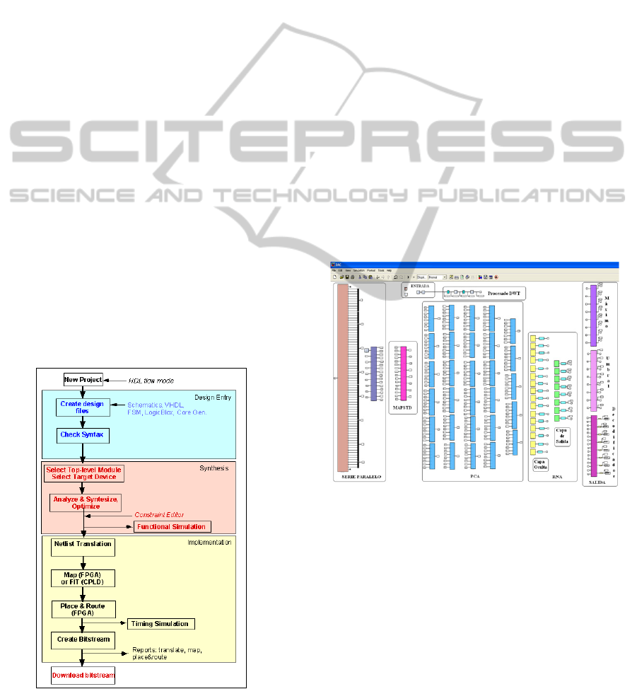
created for ISE version 13.1. The first step in the
compilation process is synthesizing the system
(Figure 2). The synthesis tool used is Xilinx
Synthesis Tool (XST). It is an application which
creates Xilinx specific netlist files called NGC files.
This file is a netlist that contains both logical design
data and constraints. The NGC file takes the place of
both Electronic Data Interchange Format (EDIF) and
Netlist Constraints File (NCF) files. After Synthesis
is obtained a report and it can be analyzed by the
designer; moreover, the designer can view Register
Transfer Level (RTL) schematic or technology
schematic. After synthesizing the system the design
is implemented in three stages: translate, map and
place and route.
Figure 2: Design flow process into system generator and
ISE.
The translation process merges all the input
netlists and design constraint information and
outputs a Xilinx Native Generic Database (NGD)
file. Then the output NGD file can be mapped to the
targeted FPGA device family. The map process
takes the NGD file, runs a design rule checker and
maps the logic design to a Xilinx FPGA device. The
results appear in a Native Circuit Design (NCD) file,
which is used for placing and routing. The place and
route process takes a NCD file and produces a new
NCD file to be used by the programming file
generator. The generated programming file process
runs the Xilinx bitstream generation program BitGen
to produce a bit file for Xilinx device configuration.
Finally, the target device uses the bit file to
configure the FPGA target device.
3 DETECTOR DESIGN
In this section is showed the developed detector into
System Generator of Xilinx. It has been designed
with several blocks of Xilinx and other blocks which
have been made of own implementation (see Figure
3).
Figure 3: Heart diseases detector.
3.1 Processing Block
The main function of process is the characterization
of 8 beat types of ECG signals. The parameterization
is based on DWT as it has been previously explained
(see Figure 4). It is composed by: ROM block where
the input signal, which has been extracted from
preprocessing step, is stored.
This signal has 300 samples. The other blocks to
implement DWT are: two transpose form II filters,
which are the DWT filters and two decimator blocks
(“Down Sample Block”) (see Figure 4). After that,
BIOSIGNALS 2012 - International Conference on Bio-inspired Systems and Signal Processing
362
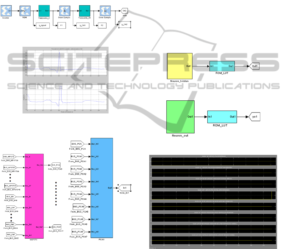
the DWT coefficients are obtained. This new signal
has only 75 samples. The number of samples has
been decreased due to the decimators (Figure 5).
Before applying the PCA, it is important to
normalize the input signal samples with “MAPSTD
Block” (see Figure 6.a). In order to reduce the
number of samples from input signal, it has been
implemented the following 29 PCA blocks. One
block for each sample of transformation matrix,
which is used in PCA technique (Figure 6.b).
Figure 4: Designed processing block.
Figure 5: ECG beat signal before and after being
processed with DWT.
a) b)
Figure 6: a) Normalization block; b) One of the PCA
blocks.
3.2 Neural Network: Classifier Block
The ANN has been designed so that the classifier
recognizes 8 different classes. Its architecture
consisted on (see Figures 7 and 8):
Input Neurons: the 29 output from each PCA
block are introduced into the classifier like input
single signal.
Hidden Neurons: with 16 neurons.
Output Neurons: the 8 neurons one for each beat
type that are classified.
The “ROM_LUT Blocks” implement the
logarithmic sigmoid function.
The last three blocks are: “MAX Block”,
“UMBRAL Block” and “DECODIFICADOR
Block”. They are implemented to indicate the
detected beat type at the exit from the classifier.
When the beat type has been classified this output is
put to “1” and the rest of the outputs to “0” (see
Figure 9). For example if is introduced at the
detector entrance a P beat it is obtained “1” at that
exit.
Figure 7: Hidden Neuron from Hidden Layer.
Figure 8: Output neuron from output layer.
Figure 9: P beat type detected (set up “1”).
4 RESULTS
In this study, the Massachusetts Institute of
Technology-Beth Israel Hospital (MIT-BIH)
database has been chosen (MIT-BIH Arrhythmias
DB, 2011). This DB contains a large number of
CARDIAC PATHOLOGIES DETECTION OVER FPGA USING ELECTROCARDIOGRAM
363

records from ECG. It is composed of 48 ECG
recording from modified limb lead II (MLII) leads
which are thirty minutes each, and it has over 20
different types of ECG pulses. It has been
constructed a reduced database with 22 records from
these 48 registers. Every beat type is composed by
750 beats. Half of these 750 beats will be used for
training phase and another half for the verification
phase. The detector only detects 8 types of pulse,
which appear with more frequency in this database.
For our experiments, each ANN parameter has
been analyzed to determine if the sign bit is needed,
the minimum number of bits of the integer part for
covering the range and the minimum number of bits
of the decimal. After that the ANN architecture has
been defined and initialized System Generator
simulations can be performed. In these simulations
(fixed point input values) the 98.25% accuracy is
reached with only 1.75% of error (see Table 1).
Table 1: Results of Complete Designed System on Fixed
Point Results.
The chosen FPGA device has been Virtex 7 of
Xilinx and it has been implemented in VHDL. This
implementation in Xilinx allows timming simulation
and its delay is 158.23 ns (much lower than Matlab
delay, about 6.56 ms). The ISE software provides a
power estimator that indicates an estimated power
consumption of 9.3 watts and an estimated
temperature of 42 centigrade degrees in the FPGA.
The occupation in the FPGA is about 45.2% for
logical resources and 39.5% for input-output pins.
5 CONCLUSIONS
In this work, a prototype has been developed on
FPGA, after to observe the conditions of data
dimensions for this device are flexible and highly
parallel architectures, and therefore, it can be built.
These are the reasons that FPGA is suitable for
Digital Signal Processing (DSP). As well as, optimal
results have been reached, the automatic cardiac
pathology detector has a 98.63% of success and the
behaviour simulation of FPGA has been tested in
System Generator with excellent results.
For a close future, this design maybe can be
included in a prototype detector for heart disease
that has elements of communication via infrared,
bluetooth or wi-fi. These radiofrequency signals can
be sent with result from the detection of ECG beat,
so the doctor can have an objective diagnosis in real
time and accurate results on his PDA or personal
computer.
ACKNOWLEDGEMENTS
This work has supported by Cátedra Telefónica –
ULPGC 2010, under the reference, ARUCAS_2010.
REFERENCES
WHO, 2011.World Health Organization. Cardiovascular
Diseases (CVDs). Last view: 07/17/2011.
http://www.who.int/mediacentre/factsheets/fs317.
Lee, D., Bhardwaj, S., Alasaarela, E., Wan Young, Ch.,
2007. An ECG Analysis on Sensor Node for Reducing
Traffic Overload in u-Healthcare with Wireless Sensor
Network.In IEEE SENSOR 2007 Conference.IEEE.
Gu-Young, J., Kee-Ho, Y., 2007.Development of
Ambulatory ECG Monitoring Device with ST Shape
Classification. In ICCAS’07, International Conference
on Control, Automatic and Systems.IEEE.
MIT-BIH DB, 2011. Massachusetts Institute of
Technology –Beth Israel Hospital Database.
Last View: 07/16/2011. http://physionet.org/physiobank/
database/mitdb/
Chen, T., Zheng, Y., Han, L., Guao, P., He, X., 2008. The
Sorting Method of ECG Signlas Based on Neural
Network. In ICBBE 2008, 2
nd
International
Conference on Bioinformatics and Biomedical
Engineering.IEEE.
Pérez, S., Vásquez, J., Ticay, J., Alonso, J., Travieso, C.,
2011. Artificial Neural Network in FPGA for Pejibaye
Palm Classification using Molecular Markers. In
EUROCAST 2011, 13
th
International Conference on
Computer Aided System Theory.IUCTC.
Xilinx, 2011. http://www.xilinx.com/tools/sysgen.htm.
MathWorks, 2011. Last view: 09/01/2011.
http://www.mathworks.es/index.html
Pardo, F., Boluda, J., 2004. VHDL.Language for synthesis
and model circuits. Ra-Ma Editorial, 2
nd
edition.
Ballesteros, D., 2004. FIR Filter Design on FPGA for
Wavelet Background Noise Removal in Bioelectric
Signals. Last view: 08/03/2011. http://redalyc.
uaemex.mx.
BIOSIGNALS 2012 - International Conference on Bio-inspired Systems and Signal Processing
364
