
COMBINED STIMULATION AND MEASUREMENT SYSTEM
FOR ARRAY ELECTRODES
Markus Valtin
1,2
, Thomas Schauer
1
, Carsten Behling
2
, Michael Daniel
2
and Matthias Weber
2
1
Control Systems Group, Technische Universit¨at Berlin, Straße des 17. Juni 135, Berlin, Germany
2
HASOMED GmbH, Paul-Ecke-Straße 1, Magdeburg, Germany
Keywords:
Multi-channel transcutaneous electrical stimulation, Array electrode, Electromyography.
Abstract:
Array electrodes have the potential to significantly advance Functional Electrical Stimulation (FES) perfor-
mance and patient compliance by optimizing the electrode position. To evaluate the potentials and for research
purposes, an universal stimulation system for array electrodes has been developed. The system additionally
features volitional EMG recording from the array electrodes during active stimulation. Multiple devices, one
stimulator and at least one demultiplexer, are synchronized to deliver up to 10 stimulation pulses per stimula-
tion cycle at a frequency of ≈ 420Hz. A typical stimulation cycle period is 50 ms. The real-time controllable
array electrode can include up to 60 elements for the active electrode and up to 4 elements for the indifferent
electrode. A small switch module permits placement near the array electrode, eliminating extensive wiring.
The stimulation system is fully controllable from a PC via USB interfaces.
1 INTRODUCTION
For selective transcutaneous Functional Electrical
Stimulation (FES) it is important to place one smaller
active electrode over the motor point of the target
muscle to achieve optimal results. Motor points
are areas where muscles are most likely to be acti-
vated. Finding these motor points requires some ex-
pertise and often another placement point achieves
better results because of patient specific character-
istics (O’Dwyer et al., 2006) (Popovi-Bijeli et al.,
2005). In FES, usually biphasic, charge balanced,
stimulation pulses are applied. The larger indiffer-
ent electrode is placed away from any motor point to
avoid that the compensating pulse generates an action
potential.
Array electrodes have the potential to simplify the
electrode placement because any number of array el-
ements can form a “virtual electrode”, which can dy-
namically change position and size. This, together
with intelligent control software, allows automatic
optimization towards the distinctive, real motor point
of the target muscle, even for imprecise placement of
the array electrode (Keller et al., 2006). Array elec-
trodes also allow a much more precise muscle activa-
tion in areas like the forearm, where a lot of different
muscles are close together.
A number of research projects used array elec-
trodes because of the above mentioned advantages.
The presented studies demonstrated that a selective
stimulation of the forearm muscles by array elec-
trodes can be realized to induce precise finger and
wrist-joint movements (Popovi-Bijeli et al., 2005)
(O’Dwyer et al., 2006). A selective correction
of a drop-foot in hemiplegics was investigated in
(Azevedo-Coste et al., 2007). The largest applied
electrode array comprised 60 elements (Keller et al.,
2006). Most stimulation systems presented in litera-
ture serve only one array electrode and do not provide
an open and flexible PC interface for real-time control
of the switch configurations.
2 CONCEPT
The developed system utilizes an already existing 8
channel stimulation device and extend it for use of
array electrodes. This requires the development of a
demultiplexer and the ability to synchronize the dif-
ferent devices.
The stimulation is controlled by a 20Hz top level
control loop, implemented on a designated com-
puter in Scilab/Scicos (http://www.scilab.org) or Mat-
lab/Simulink (http://www.mathworks.com). Every
50ms, the stimulator will generate a sequence of up
345
Valtin M., Schauer T., Behling C., Daniel M. and Weber M..
COMBINED STIMULATION AND MEASUREMENT SYSTEM FOR ARRAY ELECTRODES.
DOI: 10.5220/0003786303450349
In Proceedings of the International Conference on Biomedical Electronics and Devices (BIODEVICES-2012), pages 345-349
ISBN: 978-989-8425-91-1
Copyright
c
2012 SCITEPRESS (Science and Technology Publications, Lda.)
to 10 stimulation pulses that are distributed to normal
stimulation channels or channels with a demultiplexer
(arrays). Therefore, the top level control loop trans-
mits a sequence configuration to the stimulator and to
the demultiplexer(s) every 50 ms.
The sequence configuration consist of up to 10 in-
dividual configurations for the stimulation pulses and
switch settings. This way the stimulator receives up to
10 pulse configurations which define the pulse width
and stimulation current of each biphasic stimulation
pulse as well as the information to which channel the
pulse has to be delivered. Each demultiplexerreceives
a corresponding number of switch configurations for
the stimulation pulses as well as one optional EMG
switch configuration, if an electromyography (EMG)
signal shall be recorded from the array electrode. A
switch configuration defines which of the available 64
switches are active.
As soon as stimulator and demultiplexer(s) have
received there configurations they synchronize them-
selves as explained in section 5. The computer on
which the top level control loop runs is not involved
in the synchronization. If applicable the EMG switch
configuration is set after all stimulation pulses of that
stimulation cycle have been sent.
Figure 1 shows an example with a stimulation se-
quence for only one demultiplexer (array) where 4
distinctive muscles are activated.
1 2
3
4
5 6 7 8 9 10
comm. (seq. configuration)
one pulse
sequence lenght
500
t [ms]
1 2
3
4
5 6 7 8
9
10
one switch setting
500
t [ms]
5 EMG 11 EMG
Demultiplexer
Stimulator
1 2
1 2
Figure 1: Example for a sequence of 4 pulses for the stim-
ulator device and one demultiplexer. The largest possible
sequence is indicated in gray.
3 SYSTEM OVERVIEW
The core system consists of a RehaStim
TM
stimula-
tor and at least one demultiplexer. A demultiplexer
distributes one stimulation channel over an array of
small, especially designed electrodes. Up to 8 demul-
tiplexer can be connected to one stimulator but stim-
ulator channels can also be used without the demulti-
plexer.
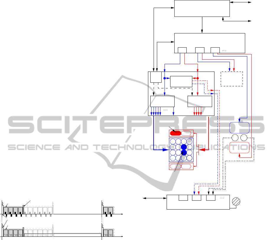
Figure 2 depicts the entire system with all possi-
ble components. For the sake of simplicity, we as-
sume in the following, that only one demultiplexer is
connected to the stimulator.
multi−channel EMG amplifier
USB
to Demux 2
real time controller
(PC with Linux/RTAI)
Ch1 Ch2 Ch3
to EMG
USB
USB
USB
(de−multiplexed current source)
multi−channel stimulator
synchro−
nisation
amplifier
MC
discharging
EMG
plexer 2
covers
of small
muscles
an area
virtual active electrode
virtual indifferent electrode
switches A
protection &
line B1
Array Electrode
A3
covers one muscle
Standard
Pair of
Electrodes
B3
Ch1 Ch2 Ch3
USB to PC
reference
electrode
demulti−
demultiplexer 1
switches B
line A1
Figure 2: System overview.
A standard PC or laptop controls the entire system
by implementing a top level control loop. A real-time
operating system like RTAI (https://www.rtai.org) is
advised but not crucial since the top level control loop
only runs with about 20Hz, providing the next se-
quence configuration for the stimulator and all con-
nected demultiplexer(s). The configuration data is
sent via an USB link to the respective device. No spe-
cial safety precaution is needed since all devices have
galvanic isolated USB ports.
The system uses the certified, current-controlled
8 channel stimulator RehaStim
TM
available from the
company HASOMED GmbH. The stimulator outputs
a biphasic stimulation pulse with a stimulation cur-
rent from 2mA to 130mA and a pulse width from
10µs to 500µs. The RehaStim
TM
device can be di-
rectly controlled by an external device, preferable a
personal computer. The RehaStim
TM
implements a
special operation mode which accounts for the need
of synchronization and pulse sequences.
BIODEVICES 2012 - International Conference on Biomedical Electronics and Devices
346
The hardware design of the demultiplexer, the syn-
chronization process and the EMG measurement in-
cluding EMG amplifier protection are described in
more detail later on.
The demultiplexer can support a width range of
array electrodes with two exclusive sets of array el-
ements. The first set is used to build the virtual ac-
tive electrode and may consist of up to 60 elements.
The second set with maximal 4 elements is used to
build the virtual indifferent electrode. To minimize
losses and to prevent a short circuit due to miscon-
figuration the array elements related to the virtual in-
different electrode must be placed on a different gel
layer than the array elements belonging to the virtual
active electrode.
4 DEMULTIPLEXER DESIGN
The demultiplexer is divided into two parts, a power
module and a switch module. This segmentation al-
lows the switch module to be placed very close to the
array electrode, with a minimum of necessary cables.
Power Module. The demultiplexer is powered from
an external 12V power supply or battery. The power
module hosts the galvanic isolated USB port and the
galvanic isolated SYNC port.
The SYNC port safely connects the demultiplexer
to the RehaStim
TM
stimulator. The signals “Demulti-
plexer Ready” (DMR) and “Stimulation in Progress”
(STIM), which are essential for synchronization, are
routed through the SYNC port. The synchronization
process is further explained in Section 5.
All demultiplexer functions, including communi-
cation, synchronizationand switch operation, are con-
trolled by a Cypress programmable system-on-chip
(PSoC). The 8-bit MCU core uses a 24MHz system
clock, providing sufficient execution speed to ensure
peak performance and minimized stimulation delays.
The power module communicates with the switch
module over a 24MHz differential data link. This
high speed forward channel includes a CRC check to
ensure data integrity. Any error on the switch module
is reported back over a low speed backward channel
and is processed by the PSoC MCU.
Switch Module. The switch module includes the re-
ceiver for the 24MHz differential data link, the ac-
tual switch matrix and the EMG protection circuit.
The switch matrix consists of 64 high voltage CMOS
analog switches and makes a compact design of the
switch module possible.
One of the eight stimulator channels is connected to
the switch module. The stimulation channel’s active
electrode line is connected to 60 switches, allowing
up to 60 array elements to form the virtual active elec-
trode. The stimulation channel’s indifferent electrode
line is connected to 4 additional switches. A short
circuit due to misconfiguration is therefore impossi-
ble. The stimulation voltages can rise up to ±150V.
Therefore two 300V rated 34 pin IDC connectors are
used to connect the demultiplexer with the array elec-
trode.
5 SYNCHRONIZATION
Since the system uses independent devices for gen-
erating the stimulation pulses and controlling the
switches, these devices need to be synchronized. The
demultiplexer must set the switches before any stim-
ulation pulse is generated and move on to the next
configuration as soon as the stimulation pulse is com-
pleted. Therefore the demultiplexer needs to know
when a stimulation pulse is generated and the stimu-
lator needs to know when the switch configuration for
the next stimulation pulse is established. This infor-
mation is encoded into the two synchronization sig-
nals STIM (Stimulation in Progress) and DMR (De-
multiplexer Ready).
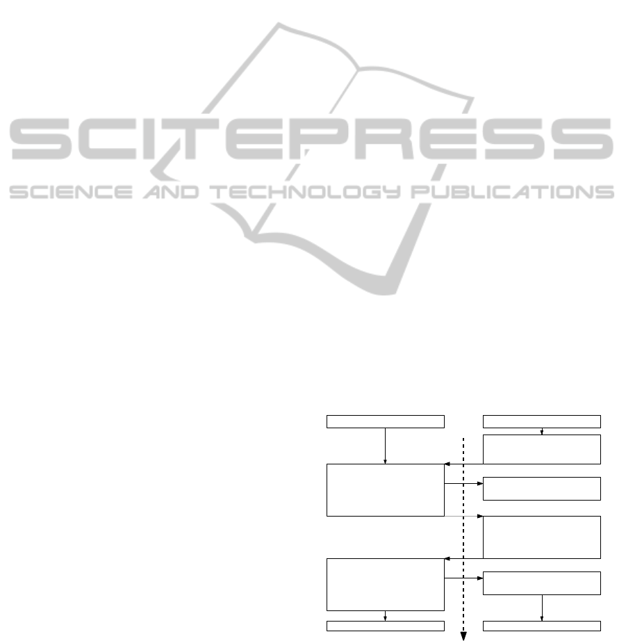
Figure 3 shows the handshake and the synchro-
nized execution of a stimulation sequence with two
pulses sent via the demultiplexer while no EMG
switch configuration is applied. The pulse frequency
within a sequence is fixed to 420Hz.
Stimulator
Demultiplexor
Communication (seq. conf.)
Communication (seq. conf.)
• reconfigure switches to
’Switch Configuration 1’
• set DMR high
• wait for DMR high
• set STIM low = active
• execute
’Pulse Configuration 1’
• set STIM high= inactive
• wait for STIM low
• set DMR low
• wait for STIM high
• reconfigure switches to
’Switch Configuration 2’
• set DMR high
wait for next Sequence Config.wait for next Sequence Config.
• wait for DMR high
• set STIM low = active
• execute
’Pulse Configuration 2’
• set STIM high= inactive
• wait for STIM low
• set DMR low
initial state STIM = high (inactive)
initial state DMR = low (not ready)
time
Figure 3: Execution of a sequence where two stimulation
pulses are generated and distributed over different switch
configurations.
COMBINED STIMULATION AND MEASUREMENT SYSTEM FOR ARRAY ELECTRODES
347
If more than one demultiplexer is connected to the
stimulator, the DMR signal will be set high by the
slowest demultiplexer indicating that all demultiplex-
ers are ready. The STIM signal is shared by all de-
multiplexer devices.
6 EMG MEASUREMENT
The measurement of EMG from a stimulated muscle
is of interest in order to detect residual volitional mus-
cle activity. The latter might be used to control the
stimulation. The use of array electrodes for stimula-
tion does not allow the placement of additional EMG
electrodes close to the virtual active electrode due to
the larger size of the array electrode. Therefore, EMG
measurement must be performed from virtual EMG
electrodes formed by elements of the stimulation ar-
ray. As shown in (Shalaby, 2011), EMG can be di-
rectly measured from the stimulation electrodes dur-
ing stimulation if the EMG amplifier is protected and
the electrodes are periodically discharged.
The EMG protection circuit consists of multiple
PhotoMOS relays and a high pass filter. The required
timing diagram for the PhotoMOS switches is shown
in Figure 4. During delivery of stimulation pulses two
X
last switch config. for stimulation
t
1
t
EMG switch configuration
next sequence
t
3
t
sc
t
2
t
f ilter_connected
t
4
t
f s
t
EM G_valid
PhotoMOS 1 on
t
5
PhotoMOS 2 on
1 21 2
Figure 4: EMG protection and discharging timing, t
1
. . . t
4
depend on sequence length and array setting.
PhotoMOS switches are used to mute the EMG mea-
surement (PhotoMOS 2 off). After the stimulation is
completed, another PhotoMOS relay short circuits the
electrodes over which the EMG signal is measured for
an user defined time interval to eliminate any resid-
ual charge on the electrodes (PhotoMOS 1 on). The
electrodes then are connected to the high-pass filter
(PhotoMOS 2 on) which reduces low frequency dis-
turbances. The actual EMG measurement however is
performed by an external standard EMG amplifier.
The duration of the short circuit t
sc
is between 7
and 8ms. The high-pass filter needs the time t
fs
to set-
tle. Thus it is best to activate PhotoMOS 2 as early as
possible to maximize the valid EMG recording time
t
EMG
valid
. The stimulation-induced EMG response
(M-wave) falls together with the filter transients and
is excluded from the EMG measurement. Basically,
only volitional muscle activity is captured in the time
interval t
EMG
valid
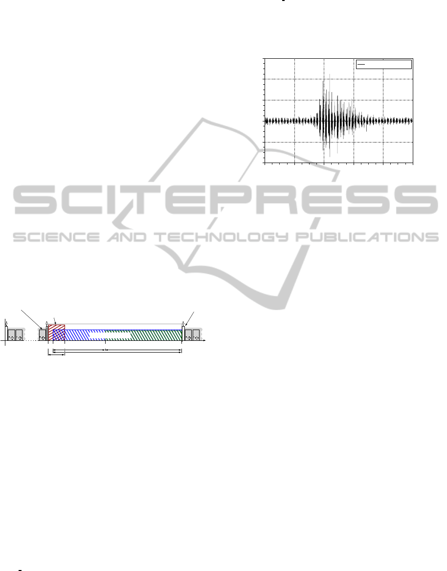
. An EMG recording of the wrist
extensor under stimulation is shown in figure 5. Parts
of the EMG recording which are disturbed by filter
transients are already blanked in the shown EMG sig-
nal.
41.0 41.5 42.0 42.5 43.0 43.5
−1000
−500
0
500
1000
1500
time [s]
EMG [uV]
EMG under stimulation
Figure 5: EMG recording of volitional muscle activity
from the stimulated wrist extensor (pulse width 100µs,
I=15mA).
7 CONCLUSIONS
The system enables researchers and health profes-
sionals to use array electrodes without large effort.
The developed software simplifies the setup of com-
plex stimulation patterns and permits a straightfor-
ward integration of array electrodes into existing
stimulation setups. Parameters like pulse widths,
stimulation currents or demultiplexer configurations
can be adjusted in real-time. The demultiplexer sup-
ports array sizes up to 60 elements for the active elec-
trode and up to 4 elements for the indifferent elec-
trode. The small switch module can be placed near
to the array electrode, avoiding extensive wiring. The
ability to measure volitional EMG signals from a pair
of virtual electrodes makes array electrodes usable for
diagnostics or control applications. In future work,
the remaining problem of filter transients must be
solved by introducing digital filters and including the
EMG amplifier into the switch module.
REFERENCES
Azevedo-Coste, C., Bijelic, G., Schwirtlich, L., and
Popovic, D. (2007). Treating drop-foot in hemi-
plegics: the role of matrix electrode. In 11th Mediter-
ranean Conf. on Medical and Biomedical Eng. and
Computing 2007, pages 654–657.
Keller, T., Lawrence, M., Kuhn, A., and Morari, M. (2006).
New multi-channel transcutaneous electrical stimula-
tion technology for rehabilitation. In Conf Proc IEEE
Eng Med Biol Soc., volume 1, pages 194–197.
BIODEVICES 2012 - International Conference on Biomedical Electronics and Devices
348

O’Dwyer, S. B., O’Keeffe, D. T., Coote, S., and Lyons,
G. M. (2006). An electrode configuration technique
using an electrode matrix arrangement for FES-based
upper arm rehabilitation systems. Med Eng Phys,
28(2):166–176.
Popovi-Bijeli, A., Bijeli, G., Jorgovanovi, N., Bojani, D.,
Popovi, M. B., and Popovi, D. B. (2005). Multi-field
surface electrode for selective electrical stimulation.
Artificial Organs, 29(6):448–452.
Shalaby, R. (2011). Development of an EMG detection sys-
tem for the control of FES in neurological rehabilita-
tion. PhD thesis, Technische Universit¨at Berlin.
COMBINED STIMULATION AND MEASUREMENT SYSTEM FOR ARRAY ELECTRODES
349
