
AN INTEGRATED ACTIVE-RC POWERLINE NOTCH FILTER
FOR BIOPOTENTIAL ACQUISITION DEVICES
Hussain Alzaher, Noman Tasadduq and Yaqub Mahnashi
Electrical Engineering Department, King Fahd University of Petroleum & Minerals, 31261, Dhahran, Saudi Arabia
Keywords: Notch filter, CMOS Analog integrated circuits, Biomedical.
Abstract: An integrable 60Hz continuous time active-RC notch filter is presented. This is made possible through
replacing passive resistors by R-2R ladders providing area saving of approximately 120 times. The proposed
filter is to be embedded into instrumentation amplifier for biopotential measuring devices. Simulation
results of a fully differential 4
th
-order filter show notch depth of 68dB and THD of better than -70dB while
consuming 18μW.
1 INTRODUCTION
Very low frequency filters has wide range of
applications in biomedical signal processing (Li,
Poon and Zhang, 2010). In particular, it is desired to
eliminate power line frequency disturbance of 60Hz
(50Hz in Europe) from the measured signal using
notch filters. Power line interference is the most
common problem in the detection and processing of
biopotential signals (Qian et al., 2005; Ling et al.,
2007; Ling and Luo, 2008; Ma et al., 2009; Ma et
al., 2009). Despite the use of differential
amplification methods and active body potential
driving to eliminate the common-mode signals, the
line frequency interference occurs in the important
frequency range where biopotentials and other
physiological signals have most of their energy. This
is the case in electroencephalogram (EEG),
electrocardiogram (ECG), and electromyogram
(EMG) recordings. Power line interference has
considerable effect and plays an important part on
the quality of these signals.
In order to utilize very large-scale integration
(VLSI) techniques in biomedical instrumentation,
implementation of this 60Hz notch filter in a single
integrated chip (IC) is required. This has been a
challenging design problem due to the difficulty in
developing efficient methods to achieve large time
constant using integrated passive elements. Several
different techniques have been used to circumvent
this problem. A 5
th
order elliptic lowpass notch filter
using LC ladder approach based on OTAs was
reported in Qian et al. (2005), Ling et al. (2007) and
Ling et al. (2008). Current division and current
cancellation techniques are employed for the
designing ultra-low (in order of nA/V or pA/V)
transconductance with transistors working in weak
inversion region for low power operation enabling
the use of small capacitor values. The single ended
filter of Qian et al. (2005) is fabricated in 0.35μ
CMOS process, and achieves 66dB notch
attenuation at 50Hz with a stopband attenuation of
36dB above 50Hz, while consuming total power of
11.1μW. But it is associated with THD of -50dB for
an input voltage of 25mV and frequency of 8Hz.
Whereas, the filter of Ling et al. (2007) and Ling et
al. (2008) is simulated using 0.6m CMOS process,
and achieves 58.5dB attenuation at 50Hz with a
stopband attenuation of 32dB above 50Hz.
Switched-capacitor (SC) based low frequency
filters in modern IC processes suffer from leakage
problem and hence the sample-hold circuits of the
switched based topologies are unsuitable for
applications requiring large time constants (of the
order of millisecond or more) (Li et al., 2010). On
the other hand, gm-C based filters are usually
associated with limited linearity. In general, design
of OTAs turned to be challenging under constrains
of low-noise performance, dynamic range and chip
area. This is because a small transconductance
requires reducing the biasing current which
automatically results in smaller input linear range
and more noise. The low linearity associated with
the use of transconductors is overcome by a rare
65
Alzaher H., Tasadduq N. and Mahnashi Y..
AN INTEGRATED ACTIVE-RC POWERLINE NOTCH FILTER FOR BIOPOTENTIAL ACQUISITION DEVICES.
DOI: 10.5220/0003789400650070
In Proceedings of the International Conference on Biomedical Electronics and Devices (BIODEVICES-2012), pages 65-70
ISBN: 978-989-8425-91-1
Copyright
c
2012 SCITEPRESS (Science and Technology Publications, Lda.)

active RC opamp based filter presented in Casper,
Comer and Comer (1999). It utilizes time constant
multiplier (TCM) circuit to attain large time
constants using resistors and capacitors that can be
integrated. The filter typically exhibits Q of ½, and a
notch depth of 45dB. But the suggested circuit uses
10 opamps and thus the power consumption is
expected to be large.
This paper presents a new CMOS circuit
technique for implementing a continuous time 60Hz
notch filter suitable for integration. A new filter
design approach maintaining the advantages of
existing techniques while providing improved
characteristics is developed. The following section
presents the proposed filter. Design of the different
components of the filter is presented in section 3.
Simulation results are given in section 4.
2 PROPOSED APPROACH
Active-RC filters inherently exhibit high dynamic
ranges and the required large time constants can be
realized with the help of R-2R ladders (usually used
in data converters). The R-2R ladder, shown in
Figure 1, can be considered as a digitally
programmable resistor given by:
eq
V
R
R
I
β
==
where
1
1
2
n
i
i
i
b
β
−
=
=
∑
(1)
where b
i
, equaling 0 or 1, is the i
th
bit in an n-bit
digital control word. However, the optimum use of
R-2R ladders in this application occurs when their
configurations result in the largest possible
equivalent resistance, between the input terminal of
a ladder and virtual ground.
The maximum equivalent resistance, of an R-2R
ladder is achieved only when the least significant
branch current (I
LS
) is connected to the virtual
ground (i.e b
n
=1 and others b
i
=0). Therefore, the
maximum equivalent resistance
ma x
2
n
RR=
can be
increased by increasing the size of the ladder (n)
and/or the value of the basic resistance R. In this
case there is no need to use any switch. Also, since
the value of I
LS
is independent of the 2R resistance
connected with b
1
, it can be removed to save more
area. Thus, the total area needed to make an n-bit R-
2R reduces to R
tot
=(3n-1)R. The relative saving in
area achieved through the use of a R-2R ladder is
proportional to R
max
/R
tot
=2
n
/(3n-1). Therefore, it can
be seen that this saving is independent of R values
and it improves considerably as n increases. For
example, saving in area of approximately 11, 20, 35,
117 and 400 times is achieved for n= 8, 10, 12, and
14, respectively.
In conventional use of R-2R in data conversion,
the main error sources are due to the switch-on
resistances which are avoided in our proposed
solution. The R-2R ladder can be incorporated by
replacing the passive resistors of the original filter as
long as these resistors are connected to virtual
ground, which simulates the proper operating
condition of the R-2R ladder. The Tow-Thomas
(a)
(b)
Figure 1: R-2R ladder (a) conventional (b) for this application.
BIODEVICES 2012 - International Conference on Biomedical Electronics and Devices
66
filter topology exhibits this feature and can be
designed for pre-required gain and Q and hence, is
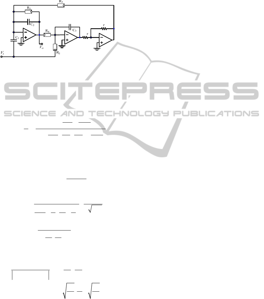
selected for this application. The proposed filter is
shown in Figure 2.
Figure 2: Single ended version of the proposed filter.
Assuming finite opamp gains of A and with the
practical convenient choice of
R
2
=R
3
=R
4
=R;
C
1
=C
2
=C; R
1
=qR non-ideal analysis of the circuit
of Figure 3 yields the following transfer function:
2
2
33
()
2
2
33
21
()
212 1
o
non ideal
i
ss
CRA CCR
V
Ts
V
ss
CRA CqR CRA CCR
−
⎛⎞
++
⎜⎟
⎝⎠
=≈−
⎛⎞⎛⎞
++++
⎜⎟⎜⎟
⎝⎠⎝⎠
(2)
The non-ideal parameters of the filter will be given
by:
22
()
2
3
1
ononideal o
CC R
ωω
−
≈=
(3)
()
3
3
3
11
1211
1
2
1(1)
non ideal
Q
RCC
CqR A C C
Q
qC
AC
−
⇒≈ ×
⎛⎞
++
⎜⎟
⎝⎠
=
++
(4)
The depth of the notch will be given by:
3
()
33
1
11
2
()
1( )
non ideal o
C
A
p
Cq
Tj
CC
A
CQ C
ω
−
⎛⎞
==++
⎜⎟
⎝⎠
=+ +
(5)
Therefore, p can be increased by increasing the
ratio C
3
/C, A and/or decreasing Q. In practice and
for any notch filter there is inverse relation between
the depth of the notch p and Q. This result is clearly
shown in (5). On the other hand, it is clear from (4)
and (5) that as A increases p will increase and Q
(non-
ideal)
will slightly increase to approach its ideal value.
Also, increasing the ratio C
3
/C will have more
impact on increasing p than decreasing Q. Hence it
is advantageous to select C
3
/C as large as possible.
Mismatches of passive resistance within each
ladder will cause error in value of R
eq
. This would
cause the notch frequency to deviate from its
nominal value. Thus, some sort of fine tuning is
needed to compensate for passive elements
variation. Considering (3)-(4), it can be seen that ω
o
can be tuned without disturbing Q via adjusting
either all resistors R’s and/or all capacitors
simultaneously. Fine tuning can be achieved using
resistors and/or capacitor matrices. Three 6-bit
capacitor matrices are adopted to tune the filter
notch frequency. Tuning range from 40Hz to 80Hz
for notch frequency is selected. This allows for
compensating for ±33.3% variation in nominal
frequency, achieving resolution accuracy of
approximately 1% (0.6Hz).
3 IMPLEMENTATION
Fully integrated biomedical systems incorporate
fully differential architectures to enhance the
performance in terms of supply noise rejection,
signal swing, and harmonic distortion and also to
reduce the effect of coupling between various
blocks. Also in fully differential structure, there is
no need for the inverter since signals can be inverted
by means of proper cross coupling between the
positive and negative paths. A fully differential
version of a two stage class AB opamp is shown in
Figure 3 (Morillo et al., 2006). Since both input and
output stages are class-AB, it can work with very
low biasing currents, hence providing very low
power solution.
The opamp was simulated using supply voltages
of ±0.75V. The opamp was optimized to achieve at
least 70dB gain with minimum biasing current while
deriving load capacitances of 50pF and resistances
of 80kΩ. This load represents the most stringent
load (C
3
and ladder of R
3
)
derived by the second
opamp. The optimization process has resulted in a
gain of 72dB when the opamp is biased with a total
current of 3µA. The opamp is compensated to have a
phase margin of better than 65
o
resulting in a unity
gain frequency (f
t
) of 90kHz.
The other major step in the implantation phase is
to decide on the ladder size and value of passive
AN INTEGRATED ACTIVE-RC POWERLINE NOTCH FILTER FOR BIOPOTENTIAL ACQUISITION DEVICES
67
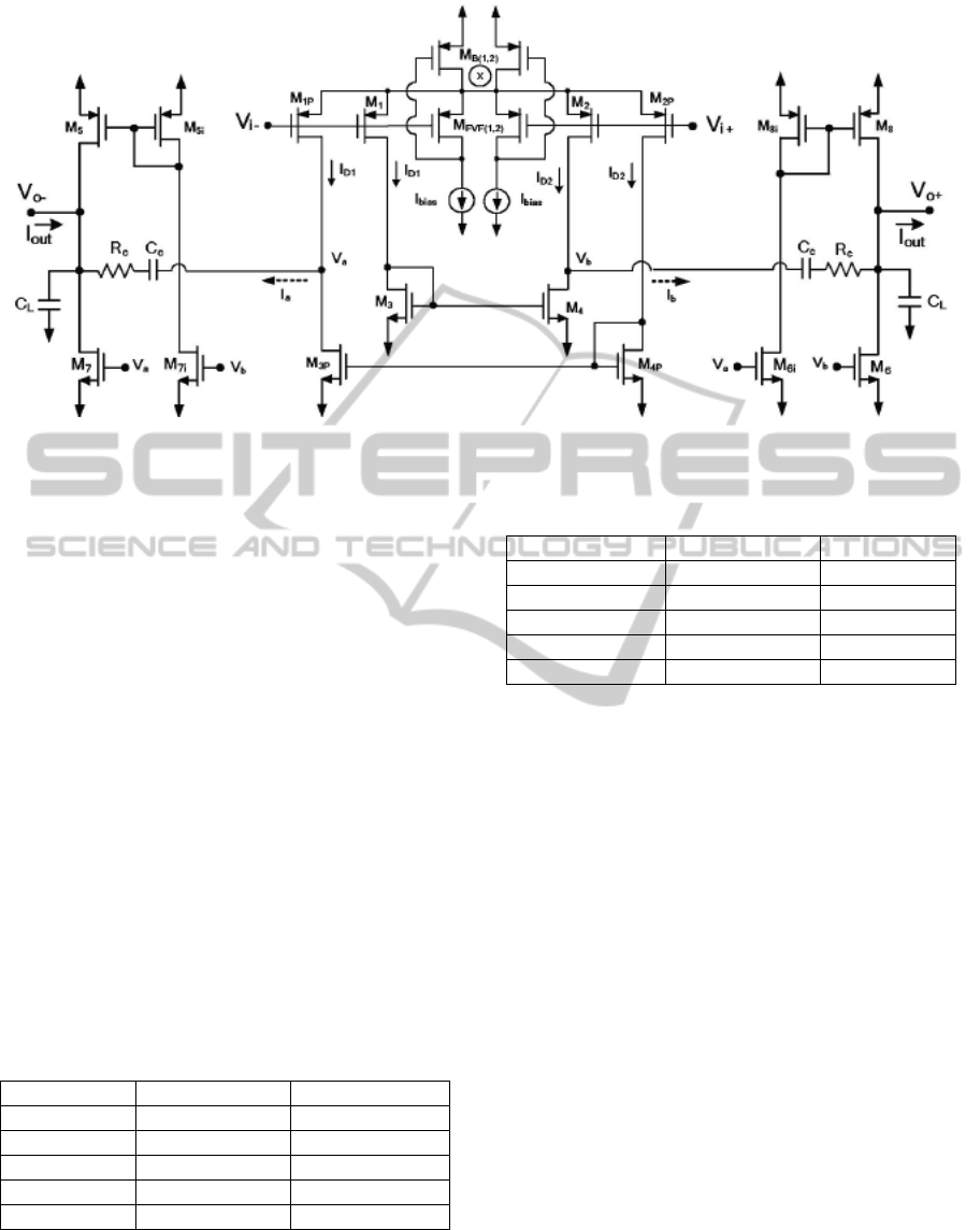
Figure 3: A two stage class-AB opamp (Morillo et al., 2006).
components required to develop the proposed filter.
The value of CR required to achieve 60Hz notch
frequency can be determined for a specific ladder
size and C
3
. Assuming maximum capacitance of
50pF for C
3
and R=40kΩ, Table 1 gives the required
value of C=C
1
=C
2
for several ladder sizes. Also, the
value of qR for maintaining Q=1/2 is given.
It is found that the minimum area is achieved for
the case of 12 bits wherein the passive components
are C
3
=50pF, C
1
=C
2
=5.2pF, R=40kΩ and qR=62kΩ.
Table 2 shows the several different values of C
3
and
C for achieving notch frequency of 60Hz when
using 12 bit ladders of R=40kΩ. Also, it gives the
required values of qR to adjust Q to ½. Effect of
increasing C
3
to improve the notch depth for a fixed
Q of ½ is verified through simulation. It has been
found that as C
3
is increased, more depth is attained.
In fact selecting C
3
=50pF (assuming maximum
capacitance of 50pF) shows a 10dB improvement in
the notch depth compared with the case of equal
capacitors.
Table 1: Passive component values as function of various
ladder sizes.
C
3
C=C
1
=C
2
qR
50pF 5.2pF 62kΩ
40pF 6.5pF 49.6kΩ
30pF 8.7pF 37.2kΩ
20pF 13pF 24.8kΩ
16.1pF 16.1pF 20kΩ
Table 2: Several possible values of C
3
for Q=1/2,
R=40kΩ.
C
3
C=C
1
=C
2
qR
50pF 5.2pF 62kΩ
40pF 6.5pF 49.6kΩ
30pF 8.7pF 37.2kΩ
20pF 13pF 24.8kΩ
16.1pF 16.1pF 20kΩ
4 SIMULATION RESULTS
Post layout simulations are carried out using 0.18μ
CMOS technology for the proposed filter. The filter
uses a supply voltage of ±0.75V while consuming
total power of 9μW while occupying an area of 0.25
mm
2
. The R
1
ladders were made up of 14-bit, the
additional 2 bits are employed to allow
programming the quality factor of the filter from 1/2
to 2. Post layout simulation results show that the
filter achieves notch attenuation of 43dB and Q of
approximately ½ as shown in Figure 4. The notch
frequency can be tuned from approximately 40Hz to
80Hz which represents more than ±33% variations
of the nominal value of 60Hz as shown in Figure 4
using capacitor arrays. Also, it was found that the
gain of the high passband filter is flat for frequencies
up to approximately 100kHz because of the
relatively low unity gain frequency of the opamp.
Two sections of the filter were connected in cascade
to realize 4th-order design in order to enhance the
notch depth. Simulation results are shown in Figure
5 where -78dB notch depth is recorded.
BIODEVICES 2012 - International Conference on Biomedical Electronics and Devices
68
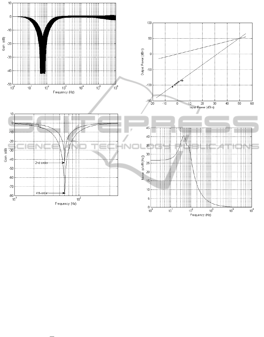
Figure 4: Frequency response of the proposed filter.
Figure 5: Simulation results of the 2
nd
-oder filter and
cascaded 4
th
-order fillter.
It is found that the maximum output signal peak
to peak voltage before clipping is approximately
1.2V. Also, total harmonic distortion (THD) of
better than -70dB is achieved. The third-order
intermodulation distortion is found using two tone
tests with frequencies at 40Hz and 50Hz. It is found
that the filter exhibits IIP3 of about 49dBm as shown
in Figure 6. The input referred noise root spectral
density of the filter is shown in Figure 7. The total
noise power is found to be approximately 280µV (-
58dBm) over low frequency passband (up to 60Hz).
The corresponding spurious-free dynamic range
(SFDR) can be found from the IIP3 and noise power
(N):
2
(3 )
3
SFDR IIP N=−
(6)
This leads to SFDR of approximately 71.3dB
(referenced to 50Ω).
Figure 6: Estimation of IP3 using two tone tests.
Figure 7: Input referred noise root spectral density.
In addition, when Q=2 a notch depth of -36dB is
achieved. It is found that by cascading two of these
sections the low side passband frequency extends up
to 60Hz and the notch depth becomes about -68dB.
Table II shows a summary of the performance of the
proposed filter along with various filters in the
literature.
It is clear that the proposed filter achieves much
lower power consumption compared with that of Ma
et al. (2009). Also, it manages to show 20dB
improvement over its counterpart of Qian et al.
(2005) in terms of THD. For the case of Q=1/2, the
4
th
-order filter provides 12dB notch depth more than
Qian et al. (2005) while using 15% less power (since
single-ended filters typically often require one-half
the power of their fully differential counterparts).
AN INTEGRATED ACTIVE-RC POWERLINE NOTCH FILTER FOR BIOPOTENTIAL ACQUISITION DEVICES
69

Table 3: Summary of various filters used for biomedical applications.
Ref. Qian et al. (2005)
Ling et al. (2007)
Ling et al. (2008)
Ma et al. (2009) This Work
Tech.
0.35μ
CMOS
0.6μ
CMOS
90n
CMOS
0.18μ
CMOS
App. EEG EEG
Power Line
Interference
Power Line
Interference
Type LPN LPN Notch Notch
Order 5 5 - 4
Pole/center
frequency
30-67Hz 30-67Hz 50 to 60Hz 60Hz
Power/
Supply Voltage
11μW/
±1.5V
-
75μW/
3V
18μW/
±0.75V
Structure OTA-C OTA-C Chopper Opamp
THD -50dB - - -70dB
Results Experimental Simulation Simulation Simulation
5 CONCLUSIONS
A new fully integrated 60Hz notch filter is proposed.
R-2R ladders are adopted to allow the realization of
large time constant in small area and they are
employed in a proper filter topology. The proposed
filter can be easily reconfigured as lowpass,
bandpass or highpass filter to meet the specification
of other biomedical applications. Simulation results
of the filter based on the low-power opamp show
comparable power consumption with the gm-C
based filter while achieving better linearity.
ACKNOWLEDGEMENTS
The authors would like to thank King Abdulaziz
City for Science and Technology (KACST) for the
financial support (Project No: AT-29-99).
REFERENCES
Li, Y., Poon, CY., Zhang, Y., 2010. Analog Integrated
Circuits Design for Processing Physiological Signals.
IEEE Reviews on Biomedical Eng., 3, 93-105.
Qian, XB., Xu,YP., Li, XP., 2005. A CMOS Continuous-
Time Lowpass Notch Filter for EEG Systems. Analog
Integrated Circuits Signal Processing. 44(3), 231–238.
Ling, C., Ye, P., Liu, R., Wang, J., 2007. A Low-Pass
Power Notch Filter Based on an OTA-C Structure for
Electroencephalogram. Proc. International Symposium
on Intelligent Signal Processing and Comm. Syst.
China, 451-453.
Ling, C., Luo, M., 2008. Research of the ASIC Used for
EEG Signal Detecting. Int. Conf. on Anti-
counterfeiting, Security and Identification (ASID)
China, 316-319.
Ma, C., Mak, P., Vai, M., Mak, P., Pun, S., Feng, W.,
Martins, RP., 2009a. Frequency-Bandwidth-Tunable
Powerline Notch Filter for Biopotential Acquisition
Systems. Electronics Letters, 45(4), 197-199.
Ma, C., Mak, P., Vai, M., Mak, P., Pun, S., Feng, W.,
Martins, R P., 2009b. A 90nm CMOS Bio-Potential
Signal Readout Front-End with Improved Powerline
Interference Rejection. IEEE Int. Symp. Circuits Syst.
(ISCAS), 665-668.
Casper, BK., Comer, DJ., Comer, DT., 1999. An
Integrable 60-Hz Notch Filter. IEEE Trans. on circuits
and systems-II, 46(1), 74-77.
Lopez-Morillo, E., Carvajal, RG., ElGimili, H., Lopez-
Martin, A., Ramirez-Angulo, J., Rodriguez-Villegas,
E., 2006. A very low-power class AB/AB op-amp
based sigma-delta modulator for biomedical
applications. Midwest Symposium on Circuits and
Systems (MWSCAS'06), 2, 458–462.
BIODEVICES 2012 - International Conference on Biomedical Electronics and Devices
70
