
MULTI-SOURCE ENERGY HARVESTING POWER GENERATORS
FOR INSTRUMENTED IMPLANTS
Towards the Development of a Smart Hip Prosthesis
M. Soares dos Santos
1
, Jorge A. F. Ferreira
1
, A. Ramos
1
, Ricardo Pascoal
1
, Raul Morais dos Santos
2
,
Nuno M. Silva
2
, Jos´e A. O. Sim˜oes
1
, M. J. C. S. Reis
2,3
, Camila N. Boeri
1
, Ant´onio Festas
1
and Paulo M. Santos
2
1
Department of Mechanical Engineering, Centre for Mechanical Technology & Automation, University of Aveiro,
Campus Universit´ario de Santiago, 3810-193, Aveiro, Portugal
2
Engineering Department, University of Tr´as-os-Montes e Alto Douro, Quinta de Prados, 5001-801 Vila Real, Portugal
3
IEETA - Instituto de Engenharia Electr´onica e Telem´atica de Aveiro/UTAD, 5001-801 Vila Real, Portugal
Keywords:
Smart hip prosthesis, Electric bio-generator, Energy harvesting, Self-powered systems, Biomedical implants.
Abstract:
Very few developments have been done to provide electric power supply of instrumented hip prosthesis.
Actually, vibration-powered generators are the most appropriate mechanisms for this kind of application’s
environment. This paper describes the first attempt to develop the concept of energy harvesting from multiple
energy sources applied in the same hip implant. Exploiting the potential of the three angular movements over
the femoral component, namely in the abduction-adduction, flexion-extension and inward-outward rotation
axes, three inboard vibration-based mechanisms were developed in order to ensure electric power supply from
multiple energy sources. A total of 53.7 µJ/s was harvested by a translation movement-based electromagnetic
energy generator when a sinusoidal function with an amplitude of 40 mm and a frequency of 4 Hz was applied.
A rotation movement-based electromagnetic energy generator has harvested 0.77 µJ/s when a sinusoidal
function with an amplitude of 60 and a frequency of 2.5 Hz was used. The piezoelectric energy harvester has
achieved 0.6 µJ/s with the application of a sinusoidal function with an amplitude of 200 N and a frequency of
4 Hz. Besides, its ability of being fully autonomous, operating without expiry and maintenance, while offering
safety during its entire lifetime are relevant features. This paper should provide the basis for the development
of smart hip prosthesis with the ability to fix the aseptic implant loosening problem.
1 INTRODUCTION
Loosening of the prosthetic stem and cup is a
serious complication of the Total Hip Replacement
Arthroplasty (THR), being referred that more than
80% of the non-success surgical procedures are due
to implant loosening (Alpuim et al., 2008). Generally,
the revision rate is about 10% in the case of prosthesis
implanted 10 years before. However, a growth of
about 100% is estimated in the revision procedures in
the EUA by 2030 (Kurtz et al., 2007). The progressive
bone loss surrounding the implant is considered the
main cause of the THR failure. The revision surgeries
are more complex, more expensive, more painful and
present a non-success rate higher than primary THRs.
Taking into account the increase of the average life
expectancy and the number of THRs applied in young
patients, the development of durable hip prosthesis
is imperative. The current instrumented prosthesis
proposals have only been designed to collect forces
and kinematics data acting in vivo, in order to promote
the continuous optimization of such implants (Damm
et al., 2010; Heinlein et al., 2009; Westerhoff et al.,
2009; Rohlmann et al., 2008; Heinlein et al., 2007;
Graichen et al., 1999). The expertise of these implants
does not allow continuous real-time problem solving,
but only provides data to support new research. To
avoid the need of revision surgeries, a new concept
of prosthesis is emerging to diagnose and contribute
to fix the loosening problem: methodology based on
the use of mechanical micro-stimulation to promote
the remodelling of the bone surrounding the implant,
considering that bone resorption and deposition are
strongly related to mechanical stimuli (Frias et al.,
71
Soares dos Santos M., A. F. Ferreira J., Ramos A., Pascoal R., Morais dos Santos R., M. Silva N., A. O. Simões J., J. C. S. Reis M., N. Boeri C., Festas
A. and M. Santos P..
MULTI-SOURCE ENERGY HARVESTING POWER GENERATORS FOR INSTRUMENTED IMPLANTS - Towards the Development of a Smart Hip
Prosthesis.
DOI: 10.5220/0003792100710081
In Proceedings of the International Conference on Biomedical Electronics and Devices (BIODEVICES-2012), pages 71-81
ISBN: 978-989-8425-91-1
Copyright
c
2012 SCITEPRESS (Science and Technology Publications, Lda.)
2010). Therefore, the smart hip prosthesis should
allow the osteointegration monitoring in the critical
regions of the bone-implant interface (self-diagnosis
function) and mechanically micro-stimulate the local
region under loosening, in order to remodel the bone
surrounding the hip prosthesis (adaptive function).
The failure detection in hip implants and the regions
of the implant where it occurs with time are
currently being studied (Marschner et al., 2009;
Rowlands et al., 2008; Alpuim et al., 2008;
Puers et al., 2000). To yield an architecture to
accommodate energy harvesting systems, activation
circuits to wake up deep sleep electronics, who
relies on batteries to operate, have been developed
to instrument hip prosthesis (Morais et al., 2009),
but they have been powered inductively by external
coils (Morais et al., 2009; Marcelli et al., 2007).
The detection/micro-stimulation system’s operation
demands for an autonomous bio-generation system
that electrically must supply not only the telemetry
but also the mechanical bio-stimulation systems.
Only a vibration bio-generator, designed using the
electromagnetic principle, was proposed to supply
smart hip prosthesis (Morais et al., 2011; Morais
et al., 2010), but the multi-source methodology
of the vibration-based energy harvesting system in
the same hip implant was not approached. When
the availability of the electric power supply is
jeopardized, the reliability of the power supply
mechanism decreases. This paper reports an electric
vibration-based bio-generator from multiple energy
sources for smart hip prosthesis. It is composed of
a piezoelectric and two electromagnetic generation
mechanisms in a same hip joint prosthesis. This
methodology should serve as a reference for future
work on smart hip prosthesis with the purpose of
avoiding revision procedures.
This paper is organized as follows: after this
introductory section, the three generators that make
up the prototype are described, from the theoretical
background to the characterization of the practical
design. The simulated and experimental generation
results are presented and discussed in section 3.
Finally, in section 4 conclusions and final remarks of
this work are given.
2 MULTI-SOURCE ELECTRIC
POWER BIO-GENERATORS
2.1 Hip Prosthesis Prototype
To validate the multi-source self-powered electrical
supplying methodology, the commercially available
Metabloc
T M
straight stem system (Zimmer
Corporate, Warsaw, Indiana, EUA) was used as
a model to design a passive hip prosthesis prototype.
The size 10 of this stem system was modified to
obtain a hollow hip prosthesis prototype. The fatigue
resistance of instrumented hollow bone implants has
already been guaranteed by fatigue tests (Westerhoff
et al., 2009; Heinlein et al., 2007). Figure 1 focuses
on the full active prototype of the hip prosthesis
with vibration-based electric power bio-generators.
The electromagnetic-based transduction mechanisms
were positioned respectively in the body and
in the upper half of the head, whereas the
piezoelectric-based transducer was mounted in
the lower half of the femoral head.
Figure 1: Electric power bio-generators from multiple
energy sources for a hip prosthesis prototype.
2.2 Energy Harvesting Systems
There are many possibilities to harvest electric energy
from the surrounding environment. Biofuel Cells,
magnetic induction, thermoelectric and vibration are
some of the main sources used to harvest energy.
High-quality articles and books have been published
about this subject and highlight how important such
mechanisms can be in the development of smart
bone implants (Lu et al., 2011; Ka´zmierski and
Beeby, 2011; Carmo et al., 2010; Zhu et al., 2010;
Beeby and White, 2010; Westerhoff et al., 2009;
Priya and Inman, 2009; Kerzenmacher et al., 2008;
Wei and Liu, 2008). Vibration-based generation is
currently the most appropriate solution to convert
mechanical vibrations into electrical energy in order
to electrically supply the active elements of the smart
hip prosthesis (Morais et al., 2011; von B¨uren et al.,
2006).
BIODEVICES 2012 - International Conference on Biomedical Electronics and Devices
72

2.3 Translation Movement-based
Electromagnetic Energy Harvester
Using mechanical accelerations, obtained from
human gait activities, as the energy source for energy
scavengers, an electromagnetic power transducer
(TEEH) was designed in the body of the hip
prosthesis to take advantage of the movements in
the abduction-adduction and flexion-extension axes
through the hip joint (Winter, 2009; Whittle, 2007).
2.3.1 Theory Background
The principle of the electromagnetic generation of
electric energy is based on Faraday’s law, who
formulated that the relative movement of a coil
within a constant magnetic field, generated by a
permanent magnet, induces an electromotive force
in that coil through the change in the magnetic flux
(Ida, 2004). The theory of the linear behaviour
of the generality of the vibration-based generators,
is already well developed (Ka´zmierski and Beeby,
2011; Priya and Inman, 2009; Cook-Chennault et al.,
2008; Gilbert and Balouchi, 2008; Beeby et al.,
2006). As with inertial resonant generators, they
use mechanical movement as the physical condition
to harvest electric energy. Linearly, they can be
modelled as a single degree-of-freedom mechanical
damping system represented by a second-order
mass-spring-damper system, because the damping
mechanism is proportional to the kinetic energy. The
general resonant generator theory states that:
(i) The mechanical input is the external mechanical
vibration (represented below by y t , as in figure
2). Generally, the human gait analysis has shown
frequency movements between 0.5 Hz and 2 Hz.
The international ISO 14242 standard specifies, for a
frequency of 1 Hz, a pattern of the relative angular
movement between articulating components and a
pattern of the applied force for orbital bearing type
wear testing machines of hip prosthesis. However, the
real loading and displacement parameters are much
more complex than the standardized ones, involving
highly nonlinear functions with several parameters,
such as the frequency of movements, weight, age,
bone structure, health conditions, type of activity,
muscle acceleration imposed by the patient’s activity,
among others;
(ii) The mechanical structure can be modelled as an
inertial frame (fixed referential) where a suspended
seismic mass is attached, representing a magnet,
coupled to a spring, which in turn is coupled to
a damping element, representing the sum of the
comprising parasitic losses and the electrical energy
extracted by the transducer (Beeby et al., 2006).
External movements are transmitted by the inertial
frame, producing a relative displacement z
t between
the mass and the frame (as represented in figure
2), which is the amount of mechanical vibration to
be converted into electric energy. The differential
equation of this second order system is described as:
m
z t cz t kz t my t (1)
in which m is the seismic mass, k the stiffness of the
spring and c is the damping coefficient. When this
damping system is excited by an external sinusoidal
vibration y
t Ysin ωt , the solution of (1) is given
by:
z t
ω
2
ω
2
n
ω
2
2
2ζω
n
ω
2
Ysin ωt arctg
2ζω
n
ω
ω
2
n
ω
2
(2)
in which ω
n
k m is the natural frequency and
ζ
c 2mω
n
is the total damping ratio of the
resonant generator system. The damping coefficient
resulting from electromagnetic transduction c
e
can be approximately achieved (considering only
movements from high to zero magnetic fields (Beeby
et al., 2006)) by:
c
e
NlB
2
R
load
R
coil
jωL
coil
(3)
l is the perimeter of one turn of the coil, N is the
number of turns of the coil, B is the flux density to
which the coil is subjected, and R
load
, R
coil
and L
coil
are respectively the load resistance, coil resistance
and coil inductance;
(iii) The average power output, applying y
t
Ysin ωt , is defined as:
P t
mζ Y
2
ω
3
Ω
3
1 Ω
2
2
2ζ Ω
2
(4)
in which Ω
ω ω
n
is a dimensionless parameter
that denotes the difference between the real frequency
and the natural frequency of the generator system.
Considering V
2PR, the average voltage output
can be estimated by:
V
t
BlYω
3
ω
2
n
ω
2
2
2ζω
n
ω
2
(5)
(iv) In order to optimize the generation of electric
power, the frequency of the hip kinematics must
match the resonant frequency of the generator.
Taking into account that the external vibration,
which is the input of the bio-generator of smart hip
prosthesis, cannot be controlled by the generator,
the matching must be performed by tuning the
resonant frequency of the generator. Although the
MULTI-SOURCE ENERGY HARVESTING POWER GENERATORS FOR INSTRUMENTED IMPLANTS - Towards
the Development of a Smart Hip Prosthesis
73

vibration-based transducers are currently considered
the best methodology to develop bio-generators from
human gait at hip localization, a continuous matching
of the frequency range of the hip kinematics of
patients with the resonant frequency of the generator
is a difficult task to do, because the duration and
frequency of every-day human activities and the
frequency of the activity itself are unpredictable
(Morlock et al., 2001). With constant resonant
frequency, the best result is obtained when the human
being controls the duration and frequency of the
activity. Even so, a perfect match is not achievable.
This linear model does not take into account
the real mechanical input data (translational and
rotational movements of the hip joint), and several
other forces acting in the system, such as friction and
gravity forces. However, it is a solid basis to start the
study of the dynamic behaviour of this kind of system.
2.3.2 Permanent Magnet Vibration Power
Generator Prototype
The generator prototype is composed of an extension
coil spring (K 2.45 N/m, 5 mm of diameter, 10
mm of steady-state length and 0.2 mm
2
of wire
section) and two neodymium disc magnets N35 (6
mm of diameter, 6 mm of height, 1.21 g of weight
and 1.22 T of magnetic field), which are suspended
inside a Teflon tube (c
m
0.04) where enamelled
copper wire (0. 1 mm of diameter, 27 mm of length
and 1.72
10
8
Ωm of electrical resistivity) was
wound (N 2000 turns, 124.4 Ω of total wire
resistance), which in turn was attached to the hip
prosthesis fixture. The coil and the prosthesis make
up the inertial frame. Two magnets were used to
make larger the separation between the poles of the
magnet, in order to ensure that the magnetic field
lines were nearly perpendicularto the wiring direction
of the coil, which leads to better results, according
to Morais at al. (2011). Figure 2 shows a 2-D
representation of this bio-generator. The coil was
located as close as possible to the magnetic field lines
in order to maximize the change in magnetic flux
and reduce friction between the tube and the magnet.
Taking into account the volume restrictions inside the
prosthesis, the coil was lengthened to maximize the
number of coil turns. The spring was chosen to be
nonferrous to avoid the induction of a current into
the spring from the magnetic field generated by the
magnet, preventing magnetic attraction between them
that would stop the relative movement between the
magnet and the coil during the human gait. With this
design, the natural frequency of the electromagnetic
transducer is 4.98 Hz and the total damping ratio is
0.2556.
Figure 2: Scheme of the TEEH transducer.
2.4 Rotation Movement-based
Electromagnetic Energy Harvester
Another electromagnetic transducer was designed
using the modular ball head of the hip prosthesis
and an acetabular component, in order to exploit the
potential of the rotation movement through the hip
joint (REEH transducer).
2.4.1 Theory Background
According the Faraday’s law, the total induced
electromotive force (V
emf
) in a circuit due to motion
is given by the integral of the electric field intensity
along the desired contour for the electromotive force,
as given by equation 6 (Ida, 2004).
V
emf
C
v B d l (6)
in which
v B is the induced electric field intensity,
C is the desired contour (in this case a circle of
R
4 mm of radius). The electromagnetic energy
harvester based on the rotation movement of the
hip prosthesis uses this same principle, which is
also used to design alternating current generators.
The total harvested energy is the total sum of the
energy that can be harvested from the rotation around
the flexion-extension axis and the energy acquired
from the rotation around the inward-outward or the
abduction-adduction axes, according to the following
expression of the total induced electromotive force:
V
ˆxˆz
emf
πR
2
NB
dα
ˆz
dt
sin
α
ˆz
πR
2
NB
dα
ˆx
dt
sin
α
ˆx
(7)
BIODEVICES 2012 - International Conference on Biomedical Electronics and Devices
74
Equation 7 demonstrates that the voltage generation is
maximized with the increase of the rotation change,
which means that the higher the frequency the higher
the output voltage. Because the amplitude of rotation
around the flexion-extension is greater than the other
rotations, the induced electromotive force harvested
due to this rotation (V
ˆx
emf
) is predominant.
2.4.2 Permanent Magnet Vibration Power
Generator Prototype
The ball head was hollowed to allow the installation
of a circular winding of enamelled copper wire (AWG
42, 0.063 mm of diameter), which was coiled (N
4710 turns, 682 Ω of total wire resistance, 117.1 m of
total length of the coil, 7.92 mm of average diameter)
around a Teflon tube (5.8 mm of diameter, 12 mm
of length) whose core was designed to be a steel
cylinder (4 mm of diameter, 14 mm of length, 100 of
relative permeability). Twenty-four neodymium disc
magnets N52 (6 mm of diameter, 2 mm of height,
0.43 g of weight and 1.48 T of magnetic field) were
put inside the structure of an acetabular component
of high density polyethylene to set the magnetic field
lines over the volume of the upper half of the ball
head of the hip prosthesis, according to figure 3.
Six groups of two magnets, positioned equidistantly,
were settled symmetrically in the acetabulum with
six other groups of two magnets, also positioned
equidistantly. Therefore, the rotation around the
flexion-extension axis and around the inward-outward
axis or the abduction-adduction axis (depending on
the location of the magnets) are used as the vibration
source to harvest electric energy. Figure 4 presents
the electromagnetic-based generator to be applied to
the human hip implant.
Figure 3: Acetabular component.
2.5 Piezoelectric Energy Harvester
A piezoelectric power generator (PEH) was designed
to exploit the potential of the axial load over the
hip joint in the harvester process. Figure 5 provides
a representation of the piezoelectric-based generator
applied to the human hip implant.
Figure 4: Scheme of the REEH transducer.
Figure 5: PEH system.
2.5.1 Piezoelectric Power Generator Prototype
A piezoelectric ceramic diaphragm (ref. 7BB-12-9,
muRata Corporate, Kyoto, Japan) with 9 mm of
diameter and 0.22 mm of thickness (12 mm of plate
size, 0.1 mm of plate thickness and 9.0
1.0 kHz
of resonant frequency) was put in the lower half of
ball head of the hip prosthesis, in order to transduce
the large axial load changes during the gait cycle
over it into electric energy (Priya and Inman, 2009).
The maximization of the electric power harvested
requires the matching of the frequency range of the
axial load over the hip joint of patients with the
resonant frequency of the transducer. However, the
unpredictability of the frequency of the axial load
makes this task hard to implement.
2.5.2 Theory Background
General 1-D piezoelectric vibration energy harvesters
can also be modelled as a single degree-of-freedom
mechanical damping system, represented by a
second-order mass-spring-damper system (Renno
et al., 2009; duToit et al., 2005). These
standard models are inaccurate for our purpose
since the total mechanical damping ratio is not
MULTI-SOURCE ENERGY HARVESTING POWER GENERATORS FOR INSTRUMENTED IMPLANTS - Towards
the Development of a Smart Hip Prosthesis
75
equal to the mechanical damping ratio of the
second-order mass-spring-damper system, because
the piezoelectric element is attached to the hip
prosthesis structure, which settles a new mechanical
damping ratio and a proof mass very difficult to
find due to the geometry of the prosthesis. An
artificial neural network model (Kalogirou, 2000)
was used to overcome this ill-defined problem,
offering an alternative way to predict the power and
energy conversion of this transducer mechanism. A
multilayer ’feed-forward’ neural network (ANN) was
trained to perform the matching between the input
data (a series of pairs of the frequency and amplitude
of sinusoidal axial forces over the head of the hip
prosthesis) and the target data (average power and
peak-to-peak voltage), acquired from experimental
tests. The ANN consists of one input layer, with two
neurons, two hidden layers, with seven neurons each,
and one output layer, with two neurons, as shown in
figure 6 and equation 8. The Levenberg-Marquardt’s
algorithm was used as the training algorithm and the
mean square error of 1.0
10
20
as the convergence
criteria for the network training. Sigmoid functions
(Tansig) for the hidden layers and linear function
(Purelin) for the output layer were used as the transfer
functions.
y
N
f
L
LW
2
f
S
LW
1
f
S
IW
1
i
N
b
1
b
2
b
3
(8)
in which y
N
is the output 2
1 matrix, i
N
is the 2 1
input matrix, IW
1
is a input weight 7 2 matrix, LW
1
and LW
2
are respectively layer weight 7
7 and 2 7
matrices, and b
1
, b
2
and b
3
are respectivelybias 7 1,
7
1 and 2 1 matrices. f
L
and f
S
are respectively
linear and sigmoid functions.
Figure 6: Architecture of the ANN used in modelling for
the average power and peak-to-peak voltage of the PEH
transducer.
3 RESULTS AND DISCUSSION
All experimental procedures were performed with
a mechanical testing machine used to study the
tribological behaviour of materials for hip joint
prosthesis (Santos et al., 2011). Each generator was
independently tested. The generated instantaneous
voltage signal was acquired from the combination of
the amplitude of several rotational and translational
movements and the associated frequency. For
each harvesting element and for each combination
amplitude/frequency, the experimental generated
average and peak power, energy and peak-to-peak
voltage were analysed. These experimental results
were compared with the models reported in sections
2.3.1, 2.4.1 and 2.5.2.
3.1 TEEH Results
A load resistance of 979 Ω was used to enable the
energy transfer of this bio-generator when sinusoidal
input vibrations with amplitudes in the range 10 mm
to 40 mm and frequencies in the range 0.5 Hz to
4 Hz were applied to the generator. Figures 7 and
8 show respectively the results of the experimental
and simulated average power, whereas figure 9
highlights respectively the results of the experimental
and simulated peak-to-peak voltage. The maximum
energy harvested was 53.7 µJ/s when the sinusoidal
function has an amplitude of 40 mm and a frequency
of 4 Hz. With the same amplitude but with a
frequency of 2.5 Hz, 12.7 µJ/s can still be harvested.
It is clear that energy production is increased by
increasing amplitude and frequency. This harvester
is able to provide 567.4 µW of instantaneous peak
power when the input is excited with an amplitude
of 40 mm and a frequency of 3 Hz.
Figure 7: Experimental average power harvested from the
TEEH transducer.
BIODEVICES 2012 - International Conference on Biomedical Electronics and Devices
76
Figure 8: Simulated average power harvested from the
TEEH transducer.
Figure 9: Simulated (dashed line) and experimental (dotted
line) voltage harvested from the TEEH transducer.
3.2 REEH Results
A load resistance of 8.98 kΩ was used to enable
energy transfer of this bio-generator when sinusoidal
rotations in the flexion-extensionaxis with amplitudes
in the range 50
to 70 and frequencies in the range
0.5 Hz to 2.5 Hz, were applied to the generator.
Figures 10 and 11 show the experimental results.
Figures 12 and 13 highlight the simulated results
using 80 mT as the magnetic field in the winding
(measured at the ends of the winding). The maximum
energy harvested was 0.77 µJ/s when a sinusoidal
function with an amplitude of 60
and a frequency
of 2.5 Hz was applied. With an amplitude of 70
and a frequency of 1.5 Hz, 0.39 µJ/s can still be
harvested. The increased energy production with
increasing amplitude/frequency is also verified. This
harvester provides 3.1 µW of instantaneous peak
power when the input is excited with an amplitude
of 60
and a frequency of 2.5 Hz.
Figure 10: Experimental average power harvested from
the REEH transducer (the plus sign refers to peak-to-peak
amplitudes in the range
10 mm to 60 mm, 10 mm
to 50 mm and
10 mm to 40 mm; the square refers to
peak-to-peak amplitudes in the range
20 mm to 50 mm,
20 mm to 40 mm and 20 mm to 30 mm).
Figure 11: Experimental voltage harvested from the REEH
transducer (the plus sign refers to peak-to-peak amplitudes
in the range
10 mm to 60 mm, 10 mm to 50 mm
and
10 mm to 40 mm; the square refers to peak-to-peak
amplitudes in the range
20 mm to 50 mm, 20 mm to 40
mm and
20 mm to 30 mm).
3.3 PEH Results
External sinusoidal forces with amplitudes in the
range 100 N to 250 N and frequencies in the range 0.5
Hz to 4 Hz were applied to the generator. A load of
1 MΩ was used to enable the energy transfer. Figures
14 and 15 show the experimental results, whereas
figures 16 and 17 highlight the validation results of
the ’feed-forward’ neural network using only data not
used in the training process. The maximum energy
harvested was 0.6 µ J/s when the sinusoidal function
has an amplitude of 200 N and a frequency of 4 Hz.
With an amplitude of 100 N and a frequency of 2.5
Hz, 0.2 µ J/s can still be harvested. Regarding the
instantaneous peak power, this generator can harvest
MULTI-SOURCE ENERGY HARVESTING POWER GENERATORS FOR INSTRUMENTED IMPLANTS - Towards
the Development of a Smart Hip Prosthesis
77
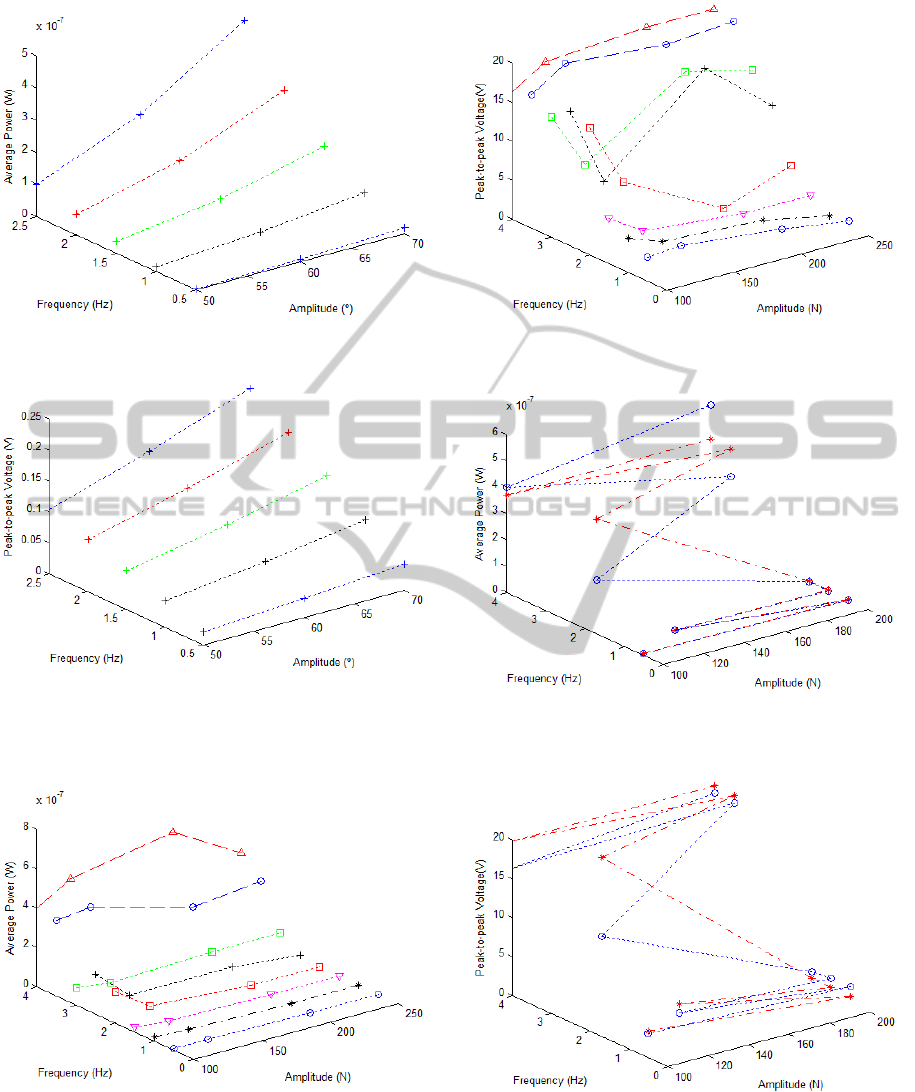
Figure 12: Simulated average power harvested from the
REEH transducer.
Figure 13: Simulated voltage harvested from the REEH
transducer.
9.1 µW for frequencies of 3.5 Hz and 4 Hz.
Figure 14: Experimental average power harvested from the
PEH transducer.
3.4 Discussion
The concept of energy harvesting from multiple
energy sources was proved in this study as a reliable
Figure 15: Experimental voltage harvested from the PEH
transducer.
Figure 16: Validation of the average power harvested from
the PEH transducer (dash-dot line refers to the network
output).
Figure 17: Validation of the voltage harvested from the PEH
transducer (dash-dot line refers to the network output).
methodology to suffice the electrical power needs
of smart hip prosthesis. According to Morais et
al. (2011), a total energy consumption of about
360 µJ with an average power of 1.21 µW is
BIODEVICES 2012 - International Conference on Biomedical Electronics and Devices
78

required to power a telemetric system of a hip
prosthesis for a working period of 300 seconds.
Three transducers provide electric energy to supply a
telemetry system, but they also ensure the availability
of the electric supply, underlining the development
of optimized electric power harvesting elements from
multiple energy sources, towards the design of a
new concept of smart hip prosthesis based on its
lifetime extension. However, experimental results
show that each transducer must be optimized in
order to maximize electric generation during typical
walking speeds, namely in the range between 0.5
Hz and 2 Hz, and to allow the osteointegration
monitoring as well as mechanical micro-stimulation.
Due to the tracking performance of the control
operations of the testing machine, a small loosening
between the acetabular component and the femoral
head occurs when the current force is near to zero
in the tracking of sinusoidal trajectories. This
explains the higher values of the voltage harvested
from the PEH transducer for 100 N of amplitude
over higher amplitudes for the same frequency. The
developed models for the electromagnetic transducers
do not perfectly represent all possible dynamics of
the electric power generation process. More accurate
models are being designed to carry out optimization
programs. The piezoelectric transducer must be
redesigned to remain attached to the hip prosthesis
but its dynamic behaviour should not be significantly
affected by the mechanical properties of the implant.
Also note that the energy profiles must be simulated
and measured under in-vitro and in-vivo realistic
conditions.
Although the power harvested from the TEEH
transducer is dominant over the other transducers, all
the three bio-generators are being optimized in order
to maximize its ability to harvest energy from the
human motion. The development of efficient power
management modules is outside the scope of this
study.
3.4.1 Optimization of the TEEH Generator
The major problem of this transducer is the matching
between the frequency range of the hip kinematics
of patients and the resonant frequency of this
bio-generator. A possible solution to this problem
is the development of a broadband energy harvesting
that must carry out the power maximization over
all the frequency range of the hip joint kinematics.
Another problem of this transducer is the use of a
coil spring, because the spring constant decreases
over time during operation, which can jeopardize the
autonomy of the smart hip prosthesis. Magnetically
levitated generators are a potential solution for this
specific situation, which must however be designed
for a broadband application.
3.4.2 Optimization of the REEH Generator
A constant magnetic field and an average radius
for the coils were assumed in the model presented
in section 2.4.1. However, the magnetic field,
produced by the several magnets put in the acetabular
component, is neither constant nor uniform, which
makes expression 7 for the voltage generation a
highly nonlinear function. On the other hand, the
magnets are at a distance from the winding such that
the magnetic field over the winding is very low.
Several issues must be considered in order to
maximize the generation of electric power by this
transducer: (1) minimize the distance between the
magnets and the winding; (2) maximize the radius of
the winding and the number of wire turns; (3) setup
concave magnets in order to ensure a uniform
magnetic field; (4) setup a core of a material with
very high relative permeability; (5) development of
a transducer design based on a broadband approach.
3.4.3 Optimization of the PEH Generator
The piezoelectric transducer was designed with
only a single piezoelectric element, which resonant
frequency is much higher than the frequency of the
hip joint kinematics. The presented piezoelectric
harvesting is not based on a cantilevered broadband
vibro-impacting power transducer methodology,
which performs high vibration frequencies after
mechanical impacts. Besides, the installation of a
stack of piezoelectric elements with much lower
resonant frequency and performing as a broadband
energy harvesting must be considered in order to
multiply the generation of electric energy.
4 CONCLUSIONS AND FINAL
REMARKS
The development of smart prosthesis is a rising trend
of the concept of instrumented prosthesis. In the
case of the hip prosthesis, expertise methodologies
are claimed to be developed in order to preventively
fix the loosening problem during the lifetime of
the implant in order to avoid revision procedures.
The first demand to achieve this goal is the design
of energy harvesting elements to electrically supply
the telemetric systems and the design of active
mechanisms that can preventively fix the loosening
problem. This paper reports the first study about
MULTI-SOURCE ENERGY HARVESTING POWER GENERATORS FOR INSTRUMENTED IMPLANTS - Towards
the Development of a Smart Hip Prosthesis
79

the development of an energy harvesting system
from multiple sources for smart hip prosthesis.
Considering the energy obtained from the movement
as the most abundant in the human body, three
energy harvesting power bio-generators, namely a
piezoelectric-based and two electromagnetic-based
harvesting elements, were designed to harvest energy
from several movements over the femoral component.
They were able to produce energy to supply the
power needs of a telemetric system. This approach
ensures the availability of the electric power supply
and operates autonomously, safely and without
maintenance during the lifetime of the hip prosthesis.
An ongoing optimization of the harvesting elements
is being conducted in order to improve the electric
power bio-generation up to levels required by the
active actuators that would prevent the aseptic
loosening.
ACKNOWLEDGEMENTS
The present work was conducted with the support of
the FCT - Foundation for Science and Technology,
under the PTDC/EME-PME/105465/2008 project.
REFERENCES
Alpuim, P., Filonovich, S., Costa, C., Rocha, P., Vasilevskiy,
M., Lanceros-Mendez, S., Frias, C., Marques, A.,
Soares, R., and Costa, C. (2008). Fabrication of
a strain sensor for bone implant failure detection
based on piezoresistive doped nanocrystalline silicon.
Journal of Non-Crystalline Solids, 354:2585–2589.
Beeby, S., Tudor, M., and White, N. (2006). Energy
harvesting vibration sources for microsystems
applications. Measurement Science and Technology,
17:R175–R195.
Beeby, S. and White, N. (2010). Energy Harvesting for
Autonomous Systems. Artech House, Norwood, MA,
EUA.
Carmo, J., Ribeiro, J., Silva, M., Goncalves, L., and
Correia, J. (2010). Thermoelectric generator and
solid-state battery for stand-alone microsystems.
Journal of Micromechanics and Microengineering,
20:1–8.
Cook-Chennault, K., Thambi, N., and Sastry, A. (2008).
Powering mems portable devices a review of
non-regenerative and regenerative power supply
systems with special emphasis on piezoelectric energy
harvesting systems. Smart Materials and Structures,
17:1–33.
Damm, P., Graichen, F., Rohlmann, A., Bender, A., and
Bergmann, G. (2010). Total hip joint prosthesis for
in vivo measurement of forces and moments. Medical
Engineering & Physics, 32:95–100.
duToit, N., Wardle, B., and Kim, S. (2005). Design
considerations for mems-scale piezoelectric
mechanical vibration energy harvesters. Integrated
Ferroelectrics, 71:121–160.
Frias, C., Reis, J., e Silva, F. C., Potes, J., Sim˜oes, J., and
Marques, A. (2010). Polymeric piezoelectric actuator
substrate for osteoblast mechanical stimulation.
Journal of Biomechanics, 43:1061–1066.
Gilbert, J. and Balouchi, F. (2008). Comparison of energy
harvesting systems for wireless sensor networks.
International Journal of Automation and Computing,
5(4):334–347.
Graichen, F., Bergmann, G., and Rohlmann, A. (1999).
Hip endoprosthesis for in vivo measurement of joint
force and temperature. Journal of Biomechanics,
32:1113–1117.
Heinlein, B., Graichen, F., Bender, A., Rohlmann, A.,
and Bergmann, G. (2007). Design, calibration and
pre-clinical testing of an instrumented tibial tray.
Journal of Biomechanics, 40:S4–S10.
Heinlein, B., Kutzner, I., Graichen, F., Bender, A.,
Rohlmann, A., Halder, A., Beier, A., and Bergmann,
G. (2009). ESB clinical biomechanics award 2008:
Complete data of total knee replacement loading for
level walking and stair climbing measured in vivo with
a follow-up of 610 months. Clinical Biomechanics,
24:315–326.
Ida, N. (2004). Engineering Electromagnetics. Springer,
New York, 2nd edition.
Kalogirou, S. (2000). Applications of artificial
neural-networks for energy systems. Applied
Energy, 67:17–35.
Ka´zmierski, T. and Beeby, S. (2011). Energy Harvesting
Systems - Principles, Modeling and Applications.
Springer, New York, EUA.
Kerzenmacher, S., Ducr´ee, J., Zengerle, R., and von
Stetten, F. (2008). Energy harvesting by implantable
abiotically catalyzed glucose fuel cells. Journal of
Power Sources, 182:1–17.
Kurtz, S., Ong, K., Lau, E., Mowat, F., and Halpern,
M. (2007). Projections of primary and revision hip
and knee arthroplasty in the united states from 2005
to 2030. The Journal of Bone and Joint Surgery
(American), 89(4):780–785.
Lu, M., Zhang, G., Fu, K., Yu, G., Su, D., and Hu, J. (2011).
Gallium nitride schottky betavoltaic nuclear batteries.
Energy Conversion and Management, 52:1955–1958.
Marcelli, E., Scalambraa, F., Cercenelli, L., and Plicchi,
G. (2007). A new hermetic antenna for wireless
transmission systems of implantable medical devices.
Medical Engineering & Physics, 29:140–147.
Marschner, U., Grtz, H., Jettkant, B., Ruwischa, D.,
Woldt, G., Fischer, W., and Clasbrummel, B. (2009).
Integration of a wireless lock-in measurement of hip
prosthesis vibrations for loosening detection. Sensors
and Actuators A: Physical, 156:145–154.
Morais, R., Frias, C., Silva, N., Azevedo, J., Serˆodio, C.,
Silva, P., Ferreira, J., Sim˜oes, J., and Reis, M. (2009).
An activation circuit for battery-powered biomedical
BIODEVICES 2012 - International Conference on Biomedical Electronics and Devices
80

implantable systems. Sensors and Actuators A:
Physical, 156:229–236.
Morais, R., Silva, N., Santos, P., Frias, C., Ferreira, J.,
Ramos, A., Sim˜oes, J., Baptista, J., and Reis, M.
(2010). Permanent magnet vibration power generator
as an embedded mechanism for smart hip prosthesis.
Procedia Engineering, 5:766–769.
Morais, R., Silva, N., Santos, P., Frias, C., Ferreira,
J., Ramos, A., Sim˜oes, J., Baptista, J., and Reis,
M. (2011). Double permanent magnet vibration
power generator for smart hip prosthesis. Sensors
andActuatorsA: Physical, In Press, Corrected Proof.
Morlock, M., Schneider, E., Bluhm, A., Vollmer, M.,
Bergmann, G., M¨uller, V., and Honl, M. (2001).
Duration and frequency of every day activities in total
hip patients. Journal of Biomechanics, 34:873–881.
Priya, S. and Inman, D. (2009). Energy Harvesting
Technologies. Springer, New York, USA.
Puers, R., Catrysse, M., Vandevoorde, G., Collier, R.,
Louridas, E., Burny, F., Donkerwolcke, M., and
Moulart, F. (2000). A telemetry system for the
detection of hip prosthesis loosening by vibration
analysis. Sensors and Actuators A: Physical,
85:42–47.
Renno, J., Daqaq, M., and Inman, D. (2009). On the optimal
energy harvesting from a vibration source. Journal of
Sound and Vibration, 320:386–405.
Rohlmann, A., Graichen, F., Bender, A., Kayser, R., and
Bergmann, G. (2008). Loads on a telemeterized
vertebral body replacement measured in three patients
within the first postoperative month. Clinical
Biomechanics, 23:147–158.
Rowlands, A., Duck, F., and Cunningham, J. (2008). Bone
vibration measurement using ultrasound: Application
to detection of hip prosthesis loosening. Medical
Engineering & Physics, 30:278–284.
Santos, M., Rolo, D., Ferreira, J., Ramos, A., and Boeri,
C. (2011). Fuzzy control of a servopneumatic wear
simulator of acetabular components of hip prosthesis
- implementing nonlinear controllers for the angular
movement of three coupled. In Proceedings of the 8th
International Conference on Informatics in Control,
Automation and Robotics, pages 155–160.
von B¨uren, T., Mitcheson, P., Green, T., Yeatman, E.,
Holmes, A., and Tr¨oster, G. (2006). Optimization
of inertial micropower generators for human walking
motion. IEEE Sensors Journal, 6(1):28–38.
Wei, X. and Liu, J. (2008). Power sources and electrical
recharging strategies for implantable medical devices.
Frontiers of Energy and Power Engineering in China,
2(1):1–13.
Westerhoff, P., Graichen, F., Bender, A., Rohlmann, A.,
and Bergmann, G. (2009). An instrumented implant
for in vivo measurement of contact forces and contact
moments in the shoulder joint. Medical Engineering
& Physics, 31:207–213.
Whittle, M. (2007). Gait analysis - An introduction.
Butterworth Heinemann Elsevier, 4th edition.
Winter, D. (2009). Biomechanics and motor control of
human movement. John Wiley & Sons, 4th edition.
Zhu, D., Tudor, M., and Beeby, S. (2010). Strategies for
increasing the operating frequency range of vibration
energy harvesters: a review. Measurement Science
and Technology, 21:1–29.
MULTI-SOURCE ENERGY HARVESTING POWER GENERATORS FOR INSTRUMENTED IMPLANTS - Towards
the Development of a Smart Hip Prosthesis
81
