
ENERGY EFFICIENCY EVALUATION OF VOLTAGE
CONTROL AND FREQUENCY CONTROL OVER AN
INDUCTIVE POWER LINK FOR BIOMEDICAL IMPLANTS
Pablo Aqueveque, Marcial Saez and Rodrigo Rosales
Electrical Engineering Department, University of Concepcion, Concepcion, Chile
Keywords: Efficiency, Implanted Devices, Inductive power Link, Wireless Power Transmission.
Abstract: This article presents the analysis of the efficiency of two control systems used to regulate the DC voltage in
an implanted device fed by an inductive power link. Both control systems work outside the body,
eliminating the voltage regulator in the implanted circuit (inside the body). These ways of voltage control
reduce the power and heat dissipated inside the body. The first control system involves regulation of power
supply voltage to the high frequency amplifier. The second control system adjusts the frequency of the
inductive link. A laboratory prototype was built and experimental results were obtained. It is shown that for
a range of distance between 0 mm and 11.8 mm the efficiency of the system is greater when using
amplitude voltage control. Above that distance, the efficiency of frequency control is better. A difference of
20% was obtained in the optimal points.
1 INTRODUCTION
Over the past few decades, the inductive powering
link has been studied and used for transmitting
energy wirelessly to Implantable Microelectronic
Devices (IMDs), such as cochlear prosthesis, visual
prosthesis, cortical neuromotor prosthesis and
implantable sensors, to name just a few. This kind of
transmission energy avoids wires crossing the skin,
which have a high risk of infection or other
problems for the patient. It is also used to avoid
placing rechargeable batteries inside the body,
because they have a limited lifetime and will require
new surgery to replace them (Ma et. al., 2010).
A basic remote powering link scheme has four
main parts: A high frequency power amplifier, an
inductive link, a high frequency rectifier, and a
voltage regulator. MOSFET based Class D and
Class E amplifiers are the most used high frequency
power amplifiers because of their higher efficiency
at high frequencies (Atluri and Ghovanloo, 2006). In
the inductive link, the common resonance topology
is a series L-C tuned primary circuit and parallel L-C
tuned secondary circuit due to its high voltage gain
and efficiency characteristics (over 80%) at low
coupling ranges (Ali, Ahmad and Khan, 2009). The
distance between coils varies the mutual inductance
between primary and secondary coils, and hence, the
coupling coefficient (k); therefore, the choice of
shape, number of turns, diameter and size of the
primary and secondary coils allows a good position
tolerance. The high frequency rectifier is normally
half or full bridge with very fast switching Schottky
diodes (Dissanayake et. al., 2009).
External batteries are used to feed the wireless
power transmission for implanted devices. These
applications need to have a small size and light
weight external control box for patient mobility and
comfort. Battery lifetime must be maximized in
order to give the patient more autonomy without the
need of frequent changing the external battery.
Most of the implantable electronic devices need
a constant supply voltage to work properly, which
means that the voltage on the secondary coil has to
be regulated for some kind of control system that
produces a constant voltage. There are two main
approaches: Magnitude voltage control and
frequency control. The first one varies the
magnitude of the power supply voltage that feeds the
high frequency amplifier, in order to vary the power
delivered to the inductive link (and consequently to
the load) (Si et. al., 2007). And the second one
varies the frequency of the voltage that feeds the
inductive link, moving the frequency value around
the resonant situation (Si et. al., 2008).
359
Aqueveque P., Saez M. and Rosales R..
ENERGY EFFICIENCY EVALUATION OF VOLTAGE CONTROL AND FREQUENCY CONTROL OVER AN INDUCTIVE POWER LINK FOR
BIOMEDICAL IMPLANTS.
DOI: 10.5220/0003792403590363
In Proceedings of the International Conference on Biomedical Electronics and Devices (BIODEVICES-2012), pages 359-363
ISBN: 978-989-8425-91-1
Copyright
c
2012 SCITEPRESS (Science and Technology Publications, Lda.)
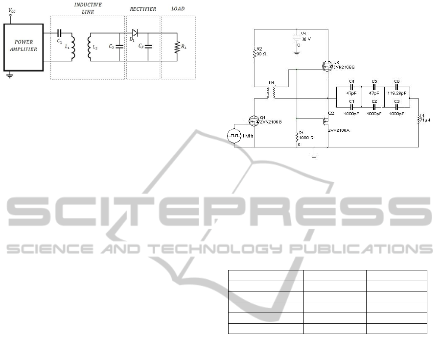
Figure 1: Four main parts of the circuit of the system.
Both control systems have the goal of maintaining a
constant voltage at the load, improving the overall
reliability of the system.
This paper analyzes the inductive link efficiency
of both control systems when the distance between
the primary and secondary coils is changed.
2 INDUCTIVE POWERING LINK
When analyzing the inductive powering link it is
necessary to consider several parts.
2.1 System
The system used in this study consists in four main
parts (showed in figure 1): High Frequency power
amplifier, inductive link, high frequency rectifier,
and load. A detailed description of each part is
presented below.
2.1.1 Power Amplifier
There are several classes of power amplifiers (A,
AB, B, C, D and E) that can be used. Class D and
class E power amplifiers are the most used for
inductive links, because of their high efficiency,
over 80%. In this paper, a Class D Power Amplifier
based on push-pull Mosfet’s configuration is used.
The amplifier works at 1MHz and is fed by a
variable 30V power supply. The schematic circuit is
shown in figure 2.
2.1.2 Inductive Link
The inductive link is composed of the external
primary coil and the implanted secondary coil. There
are different options of circuit configurations, where
the resonance topology is the most effective option,
because it makes the final circuit band limited,
improving the voltage gain and link efficiency.
Studies proposed that the series-tuned primary and
parallel-tuned secondary circuit is the ideal
configuration because of its good displacement
tolerance, high voltage gain and efficiency
characteristics at low coupling ranges (Ali, Ahmad
and Khan, 2009).
Figure 2: Power amplifier, driver and series tuned primary
coil.
We decided to work with circular coils. The
parameters of the resultant inductive link are listed
in table 2.
Table 1: Parameters of the series tuned primary and
parallel tuned secondary coils.
Parameters Primary Secondary
Number of turns 30 20
Coil Diameter 50 mm 50 mm
Wire Diameter 0.28 mm 0.28mm
Inductance 71 μH 42 μH
Resistance 1.1 Ω 0.7 Ω
2.1.3 Rectifier
A simple half-wave rectifier is used to rectify the
AC signal generated on the implanted tuned coil.
This topology is appropriate to this application
because it has less consumption than a full-wave
rectifier (because it has only one diode). The
rectifier is composed of a 1N5819 Schottky diode.
The high frequency of the inductive link (1MHz)
reduces the size of the parallel capacitor used as a
filter, in order to have a continuous voltage with an
acceptable ripple (less than 10%).
2.2 Model of Inductive Link
We need to consider model of the inductive link, in
order to gain more knowledge about the coupling
coefficient, critical coupling, voltage transfer ratio,
and efficiency of the link.
BIODEVICES 2012 - International Conference on Biomedical Electronics and Devices
360

2.2.1 Coupling coefficient and Critical
Voltage Transfer Ratio
The coupling coefficient of the system is defined by
(1).
=
∙
(1)
Where k is the coupling coefficient of the
inductive link, M is the mutual inductance between
the two coils, L
1
is the self-inductance of the
external coil (primary), and L
2
is the self-inductance
of the implanted coil (secondary).
The inductive link frequency was selected
considering the limitation on power density within
the body (<80mW/cm
2
) (Zumsteg, 2004) in order to
avoid tissue damage. In this case the frequency used
was 1MHz. In resonance condition, the resonant
frequency (ω
0
) of the system is defined by (2)
=
1
∙
=
1
∙
(2)
2.2.2 Definition of Overall Efficiency
The model presented in (Donaldson and Perkins,
1983) shows that the transmitter has a resistance R
1
,
and the receiver has a resistance R
2
, which means
that in every stage there are power losses, which
change the overall efficiency (η
o
) of the system. This
efficiency can be expressed by (3).
=
+
+
+
+
+
+
(3)
Composed of the power consumption off the
oscillator (P
A
), dissipation in ouput stage not
accounted by the oscillator (P
B
), and the power
consumption dissipated in circuits; on the transmitter
side: by the power in the resistance of the power
supply voltage (P
C
), power in the resistance of the
primary coil (P
D
), and in the receiver side, by the
power in the resistance of the secondary coil (P
E
),
the power in the rectifier (P
F
), and the useful power
(P
G
).
3 CONTROL METHODS FOR A
REGULATED VOLTAGE
The control of the load voltage is important to obtain
a steady output voltage during coupling variations
between the primary and the secondary coil, which
could be used as the power supply to some
implanted circuit. This can be done by two main
methods: Amplitude voltage control and frequency
control. The amplitude voltage control and
frequency control can be produced in several ways.
One of the proposed options is controlling from the
external system (Silay, Dehollain and Declercq,
2010), and the other one is controlling from the
internal circuit (Donaldson, 1985). For simplicity,
we used the first one in this paper.
Figure 3: Inductive link prototype for measurements.
4 OVERALL EFFICIENCY OF
THE SYSTEM AND
EXPERIMENTAL RESULTS
The overall efficiency of the system was empirically
established by using two control methods.
Amplitude voltage control and frequency control, for
a fixed voltage at the load of 5V. The position of the
primary coil was fixed, and the distance of the
secondary coil was incremented by 2 mm for every
measurement, in order to see the difference of
efficiency produced by the change of the distance
between the coils. The circuit and instruments used
are shown in figure 3. All the measures were done
with a 100MHz digital oscilloscope and computed in
Matlab.
4.1 Measurements with Amplitude
Voltage Control
The voltage controller varied the supply voltage of
the primary circuit to maintain a constant load
voltage at the secondary circuit for each distance,
with a constant frequency of the system of 1 MHz.
The measurements started 0 mm between the coils,
and were increased until 25 mm, with measurements
every 2 mm. The input voltage shows an exponential
behavior from 5V to 32V with respect to the
distance, which means that it is not possible to reach
a greater distance between the coils, because it
would supply an input voltage greater than the
maximum voltage permitted by electronic
components.
ENERGY EFFICIENCY EVALUATION OF VOLTAGE CONTROL AND FREQUENCY CONTROL OVER AN
INDUCTIVE POWER LINK FOR BIOMEDICAL IMPLANTS
361

4.2 Measurements with Frequency
Control
The frequency controller varied the frequency of the
system from 1.28 MHz to 1.05 MHz in order to
maintain a constant load voltage at the secondary
circuit for each distance, with a constant supply
voltage of 7 V. The measurements started at 0 mm
between the coils, and were increased until 35 mm,
with measurements every 2 mm.
Figure 4: Efficiency of the amplitude voltage control and
frequency control at each distance.
It was not possible to maintain a constant output
voltage with a value of 5V for a distance between
the coils was greater than 35 mm.
4.3 Efficiency of Both Control Systems
The overall efficiency of both control systems was
measured in order to compare the two ways of
maintaining a constant output voltage at a certain
value. Figure 4 shows that the efficiency of the
amplitude voltage control is greater at distances
between 0 mm and 11.8 mm, and over that distance,
the efficiency of the frequency control is greater.
The amplitude voltage control has a greater
maximum voltage, but is more sensitive to distance
changes. On the other hand, the frequency control
has fewer variations of efficiency at different
distances, but its maximum efficiency value is less
than the maximum efficiency of the amplitude
voltage value.
5 CONCLUSIONS
An analysis of the efficiency of two control systems
used to regulate the DC voltage in an implanted
device fed by an inductive power link was presented.
Both control systems work outside the body,
eliminating the voltage regulator in the implanted
circuit (inside the body). These ways of voltage
control reduce the power and heat dissipated inside
the body. The first control system regulates the
power supply voltage and the second adjusts the
frequency of the inductive link. Experimental results
show that the efficiency of the system is greater
when using amplitude voltage control for a range of
distance between 0 mm and 11.8 mm. Above that,
frequency control is better. A difference of 20% was
obtained at the optimal points.
ACKNOWLEDGEMENTS
This paper was developed with support of
postdoctoral project 3100136 of the Chilean Fund
for Science and Technology Development
(FONDECYT).
REFERENCES
Ali, H., Ahmad, T. J., Khan, S. A., “Mathematical
Modeling of an Inductive Link for Optimizing
Efficiency”, IEEE Symposium on Industrial
Electronics an Applications (ISIEA), pp. 831-835,
October 2009.
Atluri, S., and Ghovanloo, M., “Incorporating Back
Telemetry in a Full-Wave CMOS Rectifier for RFID
and Biomedical Applications”, IEEE International
Symposium on Circuits and Systems (ISCAS), June
2007.
Dissanayake, T. D., Hu, A. P., Malpas, S., Bennet, L.,
Taberner, A., Booth, L., and Budgett, D.,
“Experimental Study of a TET System for Implantable
Biomedical Devices”. IEEE Transactions on
Biomedical Circuits and Systems, vol. 3, no. 6, Dec.
2009.
Donaldson, N. N., and Perkins, T. A., “Analysis of
resonant coupled coils in the design of radio frequency
transcutaneous links”. Med. & Biol. Eng. & Comput.,
21, 612-627, Sept. 1983
Donaldson N. N., “Use of feedback with voltage
regulators for implants powered by coupled coils”.
Med. & Biol. Eng. & Comput., 23, 291, 1985.
Ma, Q., Haider, M. R., Yuan, S., Islam, S. K., “Power-
Oscillator Based High Efficiency Inductive Power-
Link for Transcutaneous Power Transmission”. 53rd
IEEE International Midwest Symposium on Circuits
and Systems (MWSCAS), pp. 537-540, Aug. 2010.
Si, P., Hu, A. P., Hsu, J. W., Chiang, M., Wang, Y.,
Malpas, S., and Budgett, D., “Wireless Power Supply
for Implantable Biomedical Device Based on Primary
Input Voltage Regulation”. 2nd IEEE Conf. Industrial
BIODEVICES 2012 - International Conference on Biomedical Electronics and Devices
362

Electronics and Applications (ICIEA), pp. 235-239,
2007.
Si, P., Hu, A. P., Malpas, S., Budgett, D., “A Frequency
Control Method for Regulating Wireless Power to
Implantable Devices”. IEEE Transactions on
Biomedical Circuits and Systems, vol. 2, no. 1, pp. 22-
29, March, 2008.
Silay, K. M., Dehollain, C., Declercq, M., “Inductive
Power Link for a Wireless Cortical Implant with
Biocompatible Packaging”, IEEE Sensors, pp. 94-98,
Nov. 2010.
Zumsteg, Z. S. "Power Feasibility of Implantable Digital
Spike-Sorting Circuits for Neural Prosthetic Systems,"
Proceedings of the 26
th
Annual International
Conference of the IEEE EMBS, pp. 4237-240, 2004.
ENERGY EFFICIENCY EVALUATION OF VOLTAGE CONTROL AND FREQUENCY CONTROL OVER AN
INDUCTIVE POWER LINK FOR BIOMEDICAL IMPLANTS
363
